2002 DODGE RAM lock
[x] Cancel search: lockPage 169 of 2255
(8) Select a shim equal to the dial indicator read-
ing plus the drive pinion gear depth variance number
etched in the face of the pinion gear (Fig. 4) using
the opposite sign on the variance number. For exam-
ple, if the depth variance is ±2, add +0.002 in. to the
dial indicator reading.
(9) Remove the pinion depth gauge components
from the axle housing
DIFFERENTIAL BEARING PRELOAD AND GEAR
BACKLASH
Differential side bearing preload and gear backlash
is achieved by selective shims positioned behind thedifferential side bearing cones. The proper shim
thickness can be determined using slip-fit dummy
bearings D-346 in place of the differential side bear-
ings and a dial indicator C-3339. Before proceeding
with the differential bearing preload and gear back-
lash measurements, measure the pinion gear depth
and prepare the pinion gear for installation. Estab-
lishing proper pinion gear depth is essential to estab-
lishing gear backlash and tooth contact patterns.
After the overall shim thickness to take up differen-
tial side play is measured, the pinion gear is
installed, and the gear backlash shim thickness is
measured. The overall shim thickness is the total of
the dial indicator reading and the preload specifica-
tion added together. The gear backlash measurement
determines the thickness of the shim used on the
ring gear side of the differential case. Subtract the
gear backlash shim thickness from the total overall
shim thickness and select that amount for the pinion
gear side of the differential (Fig. 10). Differential
shim measurements are performed with axle
spreader W-129-B removed.
SHIM SELECTION
NOTE: It is difficult to salvage the differential side
bearings during the removal procedure. Install
replacement bearings if necessary.
(1) Remove differential side bearings from differ-
ential case.
(2) Remove factory installed shims from differen-
tial case.
(3) Install ring gear on differential case and
tighten bolts to specification, if necessary.
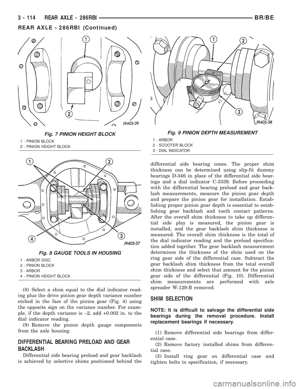
Fig. 7 PINION HEIGHT BLOCK
1 - PINION BLOCK
2 - PINION HEIGHT BLOCK
Fig. 8 GAUGE TOOLS IN HOUSING
1 - ARBOR DISC
2 - PINION BLOCK
3 - ARBOR
4 - PINION HEIGHT BLOCK
Fig. 9 PINION DEPTH MEASUREMENT
1 - ARBOR
2 - SCOOTER BLOCK
3 - DIAL INDICATOR
3 - 114 REAR AXLE - 286RBIBR/BE
REAR AXLE - 286RBI (Continued)
Page 175 of 2255
SPECIFICATIONS
REAR AXLE - 286RBI
AXLE SPECIFICATIONS
DESCRIPTION SPECIFICATION
Axle Ratio 3.55, 4.10
Ring Gear Diameter 286 mm (11.25 in.)
Ring Gear Backlash 0.12-0.20 mm (0.005-0.008 in.)
Pinion Gear Standard Depth 147.625 mm (5.812 in.)
Pinion Bearing Preload - Original Bearings 1-2 N´m (10-20 in. lbs.)
Pinion Bearing Preload - New Bearings 2.8-5.1 N´m (25-45 in. lbs.)
TORQUE SPECIFICATIONS
DESCRIPTION N´m Ft. Lbs. In. Lbs.
Fill Hole Plug 34 25 -
Differential Cover Bolts 47 35 -
Bearing Cap Bolts 108 80 -
Ring Gear Bolt 298 220 -
Pinion Nut 637-678 470-500 -
Axle Shaft Bolts 128 95 -
Trac-LocTCase Bolts 122-136 90-100 -
* Hub Bearing Nut 163-190 120-140 -
* Torque to spec. then back off nut 1/8 to 1/3 turn and install locking wedge.
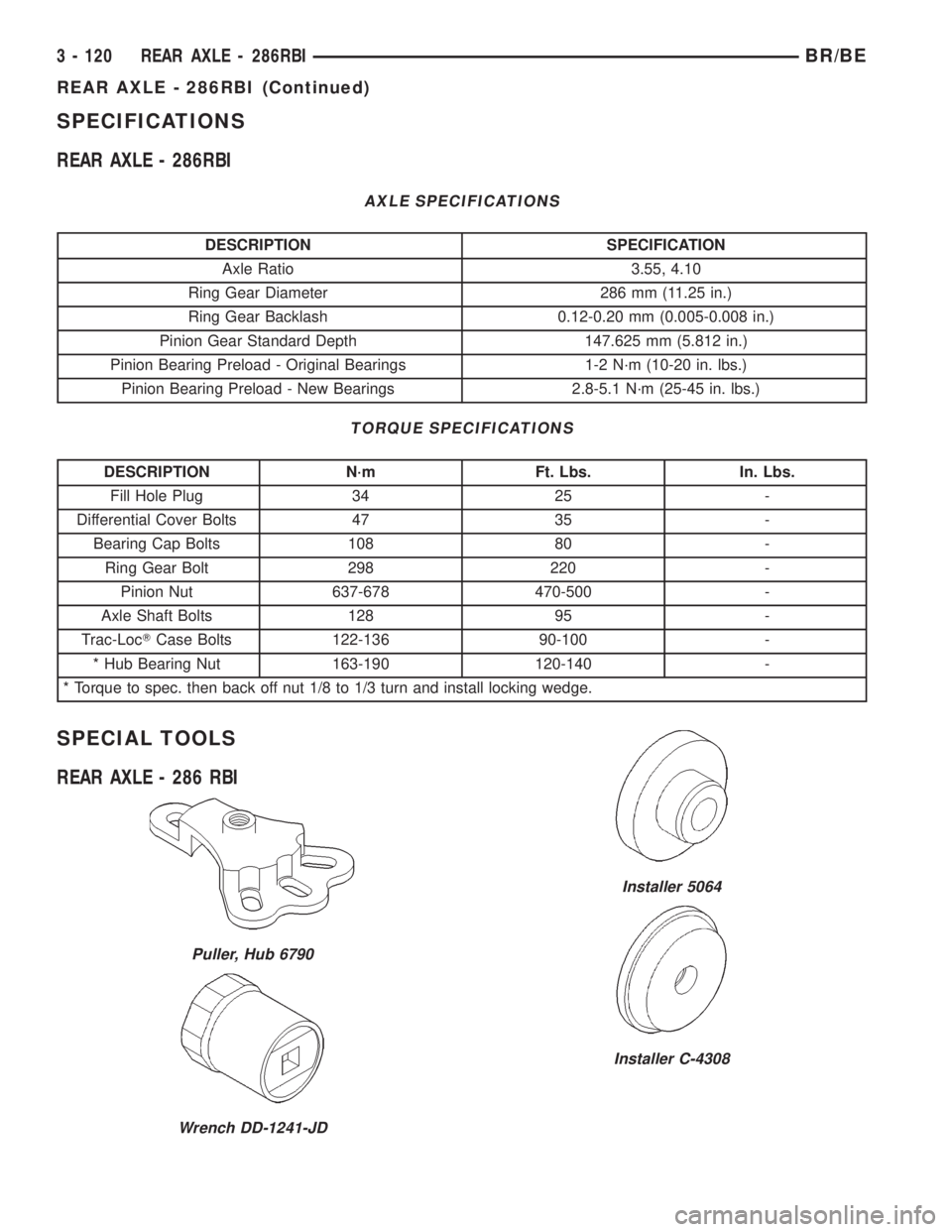
SPECIAL TOOLS
REAR AXLE - 286 RBI
Puller, Hub 6790
Wrench DD-1241-JD
Installer 5064
Installer C-4308
3 - 120 REAR AXLE - 286RBIBR/BE
REAR AXLE - 286RBI (Continued)
Page 178 of 2255
AXLE SHAFTS
REMOVAL
(1) Remove the axle shaft flange bolts.
(2) Slide the axle shaft out from the axle tube.
INSTALLATION
(1) Clean the gasket contact surface area on the
flange with an appropriate solvent. Install a new
flange gasket and slide the axle shaft into the tube.
(2) Install the bolts and tighten to 129 N´m (95 ft.
lbs.).
AXLE BEARINGS
REMOVAL
(1) Remove wheel and tire assembly.
(2) Remove brake drum.
(3) Remove the axle shaft.
(4) Remove the lock wedge and adjustment nut.
Remove adjustment nut with Socket DD-1241-JD.
(5) Remove the hub assembly. The outer axle bear-
ing will slide out as the hub is being removed.
(6) Drive grease seal and inner bearing out of the
hub with Installer 5064 and Handle C-4171.
(7) Remove bearing cups from the hub with a
brass drift and a hammer.
INSTALLATION
(1) Thoroughly clean both axle bearings and inte-
rior of the hub with an appropriate cleaning solvent.
(2) Install bearing cups with Installer 8153 and
Handle C-4171.
(3) Pack inner and outer bearings with Mopar
wheel bearing grease or equivalent
(4) Apply lubricant to surface area of the bearing
cup.
(5) Install inner axle bearing in the hub.
(6) Install anewbearing grease seal with
Installer 8152 and Handle C-4171.
(7) Inspect bearing and seal contact surfaces on
the axle tube spindle for burrs and/or roughness.
Remove all the rough contact surfaces from the axle
spindle.
CAUTION: Do not let grease seal contact the axle
tube threads during installation.
(8) Carefully slide the hub onto the axle.
(9) Install outer axle bearing.
(10) Install hub bearing adjustment nut with
Socket DD-1241±JD.
(11) Tighten adjustment nut to 163-190 N´m (120-
140 ft. lbs.) while rotating the wheel.(12) Loosen adjustment nut 1/8 of-a-turn to pro-
vide 0.001-inch to 0.010-inch wheel bearing end play.
(13) Tap the locking wedge into the spindle key-
way and adjustment nut.
NOTE: Locate locking wedge in a new position in
the adjustment nut.
(14) Install axle shaft and brake drum.
(15) Install wheel and tire assembly.
PINION SEAL
REMOVAL
(1) Raise and support the vehicle.
(2) Mark the universal joint, pinion yoke, and pin-
ion shaft for installation reference.
(3) Disconnect the propeller shaft from the pinion
yoke. Secure the propeller shaft in an upright posi-
tion to prevent damage to the rear universal joint.
(4) Remove wheel and tire assemblies.
(5) Remove brake calipers to prevent any drag.
The drag may cause a false bearing preload torque
measurement.
(6) Rotate pinion yoke three or four times.
(7) Record the amount of torque necessary to
rotate the pinion gear with an inch pound dial-type
torque wrench.
(8) Hold the yoke with Holder 6719A and remove
the pinion shaft nut and washer.
(9) Remove yoke from the pinion with Remover
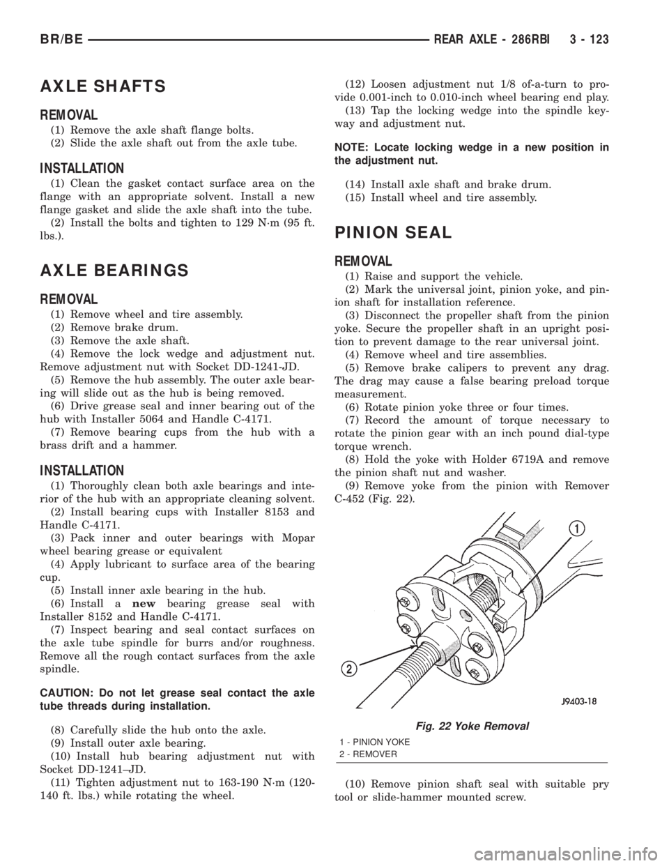
C-452 (Fig. 22).
(10) Remove pinion shaft seal with suitable pry
tool or slide-hammer mounted screw.
Fig. 22 Yoke Removal
1 - PINION YOKE
2 - REMOVER
BR/BEREAR AXLE - 286RBI 3 - 123
Page 181 of 2255
(14) Remove the case from housing. Tag bearing
cups to indicate their location.
DISASSEMBLY
(1) Remove roll-pin holding mate shaft in housing.
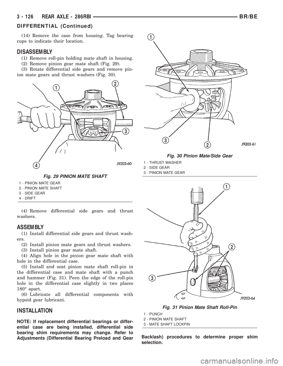
(2) Remove pinion gear mate shaft (Fig. 29).
(3) Rotate differential side gears and remove pin-
ion mate gears and thrust washers (Fig. 30).
(4) Remove differential side gears and thrust
washers.
ASSEMBLY
(1) Install differential side gears and thrust wash-
ers.
(2) Install pinion mate gears and thrust washers.
(3) Install pinion gear mate shaft.
(4) Align hole in the pinion gear mate shaft with
hole in the differential case.
(5) Install and seat pinion mate shaft roll-pin in
the differential case and mate shaft with a punch
and hammer (Fig. 31). Peen the edge of the roll-pin
hole in the differential case slightly in two places
180É apart.
(6) Lubricate all differential components with
hypoid gear lubricant.
INSTALLATION
NOTE: If replacement differential bearings or differ-
ential case are being installed, differential side
bearing shim requirements may change. Refer to
Adjustments (Differential Bearing Preload and GearBacklash) procedures to determine proper shim
selection.
Fig. 29 PINION MATE SHAFT
1 - PINION MATE GEAR
2 - PINION MATE SHAFT
3 - SIDE GEAR
4 - DRIFT
Fig. 30 Pinion Mate/Side Gear
1 - THRUST WASHER
2 - SIDE GEAR
3 - PINION MATE GEAR
Fig. 31 Pinion Mate Shaft Roll-Pin
1 - PUNCH
2 - PINION MATE SHAFT
3 - MATE SHAFT LOCKPIN
3 - 126 REAR AXLE - 286RBIBR/BE
DIFFERENTIAL (Continued)
Page 183 of 2255
(12) Fill the differential with Mopar Hypoid Gear
Lubricant or equivalent to bottom of the fill plug
hole.
(13) Install fill hole plug and tighten to 34 N´m (25
ft. lbs.).
(14) Remove support and lower vehicle.
DIFFERENTIAL - TRAC-LOK
DIAGNOSIS AND TESTING - TRAC-LOKT
The most common problem is a chatter noise when
turning corners. Before removing a Trac-lokŸ unit
for repair, drain, flush and refill the axle with the
specified lubricant. A container of Mopar Trac-lokŸ
Lubricant (friction modifier) should be added after
repair service or during a lubricant change.
After changing the lubricant, drive the vehicle and
make 10 to 12 slow, figure-eight turns. This maneu-
ver will pump lubricant through the clutches. This
will correct the condition in most instances. If the
chatter persists, clutch damage could have occurred.
DIFFERENTIAL TEST
The differential can be tested without removing the
differential case by measuring rotating torque. Make
sure brakes are not dragging during this measure-
ment.
(1) Place blocks in front and rear of both front
wheels.
(2) Raise one rear wheel until it is completely off
the ground.
(3) Engine off, transmission in neutral, and park-
ing brake off.
(4) Remove wheel and bolt Special Tool 6790 or
equivalent tool to studs.
(5) Use torque wrench on special tool to rotate
wheel and read rotating torque.
(6) If rotating torque is less than 22 N´m (30 ft.
lbs.) or more than 271 N´m (200 ft. lbs.) on either
wheel the unit should be serviced.
DISASSEMBLY
The Trac-Loktdifferential on this axle has a one-
piece cross shaft and uses one dished disc, regular 5
disc and 7 plates.
NOTE: Pay attention to the clutch pack arrangement
during disassembly. Note the direction of the con-
cave and convex side of the plates and discs.
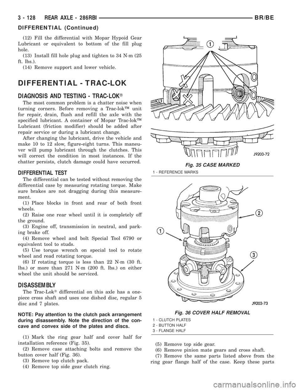
(1) Mark the ring gear half and cover half for
installation reference (Fig. 35).
(2) Remove case attaching bolts and remove the
button cover half (Fig. 36).
(3) Remove top clutch pack.
(4) Remove top side gear clutch ring.(5) Remove top side gear.
(6) Remove pinion mate gears and cross shaft.
(7) Remove the same parts listed above from the
ring gear flange half of the case. Keep these parts
Fig. 35 CASE MARKED
1 - REFERENCE MARKS
Fig. 36 COVER HALF REMOVAL
1 - CLUTCH PLATES
2 - BUTTON HALF
3 - FLANGE HALF
3 - 128 REAR AXLE - 286RBIBR/BE
DIFFERENTIAL (Continued)
Page 187 of 2255
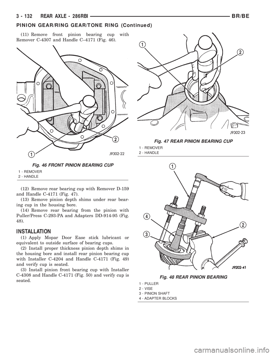
(11) Remove front pinion bearing cup with
Remover C-4307 and Handle C±4171 (Fig. 46).
(12) Remove rear bearing cup with Remover D-159
and Handle C-4171 (Fig. 47).
(13) Remove pinion depth shims under rear bear-
ing cup in the housing bore.
(14) Remove rear bearing from the pinion with
Puller/Press C-293-PA and Adapters DD-914-95 (Fig.
48).
INSTALLATION
(1) Apply Mopar Door Ease stick lubricant or
equivalent to outside surface of bearing cups.
(2) Install proper thickness pinion depth shims in
the housing bore and install rear pinion bearing cup
with Installer C-4204 and Handle C-4171 (Fig. 49)
and verify cup is seated.
(3) Install pinion front bearing cup with Installer
C-4308 and Handle C-4171 (Fig. 50) and verify cup is
seated.
Fig. 46 FRONT PINION BEARING CUP
1 - REMOVER
2 - HANDLE
Fig. 47 REAR PINION BEARING CUP
1 - REMOVER
2 - HANDLE
Fig. 48 REAR PINION BEARING
1 - PULLER
2 - VISE
3 - PINION SHAFT
4 - ADAPTER BLOCKS
3 - 132 REAR AXLE - 286RBIBR/BE
PINION GEAR/RING GEAR/TONE RING (Continued)
Page 193 of 2255
SPECIAL TOOLS
BASE BRAKESHYDRAULIC/MECHANICAL
DESCRIPTION
This vehicle is equipped with front disc brakes and
rear drum brakes also certain vehicles have four
wheel disc brakes. The front and rear disc brakes
consist of dual piston calipers and ventilated rotors.
The rear brakes are dual brake shoe, internal
expanding units with cast brake drums. The parking
brake mechanism is cable operated and connected to
the rear brake trailing shoes. Power brake assist is
standard equipment. A vacuum operated power brake
booster is used on gas engine vehicles. A hydraulic
booster is used on diesel engine vehicles.
Two antilock brake systems are used on this vehi-
cle. A rear wheel antilock (RWAL) brake system and
all-wheel antilock brake system (ABS). The RWAL
and ABS systems are designed to retard wheel
lockup while braking. Retarding wheel lockup is
accomplished by modulating fluid pressure to the
wheel brake units. Both systems are monitored by a
microprocessor which controls the operation of the
systems.
WARNING
WARNING: DUST AND DIRT ACCUMULATING ON
BRAKE PARTS DURING NORMAL USE MAY CON-
TAIN ASBESTOS FIBERS FROM PRODUCTION OR
AFTERMARKET LININGS. BREATHING EXCESSIVE
CONCENTRATIONS OF ASBESTOS FIBERS CAN
CAUSE SERIOUS BODILY HARM. EXERCISE CARE
WHEN SERVICING BRAKE PARTS. DO NOT CLEAN
BRAKE PARTS WITH COMPRESSED AIR OR BY
DRY BRUSHING. USE A VACUUM CLEANER SPE-
CIFICALLY DESIGNED FOR THE REMOVAL OF
ASBESTOS FIBERS FROM BRAKE COMPONENTS.
IF A SUITABLE VACUUM CLEANER IS NOT AVAIL-
ABLE, CLEANING SHOULD BE DONE WITH A
WATER DAMPENED CLOTH. DO NOT SAND, OR
GRIND BRAKE LINING UNLESS EQUIPMENT USED
IS DESIGNED TO CONTAIN THE DUST RESIDUE.
DISPOSE OF ALL RESIDUE CONTAINING ASBES-
TOS FIBERS IN SEALED BAGS OR CONTAINERS
TO MINIMIZE EXPOSURE TO YOURSELF AND OTH-
ERS. FOLLOW PRACTICES PRESCRIBED BY THE
OCCUPATIONAL SAFETY AND HEALTH ADMINIS-
TRATION AND THE ENVIRONMENTAL PROTECTION
AGENCY FOR THE HANDLING, PROCESSING, AND
DISPOSITION OF DUST OR DEBRIS THAT MAY
CONTAIN ASBESTOS FIBERS.
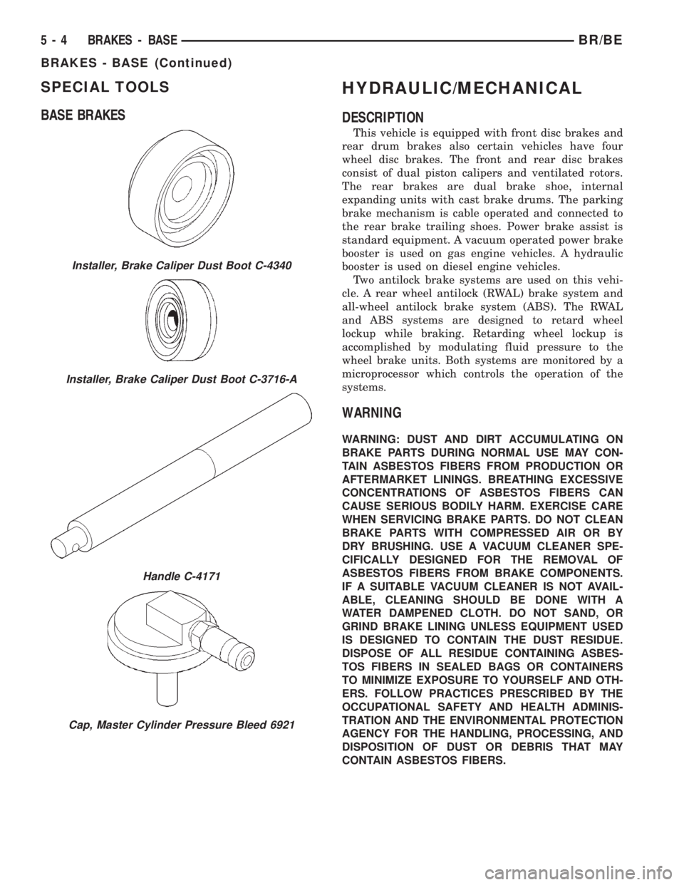
Installer, Brake Caliper Dust Boot C-4340
Installer, Brake Caliper Dust Boot C-3716-A
Handle C-4171
Cap, Master Cylinder Pressure Bleed 6921
5 - 4 BRAKES - BASEBR/BE
BRAKES - BASE (Continued)
Page 194 of 2255

CAUTION: Never use gasoline, kerosene, alcohol,
motor oil, transmission fluid, or any fluid containing
mineral oil to clean the system components. These
fluids damage rubber cups and seals. Use only
fresh brake fluid or Mopar brake cleaner to clean or
flush brake system components. These are the only
cleaning materials recommended. If system contam-
ination is suspected, check the fluid for dirt, discol-
oration, or separation into distinct layers. Also
check the reservoir cap seal for distortion. Drain
and flush the system with new brake fluid if con-
tamination is suspected.
CAUTION: Use Mopar brake fluid, or an equivalent
quality fluid meeting SAE/DOT standards J1703 and
DOT 3. Brake fluid must be clean and free of con-
taminants. Use fresh fluid from sealed containers
only to ensure proper antilock component opera-
tion.
CAUTION: Use Mopar multi-mileage or high temper-
ature grease to lubricate caliper slide surfaces,
drum brake pivot pins, and shoe contact points on
the backing plates. Use multi-mileage grease or GE
661 or Dow 111 silicone grease on caliper slide pins
to ensure proper operation.
DIAGNOSIS AND TESTING - BASE BRAKE
SYSTEM
Base brake components consist of the brake shoes,
calipers, wheel cylinders, brake drums, rotors, brake
lines, master cylinder, booster, and parking brake
components.
Brake diagnosis involves determining if the prob-
lem is related to a mechanical, hydraulic, or vacuum
operated component.
The first diagnosis step is the preliminary check.
PRELIMINARY BRAKE CHECK
(1) Check condition of tires and wheels. Damaged
wheels and worn, damaged, or underinflated tires
can cause pull, shudder, vibration, and a condition
similar to grab.
(2) If complaint was based on noise when braking,
check suspension components. Jounce front and rear
of vehicle and listen for noise that might be caused
by loose, worn or damaged suspension or steering
components.
(3) Inspect brake fluid level and condition. Note
that the brake reservoir fluid level will decrease in
proportion to normal lining wear.Also note that
brake fluid tends to darken over time. This is
normal and should not be mistaken for contam-
ination.(a) If fluid level is abnormally low, look for evi-
dence of leaks at calipers, wheel cylinders, brake
lines, and master cylinder.
(b) If fluid appears contaminated, drain out a
sample to examine. System will have to be flushed
if fluid is separated into layers, or contains a sub-
stance other than brake fluid. The system seals
and cups will also have to be replaced after flush-
ing. Use clean brake fluid to flush the system.
(4) Check parking brake operation. Verify free
movement and full release of cables and pedal. Also
note if vehicle was being operated with parking
brake partially applied.
(5) Check brake pedal operation. Verify that pedal
does not bind and has adequate free play. If pedal
lacks free play, check pedal and power booster for
being loose or for bind condition. Do not road test
until condition is corrected.
(6) Check booster vacuum check valve and hose.
(7) If components checked appear OK, road test
the vehicle.
ROAD TESTING
(1) If complaint involved low brake pedal, pump
pedal and note if it comes back up to normal height.
(2) Check brake pedal response with transmission
in Neutral and engine running. Pedal should remain
firm under constant foot pressure.
(3) During road test, make normal and firm brake
stops in 25-40 mph range. Note faulty brake opera-
tion such as low pedal, hard pedal, fade, pedal pulsa-
tion, pull, grab, drag, noise, etc.
(4) Attempt to stop the vehicle with the parking
brake only and note grab, drag, noise, etc.
PEDAL FALLS AWAY
A brake pedal that falls away under steady foot
pressure is generally the result of a system leak. The
leak point could be at a brake line, fitting, hose, or
caliper/wheel cylinder. If leakage is severe, fluid will
be evident at or around the leaking component.
Internal leakage (seal by-pass) in the master cylin-
der caused by worn or damaged piston cups, may
also be the problem cause.
An internal leak in the ABS or RWAL system may
also be the problem with no physical evidence.
LOW PEDAL
If a low pedal is experienced, pump the pedal sev-
eral times. If the pedal comes back up, worn linings,
rotors, drums, or rear brakes out of adjustment are
the most likely causes. The proper course of action is
to inspect and replace all worn component and make
the proper adjustments.
BR/BEBRAKES - BASE 5 - 5
HYDRAULIC/MECHANICAL (Continued)