2002 DODGE RAM fuel cap
[x] Cancel search: fuel capPage 1309 of 2255
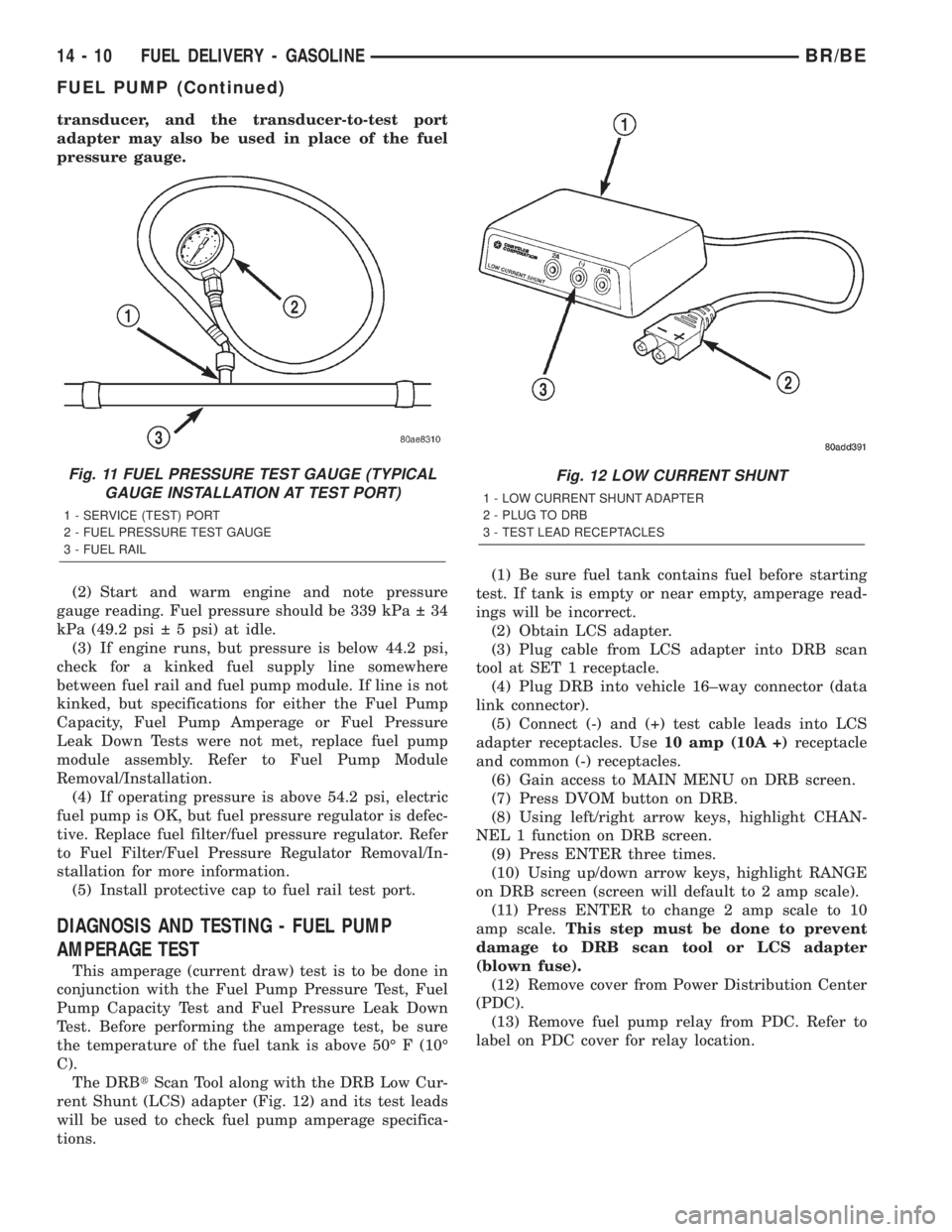
transducer, and the transducer-to-test port
adapter may also be used in place of the fuel
pressure gauge.
(2) Start and warm engine and note pressure
gauge reading. Fuel pressure should be 339 kPa 34
kPa (49.2 psi 5 psi) at idle.
(3) If engine runs, but pressure is below 44.2 psi,
check for a kinked fuel supply line somewhere
between fuel rail and fuel pump module. If line is not
kinked, but specifications for either the Fuel Pump
Capacity, Fuel Pump Amperage or Fuel Pressure
Leak Down Tests were not met, replace fuel pump
module assembly. Refer to Fuel Pump Module
Removal/Installation.
(4) If operating pressure is above 54.2 psi, electric
fuel pump is OK, but fuel pressure regulator is defec-
tive. Replace fuel filter/fuel pressure regulator. Refer
to Fuel Filter/Fuel Pressure Regulator Removal/In-
stallation for more information.
(5) Install protective cap to fuel rail test port.
DIAGNOSIS AND TESTING - FUEL PUMP
AMPERAGE TEST
This amperage (current draw) test is to be done in
conjunction with the Fuel Pump Pressure Test, Fuel
Pump Capacity Test and Fuel Pressure Leak Down
Test. Before performing the amperage test, be sure
the temperature of the fuel tank is above 50É F (10É
C).
The DRBtScan Tool along with the DRB Low Cur-
rent Shunt (LCS) adapter (Fig. 12) and its test leads
will be used to check fuel pump amperage specifica-
tions.(1) Be sure fuel tank contains fuel before starting
test. If tank is empty or near empty, amperage read-
ings will be incorrect.
(2) Obtain LCS adapter.
(3) Plug cable from LCS adapter into DRB scan
tool at SET 1 receptacle.
(4) Plug DRB into vehicle 16±way connector (data
link connector).
(5) Connect (-) and (+) test cable leads into LCS
adapter receptacles. Use10 amp (10A +)receptacle
and common (-) receptacles.
(6) Gain access to MAIN MENU on DRB screen.
(7) Press DVOM button on DRB.
(8) Using left/right arrow keys, highlight CHAN-
NEL 1 function on DRB screen.
(9) Press ENTER three times.
(10) Using up/down arrow keys, highlight RANGE
on DRB screen (screen will default to 2 amp scale).
(11) Press ENTER to change 2 amp scale to 10
amp scale.This step must be done to prevent
damage to DRB scan tool or LCS adapter
(blown fuse).
(12) Remove cover from Power Distribution Center
(PDC).
(13) Remove fuel pump relay from PDC. Refer to
label on PDC cover for relay location.
Fig. 11 FUEL PRESSURE TEST GAUGE (TYPICAL
GAUGE INSTALLATION AT TEST PORT)
1 - SERVICE (TEST) PORT
2 - FUEL PRESSURE TEST GAUGE
3 - FUEL RAIL
Fig. 12 LOW CURRENT SHUNT
1 - LOW CURRENT SHUNT ADAPTER
2 - PLUG TO DRB
3 - TEST LEAD RECEPTACLES
14 - 10 FUEL DELIVERY - GASOLINEBR/BE
FUEL PUMP (Continued)
Page 1310 of 2255
WARNING: BEFORE PROCEEDING TO NEXT STEP,
NOTE THE FUEL PUMP WILL BE ACTIVATED AND
SYSTEM PRESSURE WILL BE PRESENT. THIS WILL
OCCUR AFTER CONNECTING TEST LEADS FROM
LCS ADAPTER INTO FUEL PUMP RELAY CAVITIES.
THE FUEL PUMP WILL OPERATE EVEN WITH IGNI-
TION KEY IN OFF POSITION. BEFORE ATTACHING
TEST LEADS, BE SURE ALL FUEL LINES AND
FUEL SYSTEM COMPONENTS ARE CONNECTED.
CAUTION: To prevent possible damage to the vehi-
cle electrical system and LCS adapter, the test
leads must be connected into relay cavities exactly
as shown in following steps.
Depending upon vehicle model, year or engine con-
figuration, three different types of relays may be
used: Type-1, type-2 and type±3.
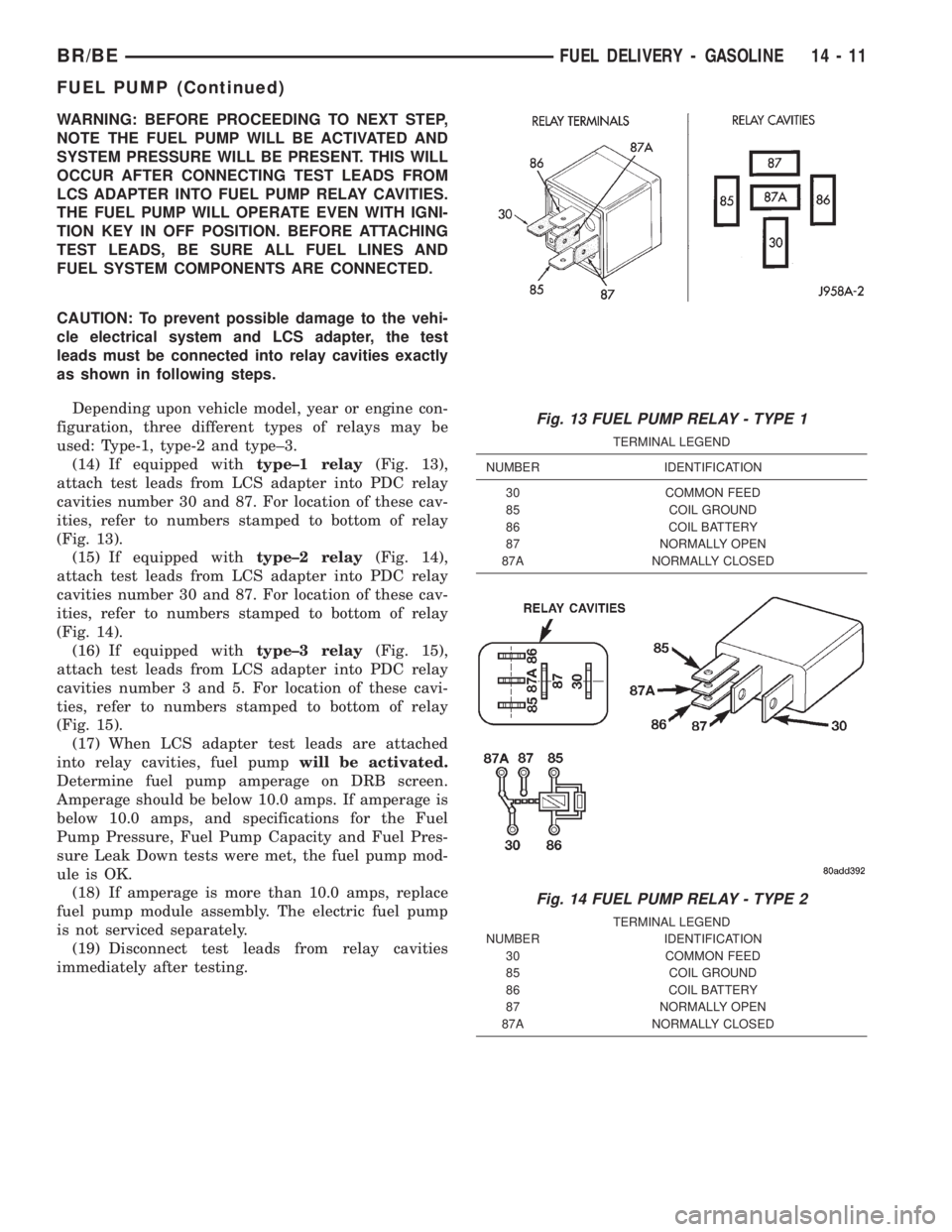
(14) If equipped withtype±1 relay(Fig. 13),
attach test leads from LCS adapter into PDC relay
cavities number 30 and 87. For location of these cav-
ities, refer to numbers stamped to bottom of relay
(Fig. 13).
(15) If equipped withtype±2 relay(Fig. 14),
attach test leads from LCS adapter into PDC relay
cavities number 30 and 87. For location of these cav-
ities, refer to numbers stamped to bottom of relay
(Fig. 14).
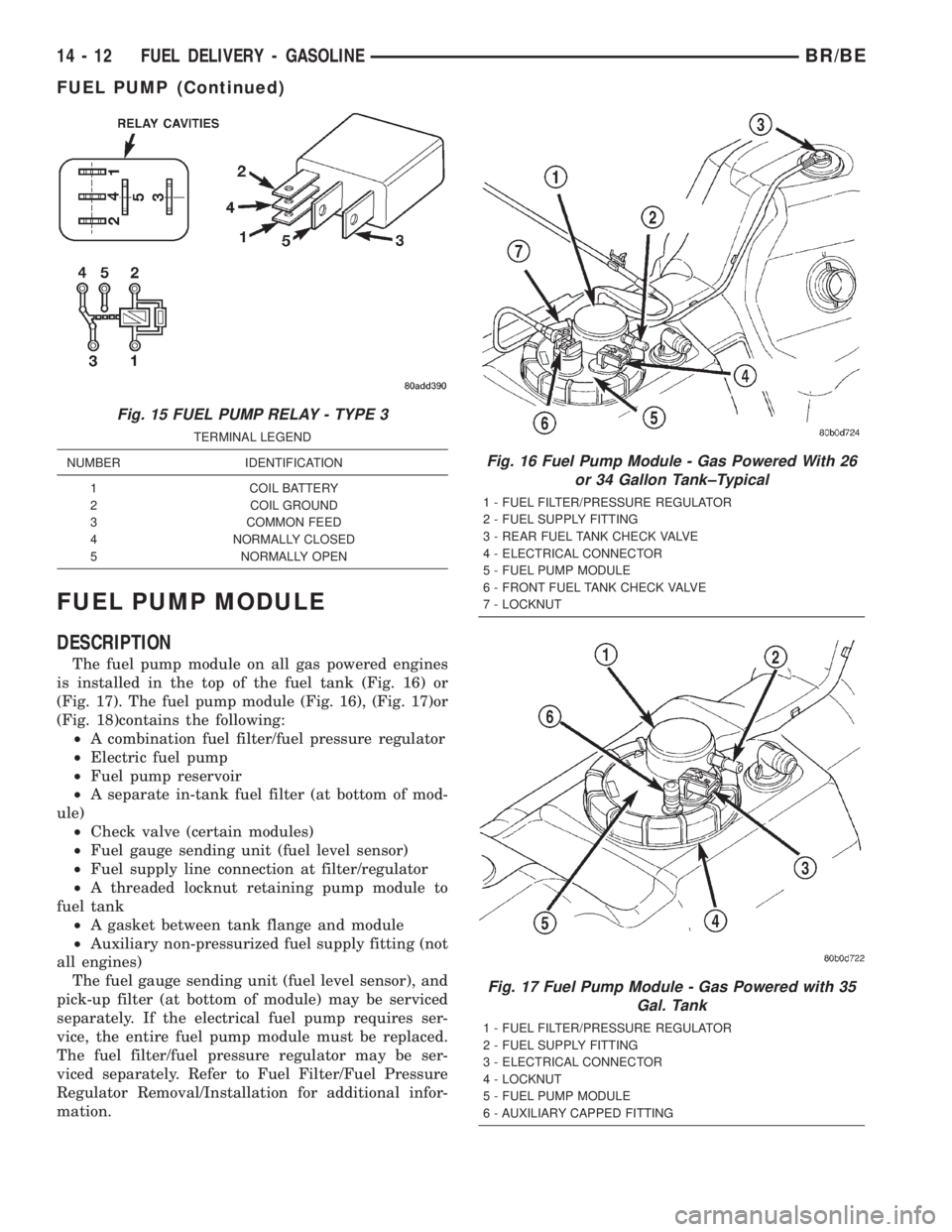
(16) If equipped withtype±3 relay(Fig. 15),
attach test leads from LCS adapter into PDC relay
cavities number 3 and 5. For location of these cavi-
ties, refer to numbers stamped to bottom of relay
(Fig. 15).
(17) When LCS adapter test leads are attached
into relay cavities, fuel pumpwill be activated.
Determine fuel pump amperage on DRB screen.
Amperage should be below 10.0 amps. If amperage is
below 10.0 amps, and specifications for the Fuel
Pump Pressure, Fuel Pump Capacity and Fuel Pres-
sure Leak Down tests were met, the fuel pump mod-
ule is OK.
(18) If amperage is more than 10.0 amps, replace
fuel pump module assembly. The electric fuel pump
is not serviced separately.
(19) Disconnect test leads from relay cavities
immediately after testing.
Fig. 13 FUEL PUMP RELAY - TYPE 1
TERMINAL LEGEND
NUMBER IDENTIFICATION
30 COMMON FEED
85 COIL GROUND
86 COIL BATTERY
87 NORMALLY OPEN
87A NORMALLY CLOSED
Fig. 14 FUEL PUMP RELAY - TYPE 2
TERMINAL LEGEND
NUMBER IDENTIFICATION
30 COMMON FEED
85 COIL GROUND
86 COIL BATTERY
87 NORMALLY OPEN
87A NORMALLY CLOSED
BR/BEFUEL DELIVERY - GASOLINE 14 - 11
FUEL PUMP (Continued)
Page 1311 of 2255
FUEL PUMP MODULE
DESCRIPTION
The fuel pump module on all gas powered engines
is installed in the top of the fuel tank (Fig. 16) or
(Fig. 17). The fuel pump module (Fig. 16), (Fig. 17)or
(Fig. 18)contains the following:
²A combination fuel filter/fuel pressure regulator
²Electric fuel pump
²Fuel pump reservoir
²A separate in-tank fuel filter (at bottom of mod-
ule)
²Check valve (certain modules)
²Fuel gauge sending unit (fuel level sensor)
²Fuel supply line connection at filter/regulator
²A threaded locknut retaining pump module to
fuel tank
²A gasket between tank flange and module
²Auxiliary non-pressurized fuel supply fitting (not
all engines)
The fuel gauge sending unit (fuel level sensor), and
pick-up filter (at bottom of module) may be serviced
separately. If the electrical fuel pump requires ser-
vice, the entire fuel pump module must be replaced.
The fuel filter/fuel pressure regulator may be ser-
viced separately. Refer to Fuel Filter/Fuel Pressure
Regulator Removal/Installation for additional infor-
mation.
Fig. 15 FUEL PUMP RELAY - TYPE 3
TERMINAL LEGEND
NUMBER IDENTIFICATION
1 COIL BATTERY
2 COIL GROUND
3 COMMON FEED
4 NORMALLY CLOSED
5 NORMALLY OPEN
Fig. 16 Fuel Pump Module - Gas Powered With 26
or 34 Gallon Tank±Typical
1 - FUEL FILTER/PRESSURE REGULATOR
2 - FUEL SUPPLY FITTING
3 - REAR FUEL TANK CHECK VALVE
4 - ELECTRICAL CONNECTOR
5 - FUEL PUMP MODULE
6 - FRONT FUEL TANK CHECK VALVE
7 - LOCKNUT
Fig. 17 Fuel Pump Module - Gas Powered with 35
Gal. Tank
1 - FUEL FILTER/PRESSURE REGULATOR
2 - FUEL SUPPLY FITTING
3 - ELECTRICAL CONNECTOR
4 - LOCKNUT
5 - FUEL PUMP MODULE
6 - AUXILIARY CAPPED FITTING
14 - 12 FUEL DELIVERY - GASOLINEBR/BE
FUEL PUMP (Continued)
Page 1312 of 2255
OPERATION
Refer to Fuel Pump, Fuel Filter/Fuel Pressure Reg-
ulator and Fuel Gauge Sending Unit.
REMOVAL
WARNING: THE FUEL SYSTEM IS UNDER A CON-
STANT PRESSURE (EVEN WITH THE ENGINE OFF).
BEFORE SERVICING THE FUEL PUMP MODULE,
THE FUEL SYSTEM PRESSURE MUST BE
RELEASED.
(1) Drain and remove fuel tank. Refer to Fuel
Tank - All Engines in the Removal/Installation sec-
tion.
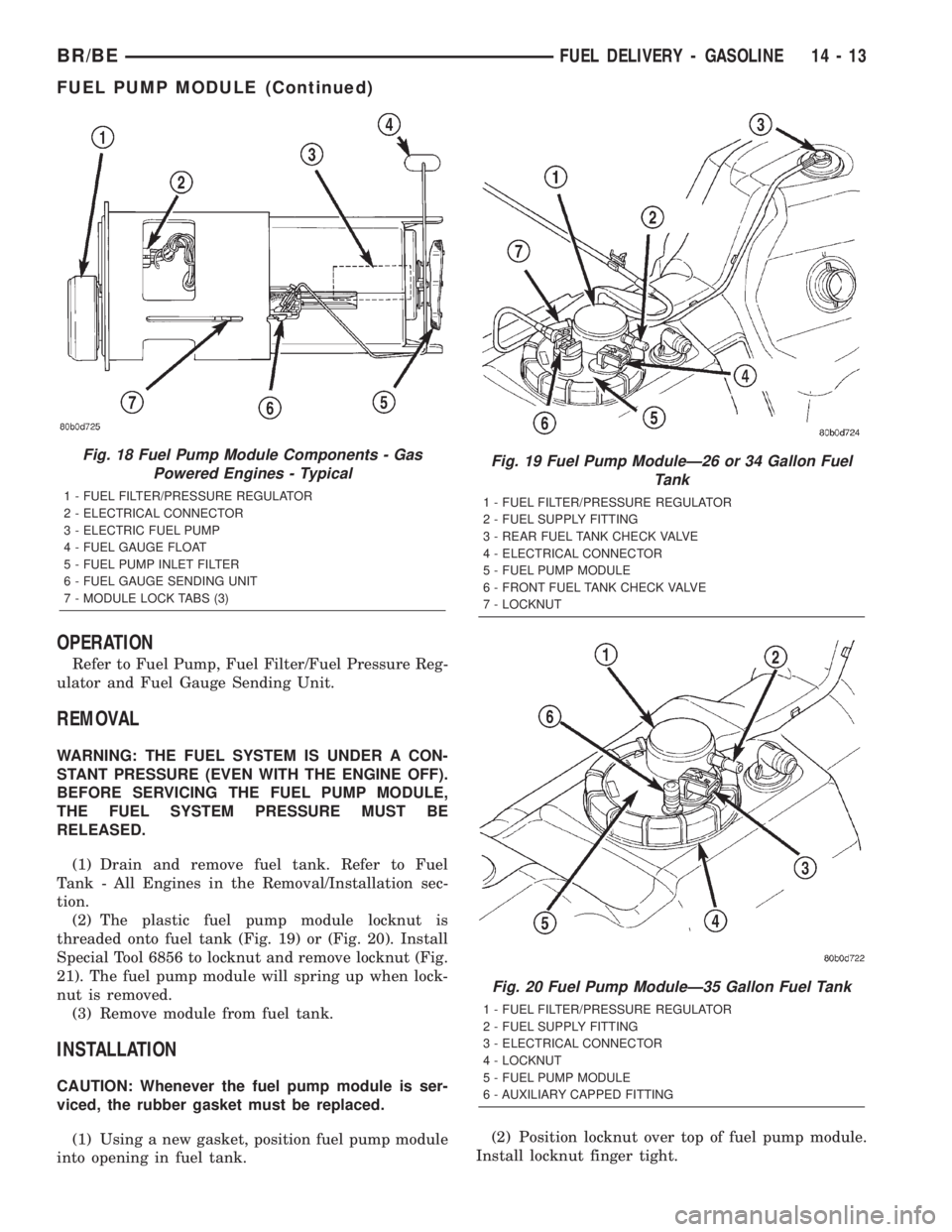
(2) The plastic fuel pump module locknut is
threaded onto fuel tank (Fig. 19) or (Fig. 20). Install
Special Tool 6856 to locknut and remove locknut (Fig.
21). The fuel pump module will spring up when lock-
nut is removed.
(3) Remove module from fuel tank.
INSTALLATION
CAUTION: Whenever the fuel pump module is ser-
viced, the rubber gasket must be replaced.
(1) Using a new gasket, position fuel pump module
into opening in fuel tank.(2) Position locknut over top of fuel pump module.
Install locknut finger tight.
Fig. 18 Fuel Pump Module Components - Gas
Powered Engines - Typical
1 - FUEL FILTER/PRESSURE REGULATOR
2 - ELECTRICAL CONNECTOR
3 - ELECTRIC FUEL PUMP
4 - FUEL GAUGE FLOAT
5 - FUEL PUMP INLET FILTER
6 - FUEL GAUGE SENDING UNIT
7 - MODULE LOCK TABS (3)
Fig. 19 Fuel Pump ModuleÐ26 or 34 Gallon Fuel
Tank
1 - FUEL FILTER/PRESSURE REGULATOR
2 - FUEL SUPPLY FITTING
3 - REAR FUEL TANK CHECK VALVE
4 - ELECTRICAL CONNECTOR
5 - FUEL PUMP MODULE
6 - FRONT FUEL TANK CHECK VALVE
7 - LOCKNUT
Fig. 20 Fuel Pump ModuleÐ35 Gallon Fuel Tank
1 - FUEL FILTER/PRESSURE REGULATOR
2 - FUEL SUPPLY FITTING
3 - ELECTRICAL CONNECTOR
4 - LOCKNUT
5 - FUEL PUMP MODULE
6 - AUXILIARY CAPPED FITTING
BR/BEFUEL DELIVERY - GASOLINE 14 - 13
FUEL PUMP MODULE (Continued)
Page 1318 of 2255
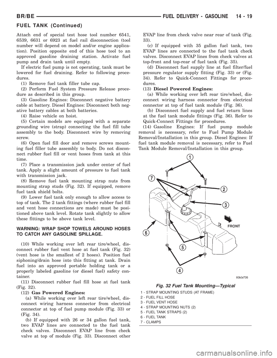
Attach end of special test hose tool number 6541,
6539, 6631 or 6923 at fuel rail disconnection (tool
number will depend on model and/or engine applica-
tion). Position opposite end of this hose tool to an
approved gasoline draining station. Activate fuel
pump and drain tank until empty.
If electric fuel pump is not operating, tank must be
lowered for fuel draining. Refer to following proce-
dures.
(1) Remove fuel tank filler tube cap.
(2) Perform Fuel System Pressure Release proce-
dure as described in this group.
(3) Gasoline Engines: Disconnect negative battery
cable at battery. Diesel Engines: Disconnect both neg-
ative battery cables at both batteries.
(4) Raise vehicle on hoist.
(5) Certain models are equipped with a separate
grounding wire (strap) connecting the fuel fill tube
assembly to the body. Disconnect wire by removing
screw.
(6) Open fuel fill door and remove screws mount-
ing fuel filler tube assembly to body. Do not discon-
nect rubber fuel fill or vent hoses from tank at this
time.
(7) Place a transmission jack under center of fuel
tank. Apply a slight amount of pressure to fuel tank
with transmission jack.
(8) Remove fuel tank mounting strap nuts from
mounting strap studs (Fig. 32). If equipped, remove
fuel tank shield bolts.
(9) Lower fuel tank only enough to allow access to
top of tank. The 2 tank fittings (where rubber fuel fill
and vent hose connections are made) must be posi-
tioned above tank level. Rotate tank slightly to allow
these fittings to be above tank level.
WARNING: WRAP SHOP TOWELS AROUND HOSES
TO CATCH ANY GASOLINE SPILLAGE.
(10) While working over left rear tire/wheel, dis-
connect rubber fuel vent hose at fuel tank (Fig. 32)
(vent hose is the smallest of 2 hoses). Position fuel
siphoning/drain hose into this fitting at tank. Drain
fuel into an approved portable holding tank or a
properly labeled gasoline (or diesel fuel) safety con-
tainer.
(11) Disconnect rubber fuel fill hose at fuel tank
(Fig. 32).
(12)Gas Powered Engines:
(a) While working over left rear tire/wheel, dis-
connect wiring harness connector from electrical
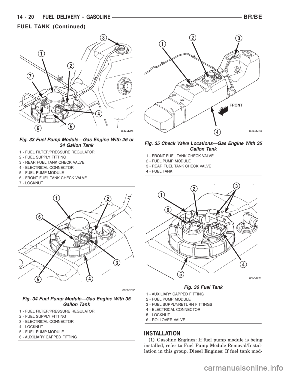
connector at top of fuel pump module (Fig. 33) or
(Fig. 34).
(b) If equipped with 26 or 34 gallon fuel tank,
two EVAP lines are connected to the fuel tank
check valves. Disconnect EVAP line from check
valve at top of module (Fig. 33). Disconnect otherEVAP line from check valve near rear of tank (Fig.
33).
(c) If equipped with 35 gallon fuel tank, two
EVAP lines are connected to the fuel tank check
valves. Disconnect EVAP lines from check valves at
top-front and top-rear of fuel tank (Fig. 35).
(d) Disconnect fuel supply line at fuel filter/fuel
pressure regulator supply fitting (Fig. 33) or (Fig.
34). Refer to Quick-Connect Fittings for proce-
dures.
(13)Diesel Powered Engines:
(a) While working over left rear tire/wheel, dis-
connect wiring harness connector from electrical
connector at top of fuel tank module (Fig. 36).
(b) Disconnect fuel supply and fuel return lines
at the fuel tank module fittings (Fig. 36). Refer to
Quick-Connect Fittings for procedures.
(14) Gasoline Engines: If fuel pump module
removal is necessary, refer to Fuel Pump Module
Removal/Installation in this group. Diesel Engines: If
fuel tank module removal is necessary, refer to Fuel
Tank Module Removal/Installation in this group.
Fig. 32 Fuel Tank MountingÐTypical
1 - STRAP MOUNTING STUDS (AT FRAME)
2 - FUEL FILL HOSE
3 - FUEL VENT HOSE
4 - STRAP MOUNTING NUTS (2)
5 - FUEL TANK STRAPS (2)
6 - FUEL TANK
7 - CLAMPS
BR/BEFUEL DELIVERY - GASOLINE 14 - 19
FUEL TANK (Continued)
Page 1319 of 2255
INSTALLATION
(1) Gasoline Engines: If fuel pump module is being
installed, refer to Fuel Pump Module Removal/Instal-
lation in this group. Diesel Engines: If fuel tank mod-
Fig. 33 Fuel Pump ModuleÐGas Engine With 26 or
34 Gallon Tank
1 - FUEL FILTER/PRESSURE REGULATOR
2 - FUEL SUPPLY FITTING
3 - REAR FUEL TANK CHECK VALVE
4 - ELECTRICAL CONNECTOR
5 - FUEL PUMP MODULE
6 - FRONT FUEL TANK CHECK VALVE
7 - LOCKNUT
Fig. 34 Fuel Pump ModuleÐGas Engine With 35
Gallon Tank
1 - FUEL FILTER/PRESSURE REGULATOR
2 - FUEL SUPPLY FITTING
3 - ELECTRICAL CONNECTOR
4 - LOCKNUT
5 - FUEL PUMP MODULE
6 - AUXILIARY CAPPED FITTING
Fig. 35 Check Valve LocationsÐGas Engine With 35
Gallon Tank
1 - FRONT FUEL TANK CHECK VALVE
2 - FUEL PUMP MODULE
3 - REAR FUEL TANK CHECK VALVE
4 - FUEL TANK
Fig. 36 Fuel Tank
1 - AUXILIARY CAPPED FITTING
2 - FUEL PUMP MODULE
3 - FUEL SUPPLY/RETURN FITTINGS
4 - ELECTRICAL CONNECTOR
5 - LOCKNUT
6 - ROLLOVER VALVE
14 - 20 FUEL DELIVERY - GASOLINEBR/BE
FUEL TANK (Continued)
Page 1320 of 2255
ule is being installed, refer to Fuel Tank Module
Removal/Installation in this group.
(2) Place fuel tank on top of transmission jack.
(3) Install rubber fill and vent lines to tank.
Tighten hose clamps to 2.3 N´m (20 in. lbs.) torque.
(4) Raise tank into position while guiding fill and
vent hoses to body. Raise tank only enough to allow
access to top of tank.
(5)Gas Powered Engines:
(a) Connect electrical connector to fuel pump
module.
(b) Connect EVAP hoses at rollover valves.
(c) Connect fuel supply line at fuel filter/fuel
pressure regulator. Refer to Quick-Connect Fittings
for procedures.
(6)Diesel Powered Engines:
(a) Connect electrical connector to fuel tank
module.
(b) Connect fuel supply and fuel return lines to
fuel tank module fittings. Refer to Quick-Connect
Fittings in this group.
(7) Connect two mounting straps and mounting
strap nuts.
(8) Tighten strap nuts to 41 N´m (30 ft. lbs.)
torque. Do not over tighten retaining strap nuts.
(9) Remove transmission jack.
(10) Connect fuel filler tube assembly to body.
(11) If equipped, connect grounding wire (strap)
and screw.
(12) Refill fuel tank and inspect all hoses and lines
for leaks.
(13) Connect negative battery cable(s) to bat-
tery(s).
FUEL TANK CHECK VALVE
DESCRIPTION
Diesel Powered Engine:One fuel tank check
valve is used. The check valve is located on the top of
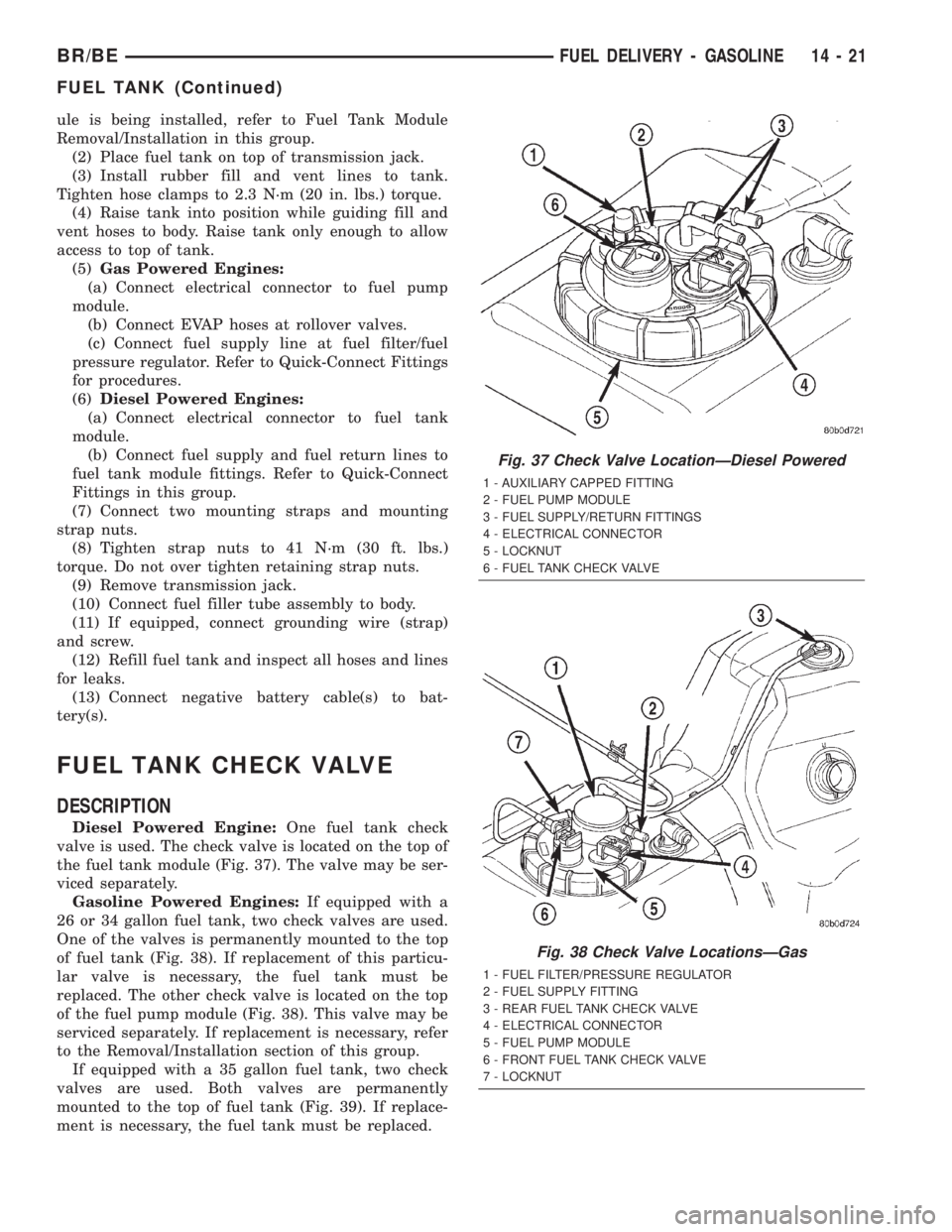
the fuel tank module (Fig. 37). The valve may be ser-
viced separately.
Gasoline Powered Engines:If equipped with a
26 or 34 gallon fuel tank, two check valves are used.
One of the valves is permanently mounted to the top
of fuel tank (Fig. 38). If replacement of this particu-
lar valve is necessary, the fuel tank must be
replaced. The other check valve is located on the top
of the fuel pump module (Fig. 38). This valve may be
serviced separately. If replacement is necessary, refer
to the Removal/Installation section of this group.
If equipped with a 35 gallon fuel tank, two check
valves are used. Both valves are permanently
mounted to the top of fuel tank (Fig. 39). If replace-
ment is necessary, the fuel tank must be replaced.
Fig. 37 Check Valve LocationÐDiesel Powered
1 - AUXILIARY CAPPED FITTING
2 - FUEL PUMP MODULE
3 - FUEL SUPPLY/RETURN FITTINGS
4 - ELECTRICAL CONNECTOR
5 - LOCKNUT
6 - FUEL TANK CHECK VALVE
Fig. 38 Check Valve LocationsÐGas
1 - FUEL FILTER/PRESSURE REGULATOR
2 - FUEL SUPPLY FITTING
3 - REAR FUEL TANK CHECK VALVE
4 - ELECTRICAL CONNECTOR
5 - FUEL PUMP MODULE
6 - FRONT FUEL TANK CHECK VALVE
7 - LOCKNUT
BR/BEFUEL DELIVERY - GASOLINE 14 - 21
FUEL TANK (Continued)
Page 1321 of 2255
REMOVAL
WARNING: THE FUEL SYSTEM IS UNDER A CON-
STANT PRESSURE (EVEN WITH THE ENGINE OFF).
BEFORE SERVICING THE CHECK VALVE, FUEL
SYSTEM PRESSURE MUST BE RELEASED (GASO-
LINE POWERED ENGINES ONLY). REFER TO THE
FUEL PRESSURE RELEASE PROCEDURE IN
GROUP 14, FUEL SYSTEM.
(1)Diesel Powered Engine:One checkr valve is
used. The valve is located on top of fuel tank module
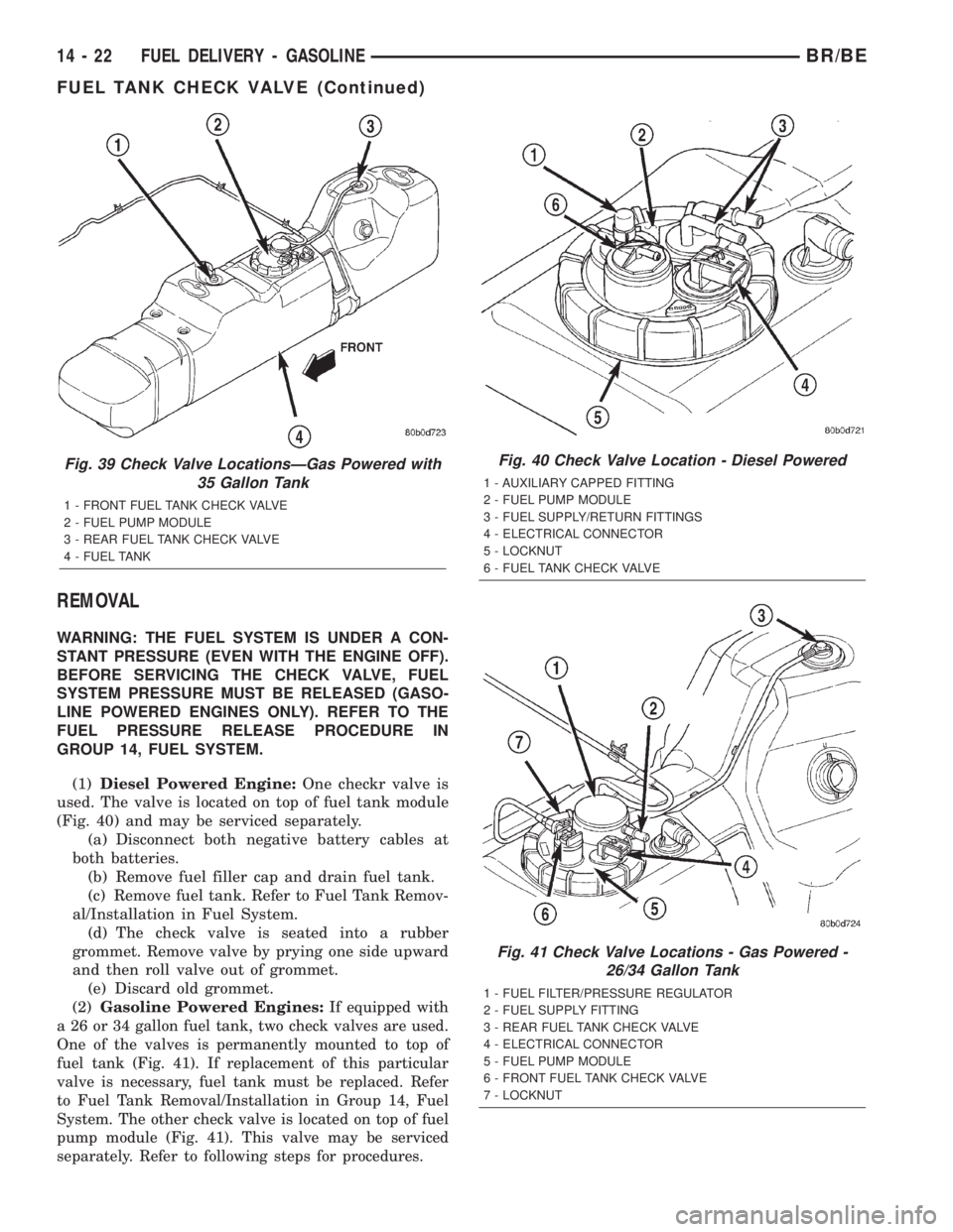
(Fig. 40) and may be serviced separately.
(a) Disconnect both negative battery cables at
both batteries.
(b) Remove fuel filler cap and drain fuel tank.
(c) Remove fuel tank. Refer to Fuel Tank Remov-
al/Installation in Fuel System.
(d) The check valve is seated into a rubber
grommet. Remove valve by prying one side upward
and then roll valve out of grommet.
(e) Discard old grommet.
(2)Gasoline Powered Engines:
If equipped with
a 26 or 34 gallon fuel tank, two check valves are used.
One of the valves is permanently mounted to top of
fuel tank (Fig. 41). If replacement of this particular
valve is necessary, fuel tank must be replaced. Refer
to Fuel Tank Removal/Installation in Group 14, Fuel
System. The other check valve is located on top of fuel
pump module (Fig. 41). This valve may be serviced
separately. Refer to following steps for procedures.
Fig. 39 Check Valve LocationsÐGas Powered with
35 Gallon Tank
1 - FRONT FUEL TANK CHECK VALVE
2 - FUEL PUMP MODULE
3 - REAR FUEL TANK CHECK VALVE
4 - FUEL TANK
Fig. 40 Check Valve Location - Diesel Powered
1 - AUXILIARY CAPPED FITTING
2 - FUEL PUMP MODULE
3 - FUEL SUPPLY/RETURN FITTINGS
4 - ELECTRICAL CONNECTOR
5 - LOCKNUT
6 - FUEL TANK CHECK VALVE
Fig. 41 Check Valve Locations - Gas Powered -
26/34 Gallon Tank
1 - FUEL FILTER/PRESSURE REGULATOR
2 - FUEL SUPPLY FITTING
3 - REAR FUEL TANK CHECK VALVE
4 - ELECTRICAL CONNECTOR
5 - FUEL PUMP MODULE
6 - FRONT FUEL TANK CHECK VALVE
7 - LOCKNUT
14 - 22 FUEL DELIVERY - GASOLINEBR/BE
FUEL TANK CHECK VALVE (Continued)