2002 DODGE RAM fuel cap
[x] Cancel search: fuel capPage 1272 of 2255
SPECIFICATIONS
TORQUE
DESCRIPTION N´m Ft. In.
Lbs. Lbs.
Adjusting StrapÐBolt 23 Ð 200
Air Heater Power SupplyÐ
Nuts14 Ð 124
Air Inlet HousingÐBolts 24 18 Ð
Cab Heater Supply/Return
LineÐNuts24 18 Ð
Exhaust ClampÐNuts 48 35 Ð
Exhaust Manifold to Cylinder
HeadÐBolts
(Diesel Engine) 43 32 Ð
Exhaust Manifold to Cylinder
HeadÐBolts
(5.9L) 31 23 Ð
Exhaust Manifold to Cylinder
HeadÐBolts
(8.0L) 22 Ð 195
Exhaust Pipe to ManifoldÐ
Bolts31 23 Ð
Generator MountingÐBolts 41 30 Ð
Charge Air Cooler
MountingÐBolts2Ð17
Charge Air Cooler DuctÐ
Nuts8Ð72
Heat ShieldÐNuts and Bolts 11 Ð 100
Turbocharger MountingÐ
Nuts32 24 Ð
Turbocharger Oil Drain
TubeÐBolts24 18 Ð
Turbocharger Oil Supply
LineÐFitting15 Ð 133
Turbocharger V-Band
ClampÐNut9Ð75
CATALYTIC CONVERTER -
3.9L/5.2L/5.9L
DESCRIPTION
The stainless steel catalytic converter is located
under the vehicle, integral to the exhaust pipe(s).
OPERATION
The catalytic converter captures and burns any
unburned fuel mixture exiting the combustion cham-
bers during the exhaust stroke of the engine. This
process aids in reducing emissions output.
REMOVAL
(1) Raise and support vehicle.
(2) Saturate the bolts and nuts with heat valve
lubricant. Allow 5 minutes for penetration.
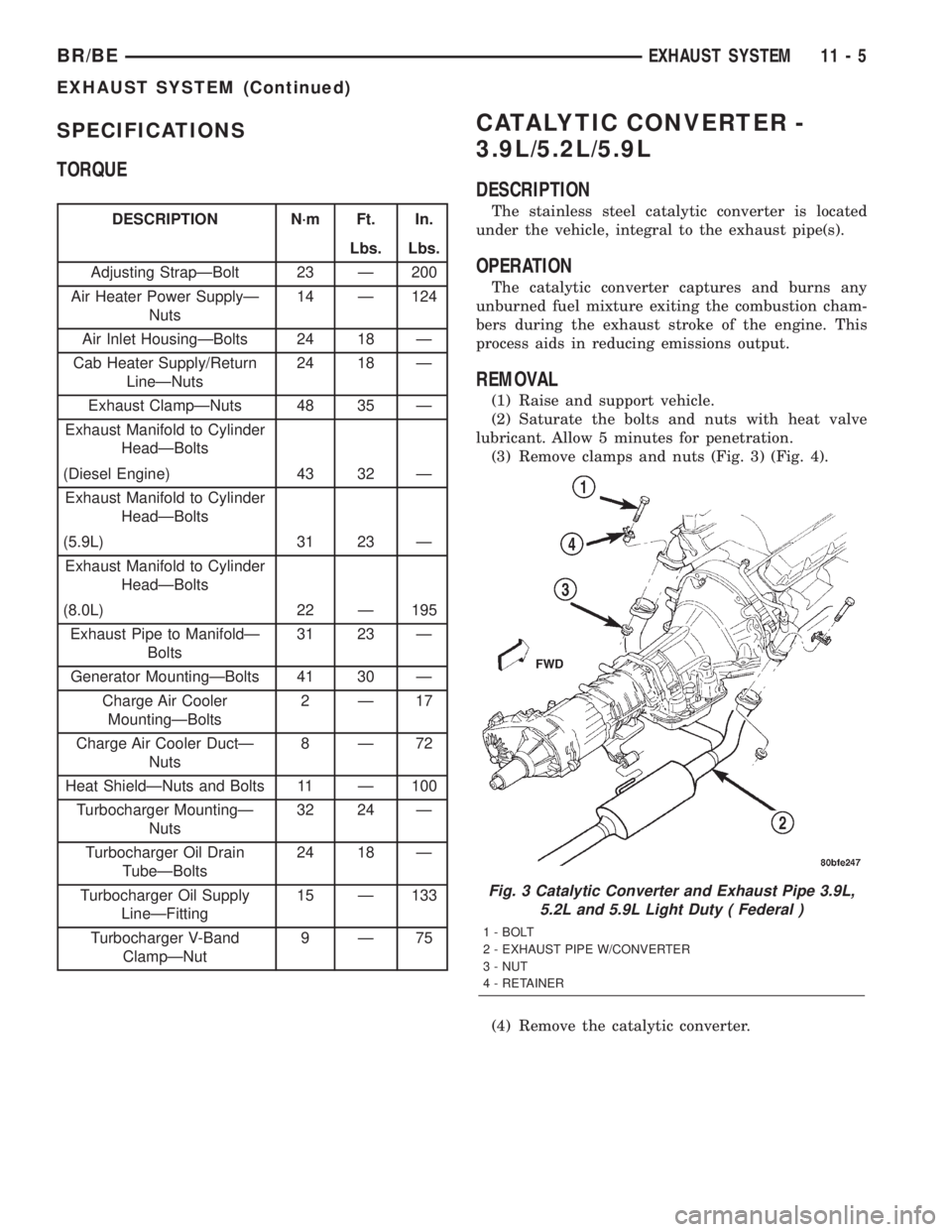
(3) Remove clamps and nuts (Fig. 3) (Fig. 4).
(4) Remove the catalytic converter.
Fig. 3 Catalytic Converter and Exhaust Pipe 3.9L,
5.2L and 5.9L Light Duty ( Federal )
1 - BOLT
2 - EXHAUST PIPE W/CONVERTER
3 - NUT
4 - RETAINER
BR/BEEXHAUST SYSTEM 11 - 5
EXHAUST SYSTEM (Continued)
Page 1273 of 2255
INSPECTION
Look at the stainless steel body of the converter,
inspect for bulging or other distortion that could be a
result of overheating. If the converter has a heat
shield attached make sure it is not bent or loose.
If you suspect internal damage to the catalyst, tap-
ping the bottom of the catalyst with a rubber mallet
may indicate a damaged core.
INSTALLATION
(1) Assemble converter and clamps loosely in
place.
(2) Install the exhaust pipe onto exhaust mani-
folds, tighten 31 N´m (23 ft. lbs.).
(3) Tighten all clamp nuts to 48 N´m (35 ft. lbs.)
torque.
(4) Lower the vehicle.
(5) Start the engine and inspect for exhaust leaks
and exhaust system contact with the body panels. A
minimum of 25.4 mm (1.0 in.) is required between
exhaust system components and body/frame parts.
Adjust the alignment, if needed.
CATALYTIC CONVERTER - 5.9L
HD/8.0L
DESCRIPTION
The stainless steel catalytic converter is located
under the vehicle, attached to the exhaust pipe(s).
OPERATION
The catalytic converter captures and burns any
unburned fuel mixture exiting the combustion cham-
bers during the exhaust stroke of the engine. This
process aids in reducing emissions output.
REMOVAL
(1) Raise and support vehicle.
(2) Saturate the bolts and nuts with heat valve
lubricant. Allow 5 minutes for penetration.
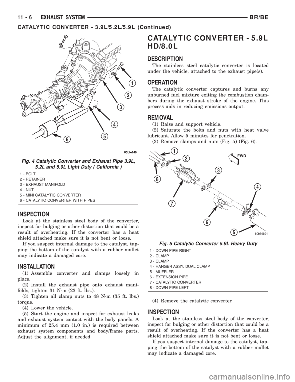
(3) Remove clamps and nuts (Fig. 5) (Fig. 6).
(4) Remove the catalytic converter.
INSPECTION
Look at the stainless steel body of the converter,
inspect for bulging or other distortion that could be a
result of overheating. If the converter has a heat
shield attached make sure it is not bent or loose.
If you suspect internal damage to the catalyst, tap-
ping the bottom of the catalyst with a rubber mallet
may indicate a damaged core.
Fig. 4 Catalytic Converter and Exhaust Pipe 3.9L,
5.2L and 5.9L Light Duty ( California )
1 - BOLT
2 - RETAINER
3 - EXHAUST MANIFOLD
4 - NUT
5 - MINI CATALYTIC CONVERTER
6 - CATALYTIC CONVERTER WITH PIPES
Fig. 5 Catalytic Converter 5.9L Heavy Duty
1 - DOWN PIPE RIGHT
2 - CLAMP
3 - CLAMP
4 - HANGER ASSY. DUAL CLAMP
5 - MUFFLER
6 - EXTENSION PIPE
7 - CATALYTIC CONVERTER
8 - DOWN PIPE LEFT
11 - 6 EXHAUST SYSTEMBR/BE
CATALYTIC CONVERTER - 3.9L/5.2L/5.9L (Continued)
Page 1300 of 2255
FUEL SYSTEM
TABLE OF CONTENTS
page page
FUEL DELIVERY - GASOLINE...............1
FUEL INJECTION - GASOLINE..............28FUEL DELIVERY - DIESEL.................54
FUEL INJECTION - DIESEL................91
FUEL DELIVERY - GASOLINE
TABLE OF CONTENTS
page page
FUEL DELIVERY - GASOLINE
DESCRIPTION - FUEL DELIVERY SYSTEM....2
OPERATION - FUEL DELIVERY SYSTEM......2
DIAGNOSIS AND TESTING - FUEL
PRESSURE LEAK DOWN TEST...........2
STANDARD PROCEDURE - FUEL SYSTEM
PRESSURE RELEASE...................3
SPECIFICATIONS
SPECIFICATIONS - FUEL SYSTEM
PRESSURE - GAS ENGINES..............3
SPECIFICATIONS - TORQUE - FUEL
DELIVERY............................4
SPECIAL TOOLS
FUEL SYSTEM........................4
FUEL FILTER/PRESSURE REGULATOR
DESCRIPTION..........................5
OPERATION............................5
REMOVAL.............................5
INSTALLATION..........................7
FUEL LEVEL SENDING UNIT / SENSOR
DESCRIPTION..........................7
OPERATION............................7
DIAGNOSIS AND TESTING - FUEL GAUGE
SENDING UNIT........................7
REMOVAL.............................7
INSTALLATION..........................8
FUEL LINES
DESCRIPTION..........................8
FUEL PUMP
DESCRIPTION..........................9
OPERATION............................9
DIAGNOSIS AND TESTING
DIAGNOSIS AND TESTING - FUEL PUMP
CAPACITY TEST.......................9
DIAGNOSIS AND TESTING - FUEL PUMP
PRESSURE TEST......................9DIAGNOSIS AND TESTING - FUEL PUMP
AMPERAGE TEST.....................10
FUEL PUMP MODULE
DESCRIPTION.........................12
OPERATION...........................13
REMOVAL.............................13
INSTALLATION.........................13
FUEL RAIL
DESCRIPTION
DESCRIPTION - 5.9L...................14
DESCRIPTION - 8.0L...................14
OPERATION
OPERATION - 5.9L....................14
OPERATION - 8.0L....................15
REMOVAL
REMOVAL - 5.9L......................15
REMOVAL - 8.0L......................16
INSTALLATION
INSTALLATION - 5.9L..................17
INSTALLATION - 8.0L..................18
FUEL TANK
DESCRIPTION.........................18
OPERATION...........................18
REMOVAL.............................18
INSTALLATION.........................20
FUEL TANK CHECK VALVE
DESCRIPTION.........................21
REMOVAL.............................22
INSTALLATION.........................23
INLET FILTER
REMOVAL.............................23
INSTALLATION.........................23
QUICK CONNECT FITTING
DESCRIPTION.........................24
STANDARD PROCEDURE - QUICK-CONNECT
FITTINGS...........................24
BR/BEFUEL SYSTEM 14 - 1
Page 1301 of 2255
FUEL DELIVERY - GASOLINE
DESCRIPTION - FUEL DELIVERY SYSTEM
The fuel delivery system consists of:
²the fuel pump module containing the electric
fuel pump, fuel filter/fuel pressure regulator, rollover
valve (certain modules), fuel gauge sending unit (fuel
level sensor) and a separate fuel filter located at bot-
tom of pump module
²fuel tubes/lines/hoses
²quick-connect fittings
²fuel injector rail
²fuel injectors
²fuel tank
²fuel tank filler/vent tube assembly
²fuel tank filler tube cap
²accelerator pedal
²throttle cable
OPERATION - FUEL DELIVERY SYSTEM
Fuel is returned through the fuel pump module
and back into the fuel tank through the fuel filter/
fuel pressure regulator. A separate fuel return line
from the engine to the tank is not used with any gas-
oline powered engine.
The fuel tank assembly consists of: the fuel tank,
fuel pump module assembly, fuel pump module lock-
nut/gasket and fuel tank check valve(s) (refer to 25,
Emission Control System for Fuel Tank Check Valve
information).
A fuel filler/vent tube assembly using a pressure/
vacuum, 1/4 turn fuel filler cap is used. The fuel
filler tube contains a flap door located below the fuel
fill cap.
Also to be considered part of the fuel system is the
evaporation control system. This is designed to
reduce the emission of fuel vapors into the atmo-
sphere. The description and function of the Evapora-
tive Control System is found in 25, Emission Control
Systems.
Both fuel filters (at bottom of fuel pump module
and within fuel pressure regulator) are designed for
extended service. They do not require normal sched-
uled maintenance. Filters should only be replaced if
a diagnostic procedure indicates to do so.
DIAGNOSIS AND TESTING - FUEL PRESSURE
LEAK DOWN TEST
Use this test in conjunction with the Fuel Pump
Pressure Test and Fuel Pump Capacity Test.
Check Valve Operation:The electric fuel pump
outlet contains a one-way check valve to prevent fuel
flow back into the tank and to maintain fuel supply
line pressure (engine warm) when pump is not oper-
ational. It is also used to keep the fuel supply linefull of gasoline when pump is not operational. After
the vehicle has cooled down, fuel pressure may drop
to 0 psi (cold fluid contracts), but liquid gasoline will
remain in fuel supply line between the check valve
and fuel injectors.Fuel pressure that has
dropped to 0 psi on a cooled down vehicle
(engine off) is a normal condition.When the elec-
tric fuel pump is activated, fuel pressure should
immediately(1±2 seconds) rise to specification.
Abnormally long periods of cranking to restart a
hotengine that has been shut down for a short
period of time may be caused by:
²Fuel pressure bleeding past a fuel injector(s).
²Fuel pressure bleeding past the check valve in
the fuel pump module.
(1) Disconnect the fuel inlet line at fuel rail. Refer
to Fuel Tubes/Lines/Hoses and Clamps for proce-
dures. On some engines, air cleaner housing removal
may be necessary before fuel line disconnection.
(2) Obtain correct Fuel Line Pressure Test Adapter
Tool Hose. Tool number 6539 is used for 5/16º fuel
lines and tool number 6631 is used for 3/8º fuel lines.
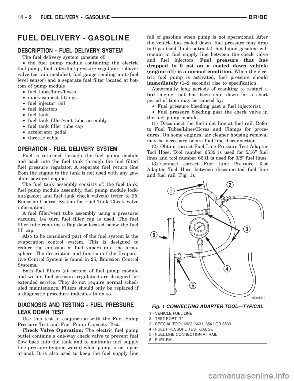
(3) Connect correct Fuel Line Pressure Test
Adapter Tool Hose between disconnected fuel line
and fuel rail (Fig. 1).
Fig. 1 CONNECTING ADAPTER TOOLÐTYPICAL
1 - VEHICLE FUEL LINE
2 - TEST PORT ªTº
3 - SPECIAL TOOL 6923, 6631, 6541 OR 6539
4 - FUEL PRESSURE TEST GAUGE
5 - FUEL LINE CONNECTION AT RAIL
6 - FUEL RAIL
14 - 2 FUEL DELIVERY - GASOLINEBR/BE
Page 1302 of 2255
(4) Connect the 0-414 kPa (0-60 psi) fuel pressure
test gauge (from Gauge Set 5069) to the test port on
the appropriate Adaptor Tool.The DRBtIII Scan
Tool along with the PEP module, the 500 psi
pressure transducer, and the transducer-to-test
port adapter may also be used in place of the
fuel pressure gauge.
The fittings on both tools must be in good
condition and free from any small leaks before
performing the proceeding test.
(5) Start engine and bring to normal operating
temperature.
(6) Observe test gauge. Normal operating pressure
should be 339 kPa +/±34 kPa (49.2 psi +/±5 psi).
(7) Shut engine off.
(8) Pressure should not fall below30 psi for five
minutes.
(9) If pressure falls below 30 psi, it must be deter-
mined if a fuel injector, the check valve within the
fuel pump module, or a fuel tube/line is leaking.
(10) Again, start engine and bring to normal oper-
ating temperature.
(11) Shut engine off.
(12)Testing for fuel injector or fuel rail leak-
age:Clamp off the rubber hose portion of Adaptor
Tool between the fuel rail and the test port ªTº on
Adapter Tool. If pressure now holds at or above 30
psi, a fuel injector or the fuel rail is leaking.
(13)Testing for fuel pump check valve, filter/
regulator check valve or fuel tube/line leakage:
Clamp off the rubber hose portion of Adaptor Tool
between the vehicle fuel line and test port ªTº on
Adapter Tool. If pressure now holds at or above 30
psi, a leak may be found at a fuel tube/line. If no
leaks are found at fuel tubes or lines, one of the
check valves in either the electric fuel pump or filter/
regulator may be leaking.
Note: A quick loss of pressure usually indicates a
defective check valve in the filter/regulator. A slow
loss of pressure usually indicates a defective check
valve in the electric fuel pump.
The electric fuel pump is not serviced separately.
Replace the fuel pump module assembly. The filter/
regulator may be replaced separately on certain
applications. Refer to Fuel Filter/Fuel Pressure Reg-
ulator Removal/Installation for additional informa-
tion.
STANDARD PROCEDURE - FUEL SYSTEM
PRESSURE RELEASE
Use following procedure if the fuel injector
rail is, or is not equipped with a fuel pressure
test port.
(1) Remove fuel fill cap.(2) Remove fuel pump relay from Power Distribu-
tion Center (PDC). For location of relay, refer to label
on underside of PDC cover.
(3) Start and run engine until it stalls.
(4) Attempt restarting engine until it will no
longer run.
(5) Turn ignition key to OFF position.
CAUTION: Steps 1, 2, 3 and 4 must be performed to
relieve high pressure fuel from within fuel rail. Do
not attempt to use following steps to relieve this
pressure as excessive fuel will be forced into a cyl-
inder chamber.
(6) Unplug connector from any fuel injector.
(7) Attach one end of a jumper wire with alligator
clips (18 gauge or smaller) to either injector terminal.
(8) Connect other end of jumper wire to positive
side of battery.
(9) Connect one end of a second jumper wire to
remaining injector terminal.
CAUTION: Powering an injector for more than a few
seconds will permanently damage the injector.
(10) Momentarily touch other end of jumper wire
to negative terminal of battery for no more than a
few seconds.
(11) Place a rag or towel below fuel line quick-con-
nect fitting at fuel rail.
(12) Disconnect quick-connect fitting at fuel rail.
Refer to Quick-Connect Fittings.
(13) Return fuel pump relay to PDC.
(14) One or more Diagnostic Trouble Codes (DTC's)
may have been stored in PCM memory due to fuel
pump relay removal. The DRBtscan tool must be
used to erase a DTC.
SPECIFICATIONS
SPECIFICATIONS - FUEL SYSTEM PRESSURE -
GAS ENGINES
All Gasoline Powered Engines:339 kPa 34
kPa (49.2 psi 5 psi)
BR/BEFUEL DELIVERY - GASOLINE 14 - 3
FUEL DELIVERY - GASOLINE (Continued)
Page 1305 of 2255

(2) The fuel filter/regulator is pressed into a rub-
ber grommet. Remove by twisting and pulling
straight up (Fig. 6).
CAUTION: Do not pull filter/regulator more than
three inches from fuel pump module. Damage to
coiled fuel tube (line) may result.
(3) Gently cut old fuel tube (line) clamp (Fig. 7)
taking care not to damage plastic fuel tube. Remove
and discard old fuel tube clamp.
(4) Remove plastic fuel tube from filter/regulator
by gently pulling downward. Remove filter/regulator
from fuel pump module.
Fig. 4 Filter/Regulator LocationÐWith 26 or 34
Gallon Fuel Tank
1 - FUEL FILTER/PRESSURE REGULATOR
2 - FUEL SUPPLY FITTING
3 - REAR FUEL TANK CHECK VALVE
4 - ELECTRICAL CONNECTOR
5 - FUEL PUMP MODULE
6 - FRONT FUEL TANK CHECK VALVE
7 - LOCKNUT
Fig. 5 Filter/Regulator LocationÐWith 35 Gallon
Fuel Tank
1 - FUEL FILTER/PRESSURE REGULATOR
2 - FUEL SUPPLY FITTING
3 - ELECTRICAL CONNECTOR
4 - LOCKNUT
5 - FUEL PUMP MODULE
6 - AUXILIARY CAPPED FITTING
Fig. 6 Filter/Regulator Removal and InstallationÐ
TYPICAL
1 - RUBBER GROMMET
2 - FUEL FILTER/FUEL PRESSURE REGULATOR
Fig. 7 Fuel Tube and ClampÐTYPICAL
1 - FUEL FILTER/FUEL PRESSURE REGULATOR
2 - TUBE CLAMP
3 - FUEL TUBE
14 - 6 FUEL DELIVERY - GASOLINEBR/BE
FUEL FILTER/PRESSURE REGULATOR (Continued)
Page 1306 of 2255
INSTALLATION
(1) Install a new clamp over plastic fuel tube.
(2) Install filter/regulator to fuel tube. Rotate fil-
ter/regulator in fuel tube (line) (Fig. 8) until it is
pointed to drivers side of vehicle (Fig. 4) or (Fig. 5).
(3) Tighten line clamp to fuel line using special
Hose Clamp Pliers number C-4124 or equivalent
(Fig. 8) .Do not use conventional side cutters to
tighten this type of clamp.
(4) Press filter/regulator (by hand) into rubber
grommet. The assembly should be pointed towards
drivers side of vehicle (Fig. 4) or (Fig. 5) .
(5) Install fuel tank. Refer to Fuel Tank Removal/
Installation.
(6) Check for fuel leaks.
FUEL LEVEL SENDING UNIT /
SENSOR
DESCRIPTION
The fuel gauge sending unit (fuel level sensor) is
attached to the side of the fuel pump module. The
sending unit consists of a float, an arm, and a vari-
able resistor track (card).
OPERATION
The fuel pump module has 4 different circuits
(wires). Two of these circuits are used for the fuel
gauge sending unit for fuel gauge operation, and for
certain OBD II emission requirements. The other 2
wires are used for electric fuel pump operation.
For Fuel Gauge Operation:A constant current
source of about 32 mA is supplied to the resistortrack on the fuel gauge sending unit. This is fed
directly from the Powertrain Control Module (PCM).
The resistor track is used to vary the voltage depend-
ing on fuel tank float level. As fuel level increases,
the float and arm move up, which decreases voltage.
As fuel level decreases, the float and arm move
down, which increases voltage. The varied voltage
signal is returned back to the PCM through the sen-
sor return circuit. Output voltages will vary from
about .6 volts at FULL, to about 8.6 volts at EMPTY
(Jeep models), or, about 7.0 volts at EMPTY (Dodge
Truck models).NOTE: For diagnostic purposes,
this voltage can only be verified with the fuel
gauge sending unit circuit closed (i.e. having all
of the sending units electrical connectors con-
nected).
Both of the electrical circuits between the fuel
gauge sending unit and the PCM are hard-wired (not
multi-plexed). After the voltage signal is sent from
the resistor track, and back to the PCM, the PCM
will interpret the resistance (voltage) data and send
a message across the multi-plex bus circuits to the
instrument panel cluster. Here it is translated into
the appropriate fuel gauge level reading. Refer to
Instrument Panel for additional information.
For OBD II Emission Monitor Requirements:
The PCM will monitor the voltage output sent from
the resistor track on the sending unit to indicate fuel
level. The purpose of this feature is to prevent the
OBD II system from recording/setting false misfire
and fuel system monitor diagnostic trouble codes.
The feature is activated if the fuel level in the tank
is less than approximately 15 percent of its rated
capacity. If equipped with a Leak Detection Pump
(EVAP system monitor), this feature will also be acti-
vated if the fuel level in the tank is more than
approximately 85 percent of its rated capacity.
DIAGNOSIS AND TESTING - FUEL GAUGE
SENDING UNIT
The fuel gauge sending unit contains a variable
resistor (track). As the float moves up or down, elec-
trical resistance will change. Refer to Instrument
Panel and Gauges under Electrical for Fuel Gauge
testing. To test the gauge sending unit only, it must
be removed from vehicle. The unit is part of the fuel
pump module. Refer to Fuel Pump Module Removal/
Installation for procedures. Measure the resistance
across the sending unit terminals. With float in up
position, resistance should be 20 ohms 6 ohms. With
float in down position, resistance should be 220 ohms
6 ohms.
REMOVAL
The fuel gauge sending unit (fuel level sensor) and
float assembly is located on the side of fuel pump
Fig. 8 Tightening Fuel Tube ClampÐTYPICAL
1 - TOOL C-4124
2 - TUBE CLAMP
3 - FUEL TUBE
BR/BEFUEL DELIVERY - GASOLINE 14 - 7
FUEL FILTER/PRESSURE REGULATOR (Continued)
Page 1308 of 2255
FUEL PUMP
DESCRIPTION
The electric fuel pump is located inside of the fuel
pump module. A 12 volt, permanent magnet, electric
motor powers the fuel pump. The electric fuel pump
is not a separate, serviceable component.
OPERATION
Voltage to operate the electric pump is supplied
through the fuel pump relay.
Fuel is drawn in through a filter at the bottom of
the module and pushed through the electric motor
gearset to the pump outlet.
Check Valve Operation:The pump outlet con-
tains a one-way check valve to prevent fuel flow back
into the tank and to maintain fuel supply line pres-
sure (engine warm) when pump is not operational. It
is also used to keep the fuel supply line full of gaso-
line when pump is not operational. After the vehicle
has cooled down, fuel pressure may drop to 0 psi
(cold fluid contracts), but liquid gasoline will remain
in fuel supply line between the check valve and fuel
injectors.Fuel pressure that has dropped to 0
psi on a cooled down vehicle (engine off) is a
normal condition.Refer to the Fuel Pressure Leak
Down Test for more information.
The electric fuel pump is not a separate, service-
able component.
DIAGNOSIS AND TESTING
DIAGNOSIS AND TESTING - FUEL PUMP
CAPACITY TEST
Before performing this test, verify fuel pump
pressure. Refer to Fuel Pump Pressure Test.
Use this test in conjunction with the Fuel Pres-
sure Leak Down Test.
(1) Release fuel system pressure. Refer to Fuel
Pressure Release Procedure.
(2) Disconnect fuel supply line at fuel rail. Refer to
Quick-Connect Fittings. Some engines may require
air cleaner housing removal before line disconnection.
(3) Obtain correct Fuel Line Pressure Test Adapter
Tool Hose. Tool number 6539 is used for 5/16º fuel
lines and tool number 6631 is used for 3/8º fuel lines.
(4) Connect correct Fuel Line Pressure Test
Adapter Tool Hose into disconnected fuel supply line.
Insert other end of Adaptor Tool Hose into a gradu-
ated container.
(5) Remove fuel fill cap.
(6) To activate fuel pump and pressurize system,
obtain DRBtscan tool and actuate ASD Fuel System
Test.(7) A good fuel pump will deliver at least 1/4 liter
of fuel in 7 seconds. Do not operate fuel pump for
longer than 7 seconds with fuel line disconnected as
fuel pump module reservoir may run empty.
(a) If capacity is lower than specification, but
fuel pump can be heard operating through fuel fill
cap opening, check for a kinked/damaged fuel sup-
ply line somewhere between fuel rail and fuel
pump module.
(b) If line is not kinked/damaged, and fuel pres-
sure is OK, but capacity is low, replace fuel filter/
fuel pressure regulator. The filter/regulator may be
serviced separately on certain applications. Refer
to Fuel Filter/Fuel Pressure Regulator Removal/In-
stallation for additional information.
(c) If both fuel pressure and capacity are low,
replace fuel pump module assembly. Refer to Fuel
Pump Module Removal/Installation.
DIAGNOSIS AND TESTING - FUEL PUMP
PRESSURE TEST
Use this test in conjunction with the Fuel Pump
Capacity Test, Fuel Pressure Leak Down Test and
Fuel Pump Amperage Test found elsewhere in this
group.
Check Valve Operation:The electric fuel pump
outlet contains a one-way check valve to prevent fuel
flow back into the tank and to maintain fuel supply
line pressure (engine warm) when pump is not oper-
ational. It is also used to keep the fuel supply line
full of gasoline when pump is not operational. After
the vehicle has cooled down, fuel pressure may drop
to 0 psi (cold fluid contracts), but liquid gasoline will
remain in fuel supply line between the check valve
and fuel injectors.Fuel pressure that has
dropped to 0 psi on a cooled down vehicle
(engine off) is a normal condition.When the elec-
tric fuel pump is activated, fuel pressure should
immediately(1±2 seconds) rise to specification.
All fuel systems are equipped with a fuel tank
module mounted, combination fuel filter/fuel pressure
regulator. The fuel pressure regulator is not con-
trolled by engine vacuum.
WARNING: THE FUEL SYSTEM IS UNDER CON-
STANT FUEL PRESSURE EVEN WITH THE ENGINE
OFF. BEFORE DISCONNECTING FUEL LINE AT
FUEL RAIL, THIS PRESSURE MUST BE RELEASED.
REFER TO THE FUEL SYSTEM PRESSURE
RELEASE PROCEDURE.
(1) Remove protective cap at fuel rail test port.
Connect the 0±414 kPa (0-60 psi) fuel pressure gauge
(from gauge set 5069) to test port pressure fitting on
fuel rail (Fig. 11).The DRBtIII Scan Tool along
with the PEP module, the 500 psi pressure
BR/BEFUEL DELIVERY - GASOLINE 14 - 9