2002 DODGE RAM battery
[x] Cancel search: batteryPage 658 of 2255
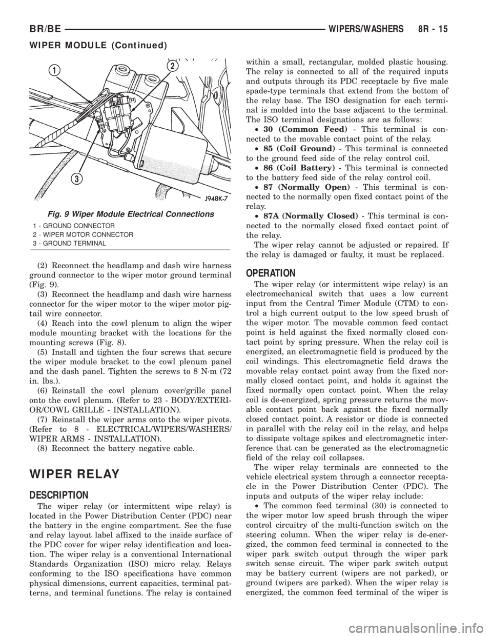
(2) Reconnect the headlamp and dash wire harness
ground connector to the wiper motor ground terminal
(Fig. 9).
(3) Reconnect the headlamp and dash wire harness
connector for the wiper motor to the wiper motor pig-
tail wire connector.
(4) Reach into the cowl plenum to align the wiper
module mounting bracket with the locations for the
mounting screws (Fig. 8).
(5) Install and tighten the four screws that secure
the wiper module bracket to the cowl plenum panel
and the dash panel. Tighten the screws to 8 N´m (72
in. lbs.).
(6) Reinstall the cowl plenum cover/grille panel
onto the cowl plenum. (Refer to 23 - BODY/EXTERI-
OR/COWL GRILLE - INSTALLATION).
(7) Reinstall the wiper arms onto the wiper pivots.
(Refer to 8 - ELECTRICAL/WIPERS/WASHERS/
WIPER ARMS - INSTALLATION).
(8) Reconnect the battery negative cable.
WIPER RELAY
DESCRIPTION
The wiper relay (or intermittent wipe relay) is
located in the Power Distribution Center (PDC) near
the battery in the engine compartment. See the fuse
and relay layout label affixed to the inside surface of
the PDC cover for wiper relay identification and loca-
tion. The wiper relay is a conventional International
Standards Organization (ISO) micro relay. Relays
conforming to the ISO specifications have common
physical dimensions, current capacities, terminal pat-
terns, and terminal functions. The relay is containedwithin a small, rectangular, molded plastic housing.
The relay is connected to all of the required inputs
and outputs through its PDC receptacle by five male
spade-type terminals that extend from the bottom of
the relay base. The ISO designation for each termi-
nal is molded into the base adjacent to the terminal.
The ISO terminal designations are as follows:
²30 (Common Feed)- This terminal is con-
nected to the movable contact point of the relay.
²85 (Coil Ground)- This terminal is connected
to the ground feed side of the relay control coil.
²86 (Coil Battery)- This terminal is connected
to the battery feed side of the relay control coil.
²87 (Normally Open)- This terminal is con-
nected to the normally open fixed contact point of the
relay.
²87A (Normally Closed)- This terminal is con-
nected to the normally closed fixed contact point of
the relay.
The wiper relay cannot be adjusted or repaired. If
the relay is damaged or faulty, it must be replaced.
OPERATION
The wiper relay (or intermittent wipe relay) is an
electromechanical switch that uses a low current
input from the Central Timer Module (CTM) to con-
trol a high current output to the low speed brush of
the wiper motor. The movable common feed contact
point is held against the fixed normally closed con-
tact point by spring pressure. When the relay coil is
energized, an electromagnetic field is produced by the
coil windings. This electromagnetic field draws the
movable relay contact point away from the fixed nor-
mally closed contact point, and holds it against the
fixed normally open contact point. When the relay
coil is de-energized, spring pressure returns the mov-
able contact point back against the fixed normally
closed contact point. A resistor or diode is connected
in parallel with the relay coil in the relay, and helps
to dissipate voltage spikes and electromagnetic inter-
ference that can be generated as the electromagnetic
field of the relay coil collapses.
The wiper relay terminals are connected to the
vehicle electrical system through a connector recepta-
cle in the Power Distribution Center (PDC). The
inputs and outputs of the wiper relay include:
²The common feed terminal (30) is connected to
the wiper motor low speed brush through the wiper
control circuitry of the multi-function switch on the
steering column. When the wiper relay is de-ener-
gized, the common feed terminal is connected to the
wiper park switch output through the wiper park
switch sense circuit. The wiper park switch output
may be battery current (wipers are not parked), or
ground (wipers are parked). When the wiper relay is
energized, the common feed terminal of the wiper is
Fig. 9 Wiper Module Electrical Connections
1 - GROUND CONNECTOR
2 - WIPER MOTOR CONNECTOR
3 - GROUND TERMINAL
BR/BEWIPERS/WASHERS 8R - 15
WIPER MODULE (Continued)
Page 659 of 2255

connected to battery current from a fuse in the Junc-
tion Block (JB) through a fused ignition switch out-
put (run-acc) circuit.
²The coil ground terminal (85) is connected to the
relay control output of the CTM through the wiper
motor relay control circuit. The CTM controls the
ground path for this circuit internally to energize or
de-energize the wiper relay based upon its program-
ming and inputs from the wiper and washer control
circuitry of the multi-function switch and from the
wiper motor park switch.
²The coil battery terminal (86) is connected to
battery current from a fuse in the Junction Block
(JB) through a fused ignition switch output (run-acc)
circuit whenever the ignition switch is in the On or
Accessory positions.
²The normally open terminal (87) is connected to
battery current from a fuse in the Junction Block
(JB) through a fused ignition switch output (run-acc)
circuit whenever the wiper relay control coil is ener-
gized by the CTM. This circuit provides fused igni-
tion switch output (run-acc) current to the wiper
motor low speed brush only when the wiper relay
control coil is energized.
²The normally closed terminal (87A) is connected
to the output of the wiper motor park switch through
the wiper motor park switch sense circuit. This cir-
cuit provides battery current (wipers are not parked)
or ground (wipers are parked) to the wiper motor low
speed brush whenever the wiper relay control coil is
de-energized and the Off position of the wiper control
of the multi-function switch is selected.
The wiper relay can be diagnosed using conven-
tional diagnostic tools and methods.
DIAGNOSIS AND TESTING - WIPER RELAY
The wiper relay (or intermittent wipe relay) (Fig.
10) is located in the Power Distribution Center (PDC)
in the engine compartment. See the fuse and relay
layout label affixed to the inside surface of the PDC
cover for wiper relay identification and location.
Refer to the appropriate wiring information. The wir-
ing information includes wiring diagrams, proper
wire and connector repair procedures, details of wire
harness routing and retention, connector pin-out
information and location views for the various wire
harness connectors, splices and grounds.
(1) Remove the wiper relay from the PDC. (Refer
to 8 - ELECTRICAL/WIPERS/WASHERS/WIPER
RELAY - REMOVAL).
(2) A relay in the de-energized position should
have continuity between terminals 87A and 30, and
no continuity between terminals 87 and 30. If OK, go
to Step 3. If not OK, replace the faulty relay.(3) Resistance between terminals 85 and 86 (elec-
tromagnet) should be 75 5 ohms. If OK, go to Step
4. If not OK, replace the faulty relay.
(4) Connect a battery to terminals 85 and 86.
There should now be continuity between terminals
30 and 87, and no continuity between terminals 87A
and 30. If OK, test the relay input and output cir-
cuits. Refer to RELAY CIRCUIT TEST . If not OK,
replace the faulty relay.
RELAY CIRCUIT TEST
(1) The relay common feed terminal cavity (30) is
connected to the multi-function switch. There should
be continuity between the receptacle for terminal 30
of the wiper relay in the PDC and both driver low
speed wiper motor driver circuit cavities of the
instrument panel wire harness connector for the
multi-function switch at all times. If OK, go to Step
2. If not OK, repair the open driver low speed wiper
motor driver circuit(s) between the PDC and the
multi-function switch as required.
(2) The relay normally closed terminal (87A) is
connected to the wiper motor park switch through
the wiper motor park switch sense circuit. There
should be continuity between the receptacle for ter-
minal 87A of the wiper relay in the PDC and the
wiper motor park switch sense circuit cavity of the
headlamp and dash wire harness connector for the
wiper motor at all times. If OK, go to Step 3. If not
OK, repair the open wiper motor park switch sense
circuit between the PDC and the wiper motor as
required.
(3) The relay normally open terminal (87) is con-
nected to a fused ignition switch output (run-acc)
fuse in the Junction Block (JB) through a fused igni-
tion switch output (run-acc) circuit. There should be
battery voltage at the receptacle for terminal 87 of
Fig. 10 Wiper Relay
30 - COMMON FEED
85 - COIL GROUND
86 - COIL BATTERY
87 - NORMALLY OPEN
87A - NORMALLY CLOSED
8R - 16 WIPERS/WASHERSBR/BE
WIPER RELAY (Continued)
Page 660 of 2255
the wiper relay in the PDC whenever the ignition
switch is in the On or Accessory positions. If OK, go
to Step 4. If not OK, repair the open fused ignition
switch output (run-acc) circuit between the PDC and
the JB as required.
(4) The coil battery terminal (86) is connected to a
fused ignition switch output (run-acc) fuse in the JB
through a fused ignition switch output (run-acc) cir-
cuit. There should be battery voltage at the recepta-
cle for terminal 86 of the wiper relay in the PDC
whenever the ignition switch is in the On or Acces-
sory positions. If OK, go to Step 5. If not OK, repair
the open fused ignition switch output (run-acc) cir-
cuit between the PDC and the JB as required.
(5) The coil ground terminal (85) is connected to
the output of the Central Timer Module (CTM)
through the wiper motor relay control circuit. There
should be continuity between the receptacle for ter-
minal 85 of the wiper relay in the PDC and the wiper
motor relay control circuit cavity of the instrument
panel wire harness connector (Connector C1) for the
CTM at all times. If not OK, repair the open wiper
motor relay control circuit between the PDC and the
CTM as required.
REMOVAL
(1) Disconnect and isolate the battery negative
cable.
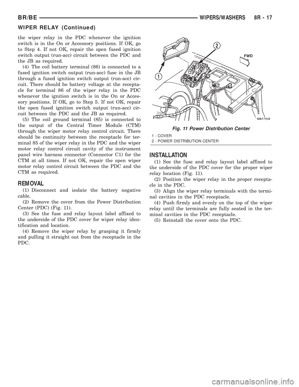
(2) Remove the cover from the Power Distribution
Center (PDC) (Fig. 11).
(3) See the fuse and relay layout label affixed to
the underside of the PDC cover for wiper relay iden-
tification and location.
(4) Remove the wiper relay by grasping it firmly
and pulling it straight out from the receptacle in the
PDC.
INSTALLATION
(1) See the fuse and relay layout label affixed to
the underside of the PDC cover for the proper wiper
relay location (Fig. 11).
(2) Position the wiper relay in the proper recepta-
cle in the PDC.
(3) Align the wiper relay terminals with the termi-
nal cavities in the PDC receptacle.
(4) Push firmly and evenly on the top of the wiper
relay until the terminals are fully seated in the ter-
minal cavities in the PDC receptacle.
(5) Reinstall the cover onto the PDC.
Fig. 11 Power Distribution Center
1 - COVER
2 - POWER DISTRIBUTION CENTER
BR/BEWIPERS/WASHERS 8R - 17
WIPER RELAY (Continued)
Page 667 of 2255

SYMBOLS
International symbols are used throughout the wir-
ing diagrams. These symbols are consistent with
those being used around the world (Fig. 3).
TERMINOLOGY
This is a list of terms and definitions used in the
wiring diagrams.
LHD .................Left Hand Drive Vehicles
RHD................Right Hand Drive Vehicles
ATX . . Automatic Transmissions-Front Wheel Drive
MTX....Manual Transmissions-Front Wheel Drive
AT ....Automatic Transmissions-Rear Wheel Drive
MT .....Manual Transmissions-Rear Wheel Drive
SOHC...........Single Over Head Cam Engine
DOHC..........Double Over Head Cam Engine
Built-Up-Export........ Vehicles Built For Sale In
Markets Other Than North America
Except-Built-Up-Export . . Vehicles Built For Sale In
North America
DESCRIPTION - CIRCUIT INFORMATION
Each wire shown in the diagrams contains a code
which identifies the main circuit, part of the main
circuit, gage of wire, and color (Fig. 4).
WIRE COLOR CODE CHART
COLOR CODE COLOR
BL BLUE
BK BLACK
BR BROWN
DB DARK BLUE
DG DARK GREEN
GY GRAY
LB LIGHT BLUE
LG LIGHT GREEN
OR ORANGE
PK PINK
RD RED
TN TAN
VT VIOLET
WT WHITE
YL YELLOW
* WITH TRACER
DESCRIPTION - CIRCUIT FUNCTIONS
All circuits in the diagrams use an alpha/numeric
code to identify the wire and it's function. To identify
which circuit code applies to a system, refer to the
Circuit Identification Code Chart. This chart shows
the main circuits only and does not show the second-
ary codes that may apply to some models.
CIRCUIT IDENTIFICATION CODE CHART
CIRCUIT FUNCTION
A BATTERY FEED
B BRAKE CONTROLS
C CLIMATE CONTROLS
D DIAGNOSTIC CIRCUITS
E DIMMING ILLUMINATION
CIRCUITS
F FUSED CIRCUITS
G MONITORING CIRCUITS
(GAUGES)
H OPEN
I NOT USED
J OPEN
K POWERTRAIN CONTROL
MODULE
L EXTERIOR LIGHTING
M INTERIOR LIGHTING
N NOT USED
O NOT USED
P POWER OPTION (BATTERY
FEED)
Q POWER OPTIONS (IGNITION
FEED)
R PASSIVE RESTRAINT
S SUSPENSION/STEERING
T TRANSMISSION/TRANSAXLE/
TRANSFER CASE
U OPEN
V SPEED CONTROL, WIPER/
WASHER
W OPEN
X AUDIO SYSTEMS
Y OPEN
Z GROUNDS
8W - 01 - 4 8W-01 WIRING DIAGRAM INFORMATIONBR/BE
WIRING DIAGRAM INFORMATION (Continued)
Page 670 of 2255
WARNINGS - GENERAL
WARNINGSprovide information to prevent per-
sonal injury and vehicle damage. Below is a list of
general warnings that should be followed any time a
vehicle is being serviced.
WARNING:: ALWAYS WEAR SAFETY GLASSES FOR
EYE PROTECTION.
WARNING: USE SAFETY STANDS ANYTIME A PRO-
CEDURE REQUIRES BEING UNDER A VEHICLE.
WARNING: BE SURE THAT THE IGNITION SWITCH
ALWAYS IS IN THE OFF POSITION, UNLESS THE
PROCEDURE REQUIRES IT TO BE ON.
WARNING: SET THE PARKING BRAKE WHEN
WORKING ON ANY VEHICLE. AN AUTOMATIC
TRANSMISSION SHOULD BE IN PARK. A MANUAL
TRANSMISSION SHOULD BE IN NEUTRAL.
WARNING: OPERATE THE ENGINE ONLY IN A
WELL-VENTILATED AREA.
WARNING: KEEP AWAY FROM MOVING PARTS
WHEN THE ENGINE IS RUNNING, ESPECIALLY THE
FAN AND BELTS.
WARNING: TO PREVENT SERIOUS BURNS, AVOID
CONTACT WITH HOT PARTS SUCH AS THE RADIA-
TOR, EXHAUST MANIFOLD(S), TAIL PIPE, CATA-
LYTIC CONVERTER AND MUFFLER.
WARNING: DO NOT ALLOW FLAME OR SPARKS
NEAR THE BATTERY. GASES ARE ALWAYS
PRESENT IN AND AROUND THE BATTERY.
WARNING: ALWAYS REMOVE RINGS, WATCHES,
LOOSE HANGING JEWELRY AND AVOID LOOSE
CLOTHING.
DIAGNOSIS AND TESTING - WIRING HARNESS
TROUBLESHOOTING TOOLS
When diagnosing a problem in an electrical circuit
there are several common tools necessary. These tools
are listed and explained below.
²Jumper Wire - This is a test wire used to con-
nect two points of a circuit. It can be used to bypass
an open in a circuit.WARNING: NEVER USE A JUMPER WIRE ACROSS
A LOAD, SUCH AS A MOTOR, CONNECTED
BETWEEN A BATTERY FEED AND GROUND.
²Voltmeter - Used to check for voltage on a cir-
cuit. Always connect the black lead to a known good
ground and the red lead to the positive side of the
circuit.
CAUTION: Most of the electrical components used
in today's vehicles are Solid State. When checking
voltages in these circuits, use a meter with a 10 -
megohm or greater impedance rating.
²Ohmmeter - Used to check the resistance
between two points of a circuit. Low or no resistance
in a circuit means good continuity.
CAUTION: Most of the electrical components used
in today's vehicles are Solid State. When checking
resistance in these circuits use a meter with a 10 -
megohm or greater impedance rating. In addition,
make sure the power is disconnected from the cir-
cuit. Circuits that are powered up by the vehicle's
electrical system can cause damage to the equip-
ment and provide false readings.
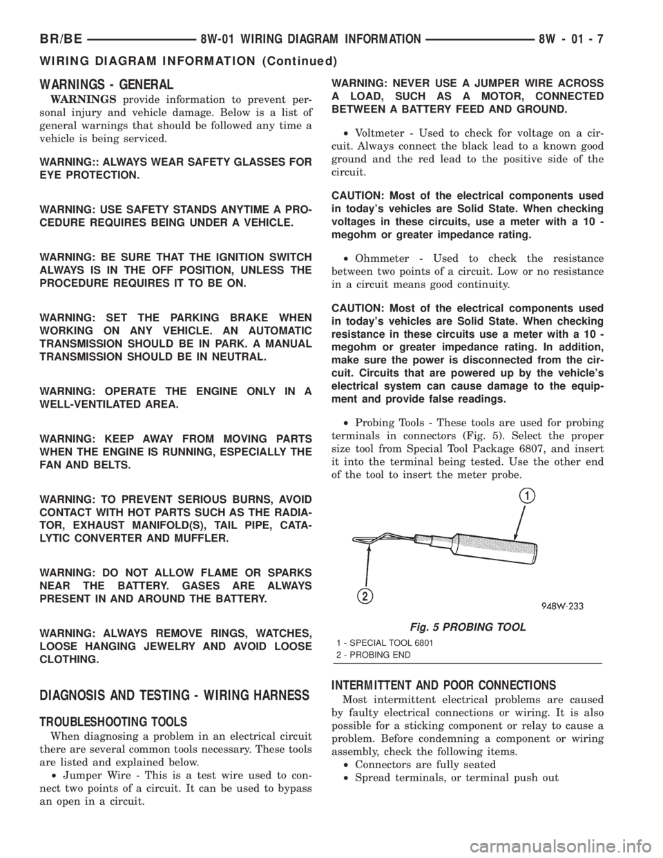
²Probing Tools - These tools are used for probing
terminals in connectors (Fig. 5). Select the proper
size tool from Special Tool Package 6807, and insert
it into the terminal being tested. Use the other end
of the tool to insert the meter probe.
INTERMITTENT AND POOR CONNECTIONS
Most intermittent electrical problems are caused
by faulty electrical connections or wiring. It is also
possible for a sticking component or relay to cause a
problem. Before condemning a component or wiring
assembly, check the following items.
²Connectors are fully seated
²Spread terminals, or terminal push out
Fig. 5 PROBING TOOL
1 - SPECIAL TOOL 6801
2 - PROBING END
BR/BE8W-01 WIRING DIAGRAM INFORMATION 8W - 01 - 7
WIRING DIAGRAM INFORMATION (Continued)
Page 672 of 2255
STANDARD PROCEDURE - TESTING FOR
CONTINUITY
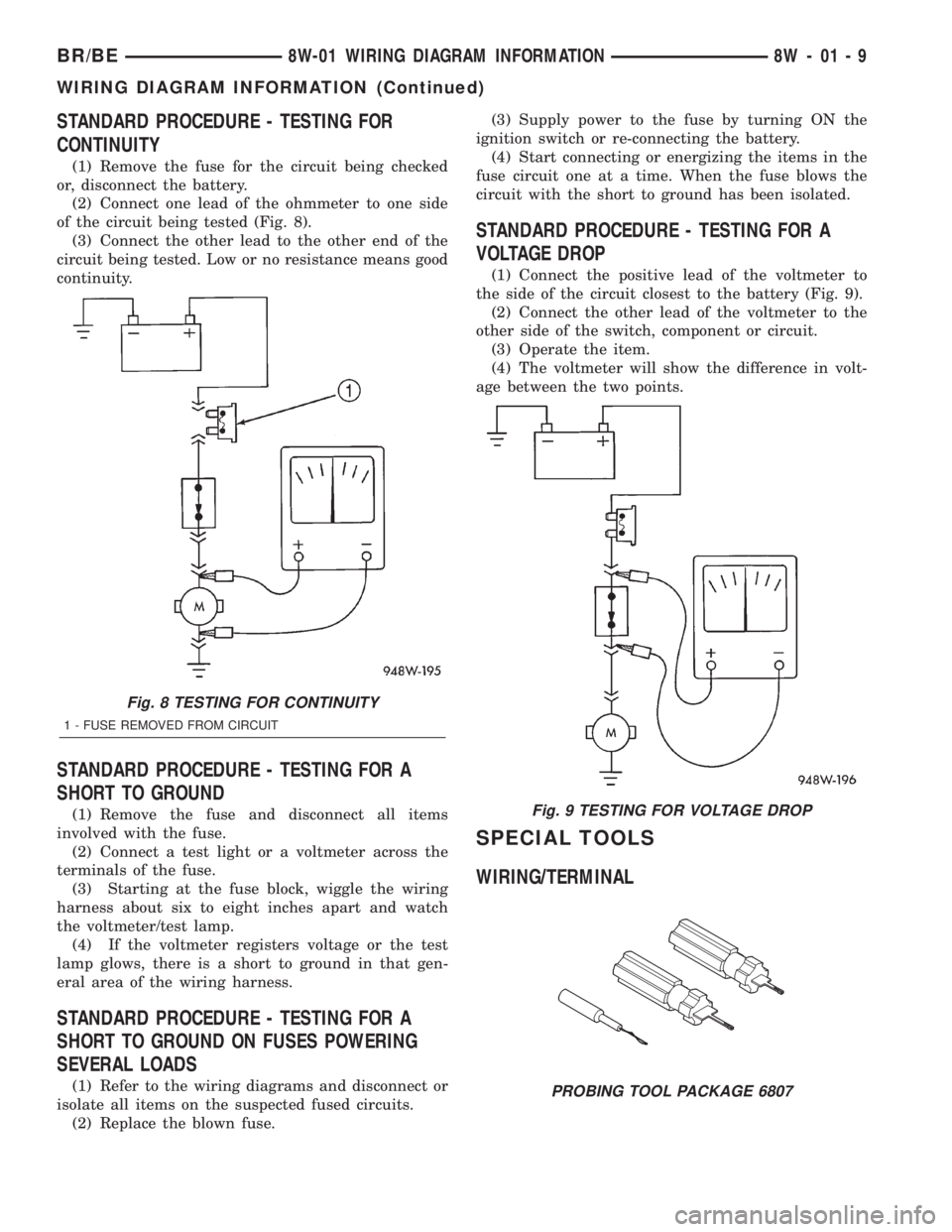
(1) Remove the fuse for the circuit being checked
or, disconnect the battery.
(2) Connect one lead of the ohmmeter to one side
of the circuit being tested (Fig. 8).
(3) Connect the other lead to the other end of the
circuit being tested. Low or no resistance means good
continuity.
STANDARD PROCEDURE - TESTING FOR A
SHORT TO GROUND
(1) Remove the fuse and disconnect all items
involved with the fuse.
(2) Connect a test light or a voltmeter across the
terminals of the fuse.
(3) Starting at the fuse block, wiggle the wiring
harness about six to eight inches apart and watch
the voltmeter/test lamp.
(4) If the voltmeter registers voltage or the test
lamp glows, there is a short to ground in that gen-
eral area of the wiring harness.
STANDARD PROCEDURE - TESTING FOR A
SHORT TO GROUND ON FUSES POWERING
SEVERAL LOADS
(1) Refer to the wiring diagrams and disconnect or
isolate all items on the suspected fused circuits.
(2) Replace the blown fuse.(3) Supply power to the fuse by turning ON the
ignition switch or re-connecting the battery.
(4) Start connecting or energizing the items in the
fuse circuit one at a time. When the fuse blows the
circuit with the short to ground has been isolated.
STANDARD PROCEDURE - TESTING FOR A
VOLTAGE DROP
(1) Connect the positive lead of the voltmeter to
the side of the circuit closest to the battery (Fig. 9).
(2) Connect the other lead of the voltmeter to the
other side of the switch, component or circuit.
(3) Operate the item.
(4) The voltmeter will show the difference in volt-
age between the two points.
SPECIAL TOOLS
WIRING/TERMINAL
Fig. 8 TESTING FOR CONTINUITY
1 - FUSE REMOVED FROM CIRCUIT
Fig. 9 TESTING FOR VOLTAGE DROP
PROBING TOOL PACKAGE 6807
BR/BE8W-01 WIRING DIAGRAM INFORMATION 8W - 01 - 9
WIRING DIAGRAM INFORMATION (Continued)
Page 673 of 2255
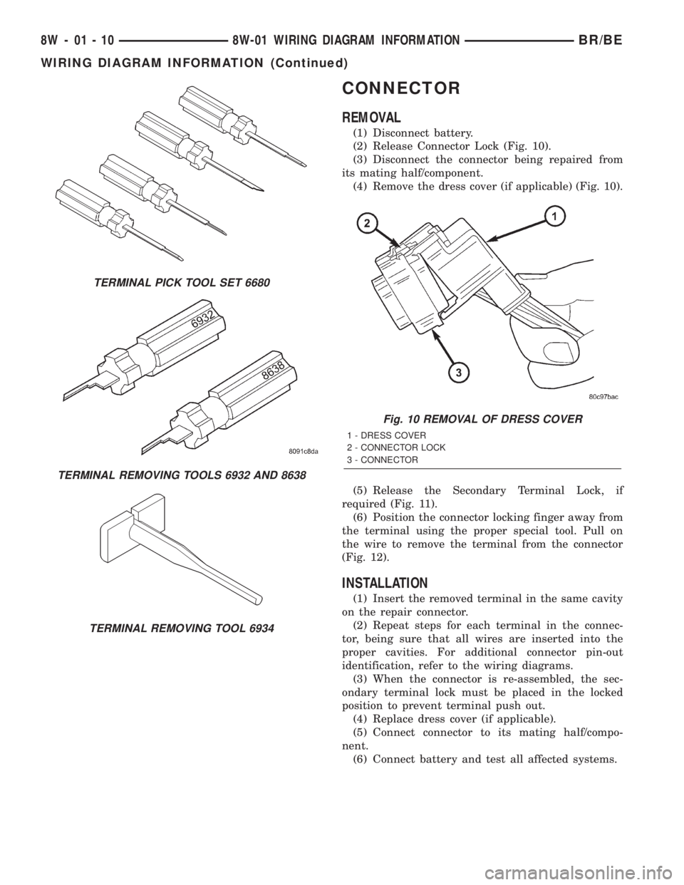
CONNECTOR
REMOVAL
(1) Disconnect battery.
(2) Release Connector Lock (Fig. 10).
(3) Disconnect the connector being repaired from
its mating half/component.
(4) Remove the dress cover (if applicable) (Fig. 10).
(5) Release the Secondary Terminal Lock, if
required (Fig. 11).
(6) Position the connector locking finger away from
the terminal using the proper special tool. Pull on
the wire to remove the terminal from the connector
(Fig. 12).
INSTALLATION
(1) Insert the removed terminal in the same cavity
on the repair connector.
(2) Repeat steps for each terminal in the connec-
tor, being sure that all wires are inserted into the
proper cavities. For additional connector pin-out
identification, refer to the wiring diagrams.
(3) When the connector is re-assembled, the sec-
ondary terminal lock must be placed in the locked
position to prevent terminal push out.
(4) Replace dress cover (if applicable).
(5) Connect connector to its mating half/compo-
nent.
(6) Connect battery and test all affected systems.
TERMINAL PICK TOOL SET 6680
TERMINAL REMOVING TOOLS 6932 AND 8638
TERMINAL REMOVING TOOL 6934
Fig. 10 REMOVAL OF DRESS COVER
1 - DRESS COVER
2 - CONNECTOR LOCK
3 - CONNECTOR
8W - 01 - 10 8W-01 WIRING DIAGRAM INFORMATIONBR/BE
WIRING DIAGRAM INFORMATION (Continued)
Page 676 of 2255
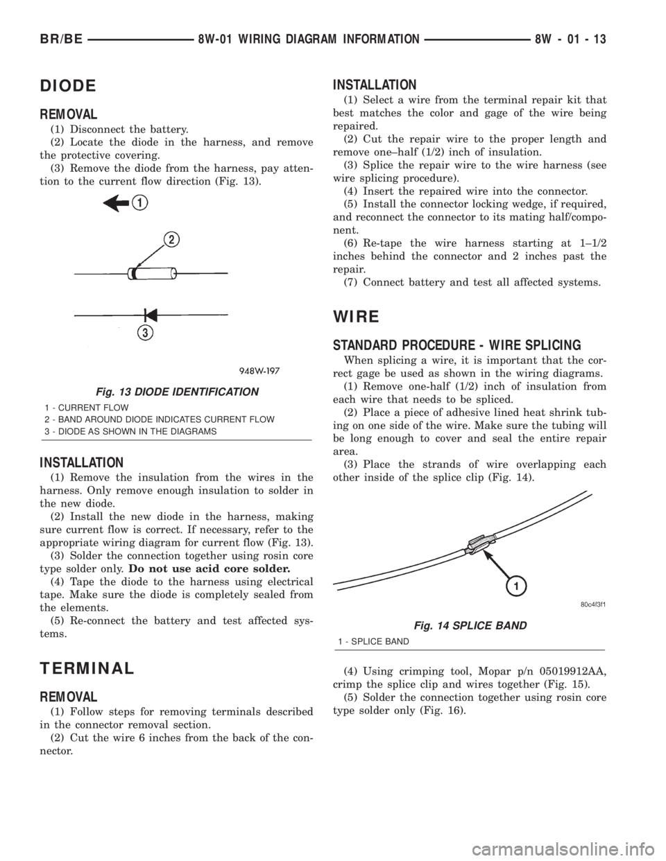
DIODE
REMOVAL
(1) Disconnect the battery.
(2) Locate the diode in the harness, and remove
the protective covering.
(3) Remove the diode from the harness, pay atten-
tion to the current flow direction (Fig. 13).
INSTALLATION
(1) Remove the insulation from the wires in the
harness. Only remove enough insulation to solder in
the new diode.
(2) Install the new diode in the harness, making
sure current flow is correct. If necessary, refer to the
appropriate wiring diagram for current flow (Fig. 13).
(3) Solder the connection together using rosin core
type solder only.Do not use acid core solder.
(4) Tape the diode to the harness using electrical
tape. Make sure the diode is completely sealed from
the elements.
(5) Re-connect the battery and test affected sys-
tems.
TERMINAL
REMOVAL
(1) Follow steps for removing terminals described
in the connector removal section.
(2) Cut the wire 6 inches from the back of the con-
nector.
INSTALLATION
(1) Select a wire from the terminal repair kit that
best matches the color and gage of the wire being
repaired.
(2) Cut the repair wire to the proper length and
remove one±half (1/2) inch of insulation.
(3) Splice the repair wire to the wire harness (see
wire splicing procedure).
(4) Insert the repaired wire into the connector.
(5) Install the connector locking wedge, if required,
and reconnect the connector to its mating half/compo-
nent.
(6) Re-tape the wire harness starting at 1±1/2
inches behind the connector and 2 inches past the
repair.
(7) Connect battery and test all affected systems.
WIRE
STANDARD PROCEDURE - WIRE SPLICING
When splicing a wire, it is important that the cor-
rect gage be used as shown in the wiring diagrams.
(1) Remove one-half (1/2) inch of insulation from
each wire that needs to be spliced.
(2) Place a piece of adhesive lined heat shrink tub-
ing on one side of the wire. Make sure the tubing will
be long enough to cover and seal the entire repair
area.
(3) Place the strands of wire overlapping each
other inside of the splice clip (Fig. 14).
(4) Using crimping tool, Mopar p/n 05019912AA,
crimp the splice clip and wires together (Fig. 15).
(5) Solder the connection together using rosin core
type solder only (Fig. 16).
Fig. 13 DIODE IDENTIFICATION
1 - CURRENT FLOW
2 - BAND AROUND DIODE INDICATES CURRENT FLOW
3 - DIODE AS SHOWN IN THE DIAGRAMS
Fig. 14 SPLICE BAND
1 - SPLICE BAND
BR/BE8W-01 WIRING DIAGRAM INFORMATION 8W - 01 - 13