2002 DODGE RAM battery
[x] Cancel search: batteryPage 1007 of 2255
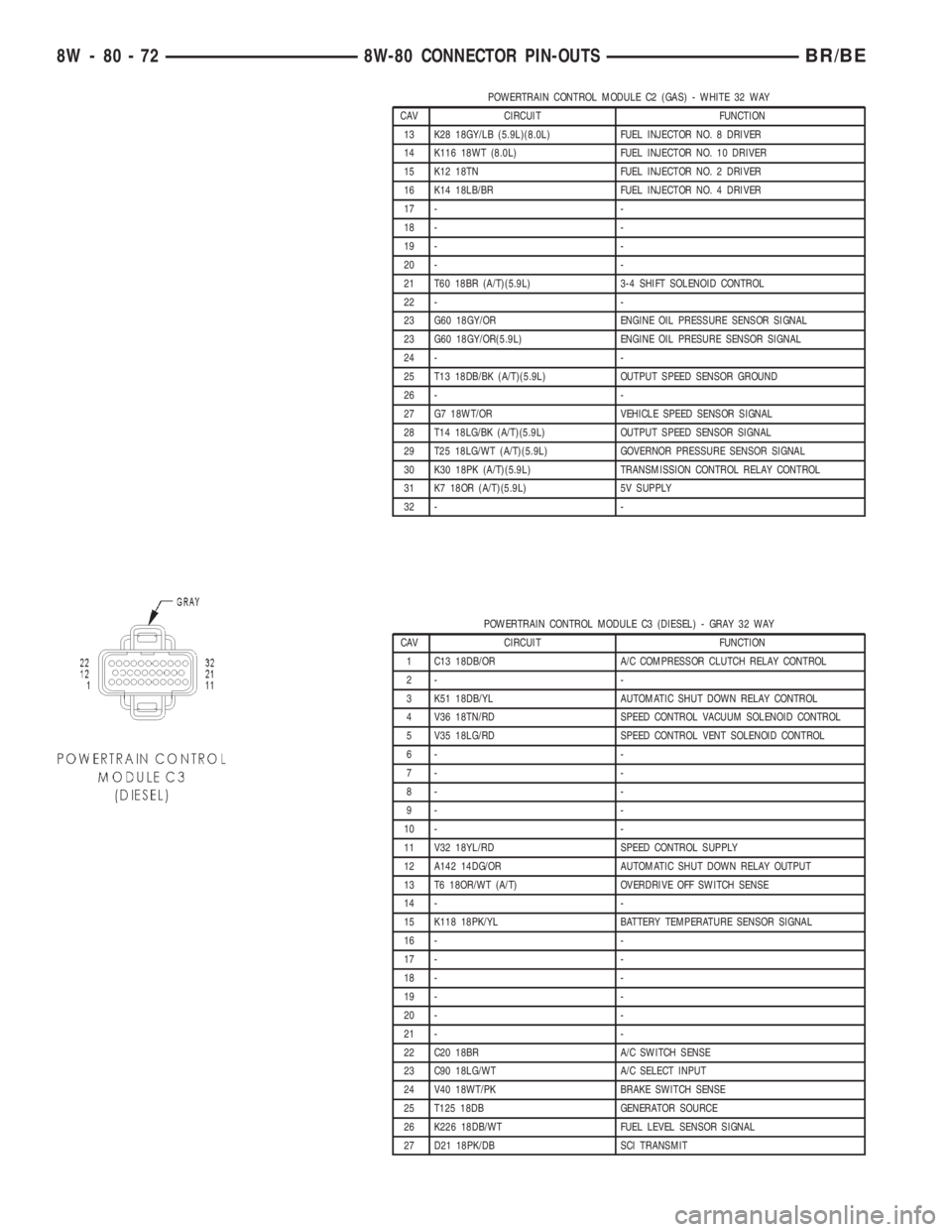
POWERTRAIN CONTROL MODULE C2 (GAS) - WHITE 32 WAY
CAV CIRCUIT FUNCTION
13 K28 18GY/LB (5.9L)(8.0L) FUEL INJECTOR NO. 8 DRIVER
14 K116 18WT (8.0L) FUEL INJECTOR NO. 10 DRIVER
15 K12 18TN FUEL INJECTOR NO. 2 DRIVER
16 K14 18LB/BR FUEL INJECTOR NO. 4 DRIVER
17 - -
18 - -
19 - -
20 - -
21 T60 18BR (A/T)(5.9L) 3-4 SHIFT SOLENOID CONTROL
22 - -
23 G60 18GY/OR ENGINE OIL PRESSURE SENSOR SIGNAL
23 G60 18GY/OR(5.9L) ENGINE OIL PRESURE SENSOR SIGNAL
24 - -
25 T13 18DB/BK (A/T)(5.9L) OUTPUT SPEED SENSOR GROUND
26 - -
27 G7 18WT/OR VEHICLE SPEED SENSOR SIGNAL
28 T14 18LG/BK (A/T)(5.9L) OUTPUT SPEED SENSOR SIGNAL
29 T25 18LG/WT (A/T)(5.9L) GOVERNOR PRESSURE SENSOR SIGNAL
30 K30 18PK (A/T)(5.9L) TRANSMISSION CONTROL RELAY CONTROL
31 K7 18OR (A/T)(5.9L) 5V SUPPLY
32 - -
POWERTRAIN CONTROL MODULE C3 (DIESEL) - GRAY 32 WAY
CAV CIRCUIT FUNCTION
1 C13 18DB/OR A/C COMPRESSOR CLUTCH RELAY CONTROL
2- -
3 K51 18DB/YL AUTOMATIC SHUT DOWN RELAY CONTROL
4 V36 18TN/RD SPEED CONTROL VACUUM SOLENOID CONTROL
5 V35 18LG/RD SPEED CONTROL VENT SOLENOID CONTROL
6- -
7- -
8- -
9- -
10 - -
11 V32 18YL/RD SPEED CONTROL SUPPLY
12 A142 14DG/OR AUTOMATIC SHUT DOWN RELAY OUTPUT
13 T6 18OR/WT (A/T) OVERDRIVE OFF SWITCH SENSE
14 - -
15 K118 18PK/YL BATTERY TEMPERATURE SENSOR SIGNAL
16 - -
17 - -
18 - -
19 - -
20 - -
21 - -
22 C20 18BR A/C SWITCH SENSE
23 C90 18LG/WT A/C SELECT INPUT
24 V40 18WT/PK BRAKE SWITCH SENSE
25 T125 18DB GENERATOR SOURCE
26 K226 18DB/WT FUEL LEVEL SENSOR SIGNAL
27 D21 18PK/DB SCI TRANSMIT
8W - 80 - 72 8W-80 CONNECTOR PIN-OUTSBR/BE
Page 1008 of 2255
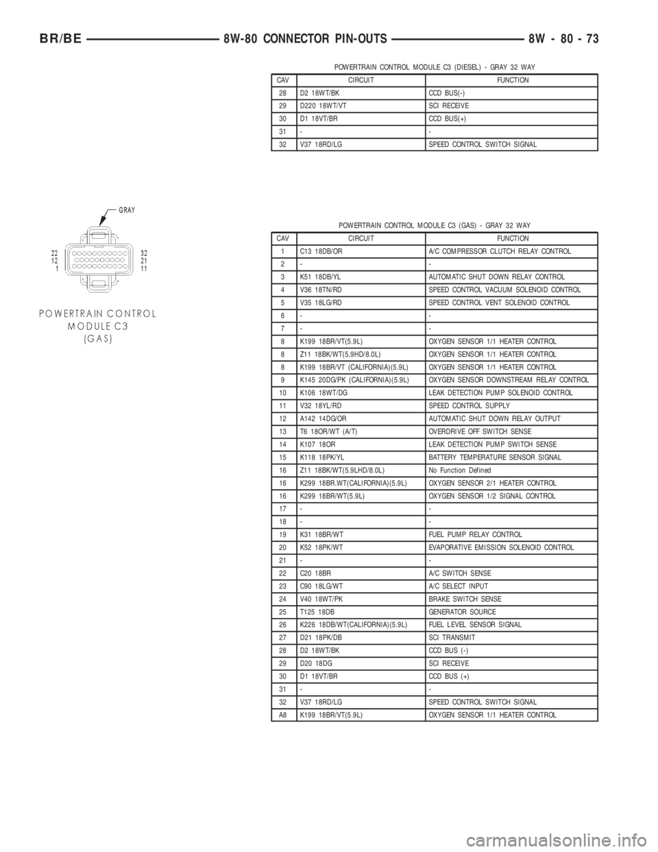
POWERTRAIN CONTROL MODULE C3 (DIESEL) - GRAY 32 WAY
CAV CIRCUIT FUNCTION
28 D2 18WT/BK CCD BUS(-)
29 D220 18WT/VT SCI RECEIVE
30 D1 18VT/BR CCD BUS(+)
31 - -
32 V37 18RD/LG SPEED CONTROL SWITCH SIGNAL
POWERTRAIN CONTROL MODULE C3 (GAS) - GRAY 32 WAY
CAV CIRCUIT FUNCTION
1 C13 18DB/OR A/C COMPRESSOR CLUTCH RELAY CONTROL
2- -
3 K51 18DB/YL AUTOMATIC SHUT DOWN RELAY CONTROL
4 V36 18TN/RD SPEED CONTROL VACUUM SOLENOID CONTROL
5 V35 18LG/RD SPEED CONTROL VENT SOLENOID CONTROL
6- -
7- -
8 K199 18BR/VT(5.9L) OXYGEN SENSOR 1/1 HEATER CONTROL
8 Z11 18BK/WT(5.9HD/8.0L) OXYGEN SENSOR 1/1 HEATER CONTROL
8 K199 18BR/VT (CALIFORNIA)(5.9L) OXYGEN SENSOR 1/1 HEATER CONTROL
9 K145 20DG/PK (CALIFORNIA)(5.9L) OXYGEN SENSOR DOWNSTREAM RELAY CONTROL
10 K106 18WT/DG LEAK DETECTION PUMP SOLENOID CONTROL
11 V32 18YL/RD SPEED CONTROL SUPPLY
12 A142 14DG/OR AUTOMATIC SHUT DOWN RELAY OUTPUT
13 T6 18OR/WT (A/T) OVERDRIVE OFF SWITCH SENSE
14 K107 18OR LEAK DETECTION PUMP SWITCH SENSE
15 K118 18PK/YL BATTERY TEMPERATURE SENSOR SIGNAL
16 Z11 18BK/WT(5.9LHD/8.0L) No Function Defined
16 K299 18BR.WT(CALIFORNIA)(5.9L) OXYGEN SENSOR 2/1 HEATER CONTROL
16 K299 18BR/WT(5.9L) OXYGEN SENSOR 1/2 SIGNAL CONTROL
17 - -
18 - -
19 K31 18BR/WT FUEL PUMP RELAY CONTROL
20 K52 18PK/WT EVAPORATIVE EMISSION SOLENOID CONTROL
21 - -
22 C20 18BR A/C SWITCH SENSE
23 C90 18LG/WT A/C SELECT INPUT
24 V40 18WT/PK BRAKE SWITCH SENSE
25 T125 18DB GENERATOR SOURCE
26 K226 18DB/WT(CALIFORNIA)(5.9L) FUEL LEVEL SENSOR SIGNAL
27 D21 18PK/DB SCI TRANSMIT
28 D2 18WT/BK CCD BUS (-)
29 D20 18DG SCI RECEIVE
30 D1 18VT/BR CCD BUS (+)
31 - -
32 V37 18RD/LG SPEED CONTROL SWITCH SIGNAL
A8 K199 18BR/VT(5.9L) OXYGEN SENSOR 1/1 HEATER CONTROL
BR/BE8W-80 CONNECTOR PIN-OUTS 8W - 80 - 73
Page 1018 of 2255
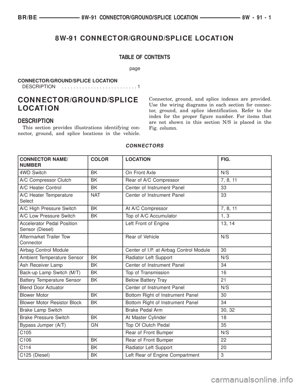
8W-91 CONNECTOR/GROUND/SPLICE LOCATION
TABLE OF CONTENTS
page
CONNECTOR/GROUND/SPLICE LOCATION
DESCRIPTION..........................1
CONNECTOR/GROUND/SPLICE
LOCATION
DESCRIPTION
This section provides illustrations identifying con-
nector, ground, and splice locations in the vehicle.Connector, ground, and splice indexes are provided.
Use the wiring diagrams in each section for connec-
tor, ground, and splice identification. Refer to the
index for the proper figure number. For items that
are not shown in this section N/S is placed in the
Fig. column.
CONNECTORS
CONNECTOR NAME/
NUMBERCOLOR LOCATION FIG.
4WD Switch BK On Front Axle N/S
A/C Compressor Clutch BK Rear of A/C Compressor 7, 8, 11
A/C Heater Control BK Center of Instrument Panel 33
A/C Heater Temperature
SelectNAT Center of Instrument Panel 33
A/C High Pressure Switch BK At A/C Compressor 7, 8, 11
A/C Low Pressure Switch BK Top of A/C Accumulator 1, 3
Accelerator Pedal Position
Sensor (Diesel)Left Front of Engine 13, 14
Aftermarket Trailer Tow
ConnectorRear of Vehicle N/S
Airbag Control Module Center of I.P. at Airbag Control Module 30
Ambient Temperature Sensor BK Radiator Left Support N/S
Ash Receiver Lamp BK Center of Instrument Panel 34
Back-up Lamp Switch (M/T) BK Top of Transmission 16
Battery Temperature Sensor BK Below Battery Tray 21
Blend Door Actuator Center of Instrument Panel N/S
Blower Motor BK Bottom Right of Instrument Panel 30
Blower Motor Resistor Block BK Bottom Right of Instrument Panel 34
Brake Lamp Switch Brake Pedal Arm 30, 32
Brake Pressure Switch BK At Master Cylinder 18
Bypass Jumper (A/T) GN Top Of Clutch Pedal 35
C105 Rear of Front Bumper N/S
C106 BK Rear of Front Bumper 22
C114 BK Radiator Left Support 20
C125 (Diesel) BK Left Rear of Engine Compartment 3
BR/BE8W-91 CONNECTOR/GROUND/SPLICE LOCATION 8W - 91 - 1
Page 1025 of 2255
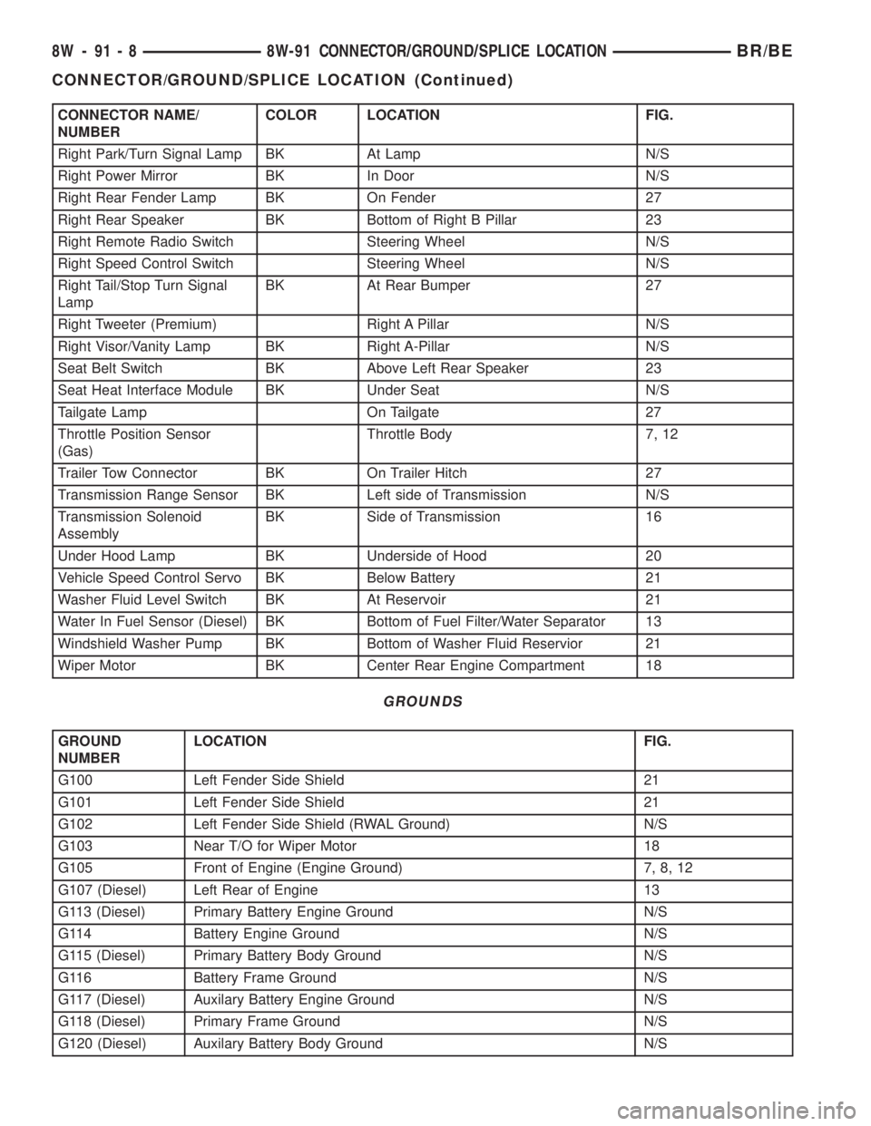
CONNECTOR NAME/
NUMBERCOLOR LOCATION FIG.
Right Park/Turn Signal Lamp BK At Lamp N/S
Right Power Mirror BK In Door N/S
Right Rear Fender Lamp BK On Fender 27
Right Rear Speaker BK Bottom of Right B Pillar 23
Right Remote Radio Switch Steering Wheel N/S
Right Speed Control Switch Steering Wheel N/S
Right Tail/Stop Turn Signal
LampBK At Rear Bumper 27
Right Tweeter (Premium) Right A Pillar N/S
Right Visor/Vanity Lamp BK Right A-Pillar N/S
Seat Belt Switch BK Above Left Rear Speaker 23
Seat Heat Interface Module BK Under Seat N/S
Tailgate Lamp On Tailgate 27
Throttle Position Sensor
(Gas)Throttle Body 7, 12
Trailer Tow Connector BK On Trailer Hitch 27
Transmission Range Sensor BK Left side of Transmission N/S
Transmission Solenoid
AssemblyBK Side of Transmission 16
Under Hood Lamp BK Underside of Hood 20
Vehicle Speed Control Servo BK Below Battery 21
Washer Fluid Level Switch BK At Reservoir 21
Water In Fuel Sensor (Diesel) BK Bottom of Fuel Filter/Water Separator 13
Windshield Washer Pump BK Bottom of Washer Fluid Reservior 21
Wiper Motor BK Center Rear Engine Compartment 18
GROUNDS
GROUND
NUMBERLOCATION FIG.
G100 Left Fender Side Shield 21
G101 Left Fender Side Shield 21
G102 Left Fender Side Shield (RWAL Ground) N/S
G103 Near T/O for Wiper Motor 18
G105 Front of Engine (Engine Ground) 7, 8, 12
G107 (Diesel) Left Rear of Engine 13
G113 (Diesel) Primary Battery Engine Ground N/S
G114 Battery Engine Ground N/S
G115 (Diesel) Primary Battery Body Ground N/S
G116 Battery Frame Ground N/S
G117 (Diesel) Auxilary Battery Engine Ground N/S
G118 (Diesel) Primary Frame Ground N/S
G120 (Diesel) Auxilary Battery Body Ground N/S
8W - 91 - 8 8W-91 CONNECTOR/GROUND/SPLICE LOCATIONBR/BE
CONNECTOR/GROUND/SPLICE LOCATION (Continued)
Page 1026 of 2255
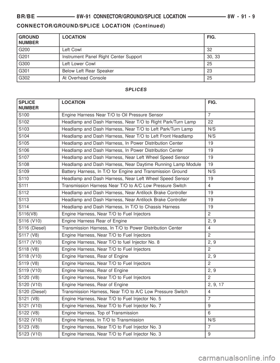
GROUND
NUMBERLOCATION FIG.
G200 Left Cowl 32
G201 Instrument Panel Right Center Support 30, 33
G300 Left Lower Cowl 25
G301 Below Left Rear Speaker 23
G302 At Overhead Console 25
SPLICES
SPLICE
NUMBERLOCATION FIG.
S100 Engine Harness Near T/O to Oil Pressure Sensor 7
S102 Headlamp and Dash Harness, Near T/O to Right Park/Turn Lamp 22
S103 Headlamp and Dash Harness, Near T/O to Left Park/Turn Lamp N/S
S104 Headlamp and Dash Harness, Near T/O to Left Front Headlamp N/S
S105 Headlamp and Dash Harness, In Power Distribution Center 19
S106 Headlamp and Dash Harness, In Power Distribution Center 19
S107 Headlamp and Dash Harness, Near Left Wheel Speed Sensor 19
S108 Headlamp and Dash Harness, Near Daytime Running Lamp Module 19
S109 Battery Harness, In T/O for Engine and Transmission Ground N/S
S110 Headlamp and Dash Harness, Near Left Wheel Speed Sensor 19
S111 Transmission Harness Near T/O to A/C Low Pressure Switch 4
S112 Headlamp and Dash Harness, Near Antilock Brake Controller 19
S113 Headlamp and Dash Harness, Near Antilock Brake Controller 19
S114 Headlamp and Dash Harness, In T/O to Chassis Harness 19
S116(V8) Engine Harness, Near T/O to Fuel Injectors 2
S116 (V10) Engine Harness Rear of Engine 2, 9
S116 (Diesel) Transmission Harness, In T/O to Power Distribution Center 4
S117 (V8) Engine Harness, Near T/O to Fuel Injectors 2
S117 (V10) Engine Harness, Near T/O to fuel Injector No. 8 2, 9
S118 (V8) Engine Harness, Near T/O to Fuel Injectors 2
S118 (V10) Engine Harness, Rear of Engine 2, 9
S119 (V8) Engine Harness, Near T/O to Fuel Injectors 2
S119 (V10) Engine Harness, Rear of Engine 2, 9
S120 (V8) Engine Harness, Near T/O to Fuel Injectors 2
S120 (V10) Engine Harness, Rear of Engine 2, 9, 17
S120 (Diesel) Transmission Harness, Near T/O to A/C Low Pressure Switch 4
S121 (V8) Engine Harness, Near T/O to Fuel Injector No. 5 7
S121 (V10) Engine Harness, Near T/O to Fuel Injector No. 7 9
S122 (V8) Engine Harness, Top of Transmission 6
S122 (V10) Engine Harness, In T/O to Transmission N/S
S123 (V8) Engine Harness, Near T/O to Fuel Injector No. 3 7
S123 (V10) Engine Harness, Near T/O to Fuel Injector No. 3 9
BR/BE8W-91 CONNECTOR/GROUND/SPLICE LOCATION 8W - 91 - 9
CONNECTOR/GROUND/SPLICE LOCATION (Continued)
Page 1061 of 2255
tribution points for the electrical current required to
operate all of the many standard and optional facto-
ry-installed electrical and electronic powertrain,
chassis, safety, security, comfort and convenience sys-
tems. At the same time, the power distribution sys-
tem was designed to provide ready access to these
electrical distribution points for the vehicle techni-
cian to use when conducting diagnosis and repair of
faulty circuits. The power distribution system can
also prove useful for the sourcing of additional elec-
trical circuits that may be required to provide the
electrical current needed to operate many accessories
that the vehicle owner may choose to have installed
in the aftermarket.
SPECIAL TOOLS
POWER DISTRIBUTION SYSTEMS
CIGAR LIGHTER OUTLET
DESCRIPTION
A cigar lighter is standard equipment on this
model. The cigar lighter is installed in the instru-
ment panel next to the ash receiver, which is located
near the center of the instrument panel, below the
radio. The cigar lighter base is secured by a snap fit
within the instrument panel.
The cigar lighter knob and heating element unit,
and the cigar lighter receptacle unit are available for
service. These components cannot be repaired and, if
faulty or damaged, they must be replaced.
OPERATION
The cigar lighter consists of two major components:
a knob and heating element unit, and the cigar
lighter base or receptacle shell. The receptacle shell
is connected to ground, and an insulated contact in
the bottom of the shell is connected to battery cur-
rent. The cigar lighter receives battery voltage from afuse in the junction block only when the ignition
switch is in the Accessory or On positions.
The knob and heating element are encased within
a spring-loaded housing, which also features a sliding
protective heat shield. When the knob and heating
element are inserted in the receptacle shell, the heat-
ing element resistor coil is grounded through its
housing to the receptacle shell. If the cigar lighter
knob is pushed inward, the heat shield slides up
toward the knob exposing the heating element, and
the heating element extends from the housing toward
the insulated contact in the bottom of the receptacle
shell.
Two small spring-clip retainers are located on
either side of the insulated contact inside the bottom
of the receptacle shell. These clips engage and hold
the heating element against the insulated contact
long enough for the resistor coil to heat up. When the
heating element is engaged with the contact, battery
current can flow through the resistor coil to ground,
causing the resistor coil to heat.
When the resistor coil becomes sufficiently heated,
excess heat radiates from the heating element caus-
ing the spring-clips to expand. Once the spring-clips
expand far enough to release the heating element,
the spring-loaded housing forces the knob and heat-
ing element to pop back outward to their relaxed
position. When the cigar lighter knob and element
are pulled out of the receptacle shell, the protective
heat shield slides downward on the housing so that
the heating element is recessed and shielded around
its circumference for safety.
DIAGNOSIS AND TESTING - CIGAR LIGHTER
OUTLET
For complete circuit diagrams, refer toCigar
Lighterin Wiring Diagrams.
WARNING: REFER TO THE PASSIVE RESTRAINT
SECTION OF THE SERVICE MANUAL BEFORE
ATTEMPTING ANY STEERING WHEEL, STEERING
COLUMN, OR INSTRUMENT PANEL COMPONENT
DIAGNOSIS OR SERVICE. FAILURE TO TAKE THE
PROPER PRECAUTIONS COULD RESULT IN ACCI-
DENTAL AIRBAG DEPLOYMENT AND POSSIBLE
PERSONAL INJURY.
(1) Check the fused ignition switch output (run/ac-
cessory) fuse in the junction block. If OK, go to Step
2. If not OK, repair the shorted circuit or component
as required and replace the faulty fuse.
(2) Turn the ignition switch to the On position.
Check for battery voltage at the fused ignition switch
output (run/accessory) fuse in the junction block. If
OK, go to Step 3. If not OK, repair the open fused
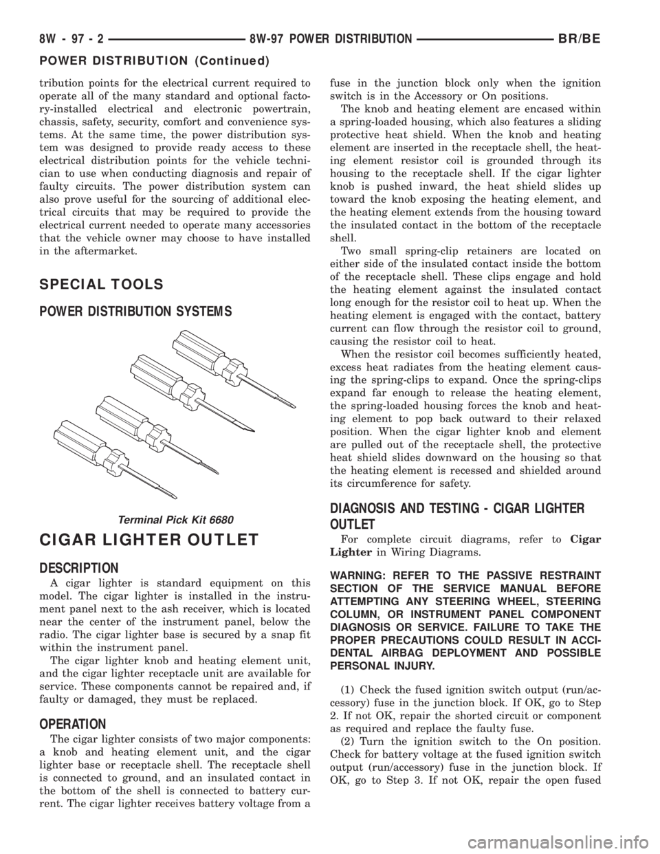
Terminal Pick Kit 6680
8W - 97 - 2 8W-97 POWER DISTRIBUTIONBR/BE
POWER DISTRIBUTION (Continued)
Page 1062 of 2255
ignition switch output (run/accessory) circuit to the
ignition switch as required.
(3) Turn the ignition switch to the Off position.
Remove the cigar lighter knob and element from the
cigar lighter receptacle. Check for continuity between
the inside circumference of the cigar lighter recepta-
cle and a good ground. There should be continuity. If
OK, go to Step 4. If not OK, go to Step 5.
(4) Turn the ignition switch to the On position.
Check for battery voltage at the insulated contact
located at the back of the cigar lighter receptacle. If
OK, replace the faulty cigar lighter knob and ele-
ment. If not OK, go to Step 5.
(5) Turn the ignition switch to the Off position.
Disconnect and isolate the battery negative cable.
Remove the cigar lighter receptacle from the instru-
ment panel and disconnect the wire harness connec-
tor. Check for continuity between the ground circuit
cavity of the cigar lighter wire harness connector and
a good ground. There should be continuity. If OK, go
to Step 6. If not OK, repair the open ground circuit to
ground as required.
(6) Connect the battery negative cable. Turn the
ignition switch to the On position. Check for battery
voltage at the fused ignition switch output (run/ac-
cessory) circuit cavity of the cigar lighter wire har-
ness connector. If OK, replace the faulty cigar lighter
receptacle. If not OK, repair the open fused ignition
switch output (run/accessory) circuit to the junction
block fuse as required.
REMOVAL
(1) Disconnect and isolate the battery negative
cable.
(2) Pull the cigar lighter knob and element out of
the cigar lighter receptacle base, or unsnap the pro-
tective cap from the power outlet receptacle base
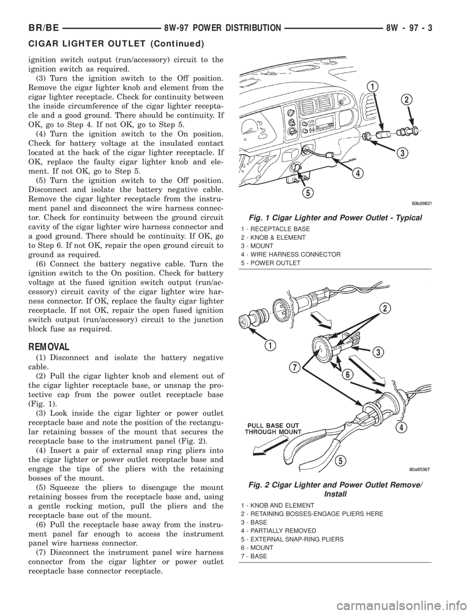
(Fig. 1).
(3) Look inside the cigar lighter or power outlet
receptacle base and note the position of the rectangu-
lar retaining bosses of the mount that secures the
receptacle base to the instrument panel (Fig. 2).
(4) Insert a pair of external snap ring pliers into
the cigar lighter or power outlet receptacle base and
engage the tips of the pliers with the retaining
bosses of the mount.
(5) Squeeze the pliers to disengage the mount
retaining bosses from the receptacle base and, using
a gentle rocking motion, pull the pliers and the
receptacle base out of the mount.
(6) Pull the receptacle base away from the instru-
ment panel far enough to access the instrument
panel wire harness connector.
(7) Disconnect the instrument panel wire harness
connector from the cigar lighter or power outlet
receptacle base connector receptacle.
Fig. 1 Cigar Lighter and Power Outlet - Typical
1 - RECEPTACLE BASE
2 - KNOB & ELEMENT
3 - MOUNT
4 - WIRE HARNESS CONNECTOR
5 - POWER OUTLET
Fig. 2 Cigar Lighter and Power Outlet Remove/
Install
1 - KNOB AND ELEMENT
2 - RETAINING BOSSES-ENGAGE PLIERS HERE
3 - BASE
4 - PARTIALLY REMOVED
5 - EXTERNAL SNAP-RING PLIERS
6 - MOUNT
7 - BASE
BR/BE8W-97 POWER DISTRIBUTION 8W - 97 - 3
CIGAR LIGHTER OUTLET (Continued)
Page 1063 of 2255
(8) Remove the cigar lighter or power outlet mount
from the instrument panel.
INSTALLATION
(1) Reconnect the instrument panel wire harness
connector to the cigar lighter or power outlet recep-
tacle base connector receptacle.
(2) Install the cigar lighter or power outlet mount
into the instrument panel.
(3) Align the splines on the outside of the cigar
lighter or power outlet receptacle base connector
receptacle with the grooves on the inside of the
mount.
(4) Press firmly on the cigar lighter or power out-
let receptacle base until the retaining bosses of the
mount are fully engaged in their receptacles.
(5) Install the cigar lighter knob and element into
the cigar lighter receptacle base, or the protective cap
into the power outlet receptacle base.
(6) Reconnect the battery negative cable.
CIRCUIT BREAKER
DESCRIPTION
Automatic resetting circuit breakers are used to
protect a system circuit from a short circuit or over-
load. Some examples of his condition can be caused
by an obstructed or stuck seat adjuster or power win-
dow motor.
The circuit breaker cannot be repaired and, if
faulty or damaged, it must be replaced.
DIAGNOSIS AND TESTING - CIRCUIT BREAKER
For circuit descriptions and diagrams, refer to Wir-
ing Diagrams.
(1) Locate the correct circuit breaker in the junc-
tion block. Pull out the circuit breaker slightly, but
be certain that the circuit breaker terminals still con-
tact the terminals in the junction block cavities.
(2) Connect the negative lead of a 12-volt DC volt-
meter to a good ground.
(3) With the voltmeter positive lead, check both
terminals of the circuit breaker for battery voltage.
If only one terminal has battery voltage, the circuit
breaker is faulty and must be replaced. If neither ter-
minal has battery voltage, repair the open circuit
from the Power Distribution Center (PDC) as
required.
GENERATOR CARTRIDGE
FUSE
DESCRIPTION
A 140 ampere generator cartridge fuse is used on
this model. The generator cartridge fuse is similar to
other cartridge fuses found in the Power Distribution
Center (PDC). This fuse has a color-coded plastic
housing and a clear plastic fuse conductor inspection
cover like other cartridge fuses, but has a higher cur-
rent rating and is connected and secured with screws
instead of being pushed onto male spade-type termi-
nals. The generator cartridge fuse cannot be repaired
and, if faulty or damaged, it must be replaced.
OPERATION
The generator cartridge fuse is secured between
the two B(+) terminal stud connection bus bars
within the Power Distribution Center (PDC). This
fuse protects the vehicle electrical system from dam-
age that could be caused by excessive charging sys-
tem output and/or excessive electrical system current
levels resulting from a faulty generator or faulty
charging system control circuits. If the current rating
of the fuse is exceeded, the fuse conductor melts to
open the generator output circuit connection to the
PDC. If a generator cartridge fuse fails, be certain to
completely inspect and test the vehicle charging sys-
tem before replacing the fuse and returning the vehi-
cle to service. Refer toCharging Systemfor the
charging system diagnostic procedures. Refer toWir-
ing Diagramsfor the location of complete PDC cir-
cuit diagrams.
REMOVAL
If a generator cartridge fuse fails, be certain to
inspect and test the vehicle charging system before
replacing the cartridge fuse and returning the vehicle
to service. Refer toCharging Systemin the index of
this service manual for the charging system diagnos-
tic procedures.
(1) Disconnect and isolate the battery negative
cable.
(2) Unlatch and remove the cover from the Power
Distribution Center (PDC).
(3) Remove the two screws that secure the genera-
tor cartridge fuse to the two B(+) terminal stud bus
bars within the PDC.
(4) Remove the generator cartridge fuse from the
PDC.
INSTALLATION
If a generator cartridge fuse fails, be certain to
inspect and test the vehicle charging system before
replacing the cartridge fuse and returning the vehicle
8W - 97 - 4 8W-97 POWER DISTRIBUTIONBR/BE
CIGAR LIGHTER OUTLET (Continued)