2002 DODGE RAM air condition
[x] Cancel search: air conditionPage 2142 of 2255
AIR CONDITIONING/PLUMBING/REFRIGERANT
OIL - DESCRIPTION)
(2) Install and tighten the high pressure cut-off
switch on the discharge line fitting. The switch
should be hand-tightened onto the discharge line fit-
ting.
(3) Plug the wire harness connector into the high
pressure cut-off switch.
(4) Connect the battery negative cable.
A/C LOW PRESSURE SWITCH
DESCRIPTION
The a/c low pressure switch is located on the top of
the accumulator. The switch is screwed onto an accu-
mulator fitting that contains a Schrader-type valve,
which allows the switch to be serviced without dis-
charging the refrigerant system. The accumulator fit-
ting is equipped with an O-ring to seal the switch
connection.
OPERATION
The a/c low pressure switch is connected in series
electrically with the a/c high pressure switch and the
a/c heater control, between ground and the Power-
train Control Module (PCM). The switch contacts
open and close causing the PCM to turn the compres-
sor clutch on and off. This regulates the refrigerant
system pressure and controls evaporator tempera-
ture. Controlling evaporator temperature prevents
condensate water on the evaporator fins from freez-
ing and obstructing air conditioning system air flow.
The a/c low pressure switch contacts are open
when the suction pressure is about 152-165 kPa
(22-24 psi) or lower. The switch contacts will close
when the suction pressure rises to about 255-296 kPa
(37-43 psi) or above. Lower ambient temperatures,
below about -1É C (30É F), will also cause the switch
contacts to open. This is due to the pressure/temper-
ature relationship of the refrigerant in the system.
The a/c low pressure switch is a factory-calibrated
unit. It cannot be adjusted or repaired and, if faulty
or damaged, it must be replaced.
DIAGNOSIS AND TESTING - A/C LOW
PRESSURE SWITCH
Before performing diagnosis of the a/c low pressure
switch, be certain that the switch is properly
installed on the accumulator fitting. If the switch is
too loose it may not open the Schrader-type valve in
the accumulator fitting, which will prevent the
switch from correctly monitoring the refrigerant sys-
tem pressure. Also verify that the refrigerant system
has the correct refrigerant charge. (Refer to 24 -HEATING & AIR CONDITIONING - DIAGNOSIS
AND TESTING - A/C PERFORMANCE)
Remember that lower ambient temperatures, below
about -1É C (30É F), during cold weather will open the
switch contacts and prevent compressor operation
due to the pressure/temperature relationship of the
refrigerant. For circuit descriptions and diagrams,
(Refer to Appropriate Wiring Information).
(1) Disconnect and isolate the battery negative
cable.
(2) Unplug the a/c low pressure switch wire har-
ness connector from the switch on the accumulator
fitting.
(3) Install a jumper wire between the two cavities
of the a/c low pressure switch wire harness connector.
(4) Connect a manifold gauge set to the refrigerant
system service ports. (Refer to 24 - HEATING & AIR
CONDITIONING/PLUMBING - STANDARD PRO-
CEDURE - REFRIGERANT SYSTEM SERVICE
EQUIPMENT)
(5) Connect the battery negative cable.
(6) Place the a/c heater mode control switch knob
in any A/C position and start the engine.
(7) Check for continuity between the two terminals
of the low pressure cycling clutch switch. There
should be continuity with a suction pressure reading
of 296 kPa (43 psi) or above, and no continuity with a
suction pressure reading of 172 kPa (25 psi) or below.
If OK, test and repair the A/C switch sense circuit as
required. If not OK, replace the faulty switch.
REMOVAL
(1) Disconnect and isolate the battery negative
cable.
(2) Unplug the wire harness connector from the a/c
low pressure switch on the top of the accumulator
(Fig. 20).
(3) Unscrew the a/c low pressure switch from the
fitting on the top of the accumulator.
(4) Remove the O-ring seal from the accumulator
fitting and discard.
INSTALLATION
(1) Lubricate a new O-ring seal with clean refrig-
erant oil and install it on the accumulator fitting.
Use only the specified O-rings as they are made of a
special material for the R-134a system. Use only
refrigerant oil of the type recommended for the com-
pressor in the vehicle. (Refer to 24 - HEATING &
AIR CONDITIONING/PLUMBING/REFRIGERANT
OIL - DESCRIPTION)
(2) Install and tighten the a/c low pressure switch
on the accumulator fitting. The switch should be
hand-tightened onto the accumulator fitting.
(3) Plug the wire harness connector into the a/c
low pressure switch.
BR/BECONTROLS 24 - 21
A/C HIGH PRESSURE SWITCH (Continued)
Page 2146 of 2255
DIAGNOSIS AND TESTING - BLOWER MOTOR
SWITCH
For circuit descriptions and diagrams, (Refer to
Appropriate Wiring Information).
WARNING: ON VEHICLES EQUIPPED WITH AIR-
BAGS, DISABLE THE AIRBAG SYSTEM BEFORE
ATTEMPTING ANY STEERING WHEEL, STEERING
COLUMN, OR INSTRUMENT PANEL COMPONENT
DIAGNOSIS OR SERVICE. DISCONNECT AND ISO-
LATE THE BATTERY NEGATIVE (GROUND) CABLE,
THEN WAIT TWO MINUTES FOR THE AIRBAG SYS-
TEM CAPACITOR TO DISCHARGE BEFORE PER-
FORMING FURTHER DIAGNOSIS OR SERVICE. THIS
IS THE ONLY SURE WAY TO DISABLE THE AIRBAG
SYSTEM. FAILURE TO TAKE THE PROPER PRE-
CAUTIONS COULD RESULT IN AN ACCIDENTAL
AIRBAG DEPLOYMENT AND POSSIBLE PERSONAL
INJURY.
(1) Check for battery voltage at the fuse in the
Power Distribution Center (PDC). If OK, go to Step
2. If not OK, repair the shorted circuit or component
as required and replace the faulty fuse.
(2) Turn the ignition switch to the Off position.
Disconnect and isolate the battery negative cable.
Remove the a/c heater control from the instrument
panel. (Refer to 24 - HEATING & AIR CONDITION-
ING/CONTROLS/A/C HEATER CONTROL -
REMOVAL) Check for continuity between the ground
circuit cavity of the a/c heater control wire harness
connector and a good ground. There should be conti-
nuity. If OK, go to Step 3. If not OK, repair the open
circuit to ground as required.
(3) With the a/c heater control wire harness con-
nector unplugged, place the a/c heater mode control
switch knob in any position except the Off position.
Check for continuity between the ground circuit ter-
minal and each of the blower motor driver circuit ter-
minals of the a/c heater control as you move the
blower motor switch knob to each of the four speed
positions. There should be continuity at each driver
circuit terminal in only one blower motor switch
speed position. If OK, test and repair the blower
driver circuits between the a/c heater control connec-
tor and the blower motor resistor as required. If not
OK, replace the faulty a/c heater control unit.
REMOVAL
The blower motor switch cannot be repaired and, if
faulty or damaged, the entire heater-only or a/c
heater control unit must be replaced. (Refer to 24 -
HEATING & AIR CONDITIONING/CONTROLS/A/C
HEATER CONTROL - REMOVAL) The blower motor
switch knob is serviced separately.
BLEND DOOR ACTUATOR
REMOVAL
WARNING: ON VEHICLES EQUIPPED WITH AIR-
BAGS, DISABLE THE AIRBAG SYSTEM BEFORE
ATTEMPTING ANY STEERING WHEEL, STEERING
COLUMN, OR INSTRUMENT PANEL COMPONENT
DIAGNOSIS OR SERVICE. DISCONNECT AND ISO-
LATE THE BATTERY NEGATIVE (GROUND) CABLE,
THEN WAIT TWO MINUTES FOR THE AIRBAG SYS-
TEM CAPACITOR TO DISCHARGE BEFORE PER-
FORMING FURTHER DIAGNOSIS OR SERVICE. THIS
IS THE ONLY SURE WAY TO DISABLE THE AIRBAG
SYSTEM. FAILURE TO TAKE THE PROPER PRE-
CAUTIONS COULD RESULT IN AN ACCIDENTAL
AIRBAG DEPLOYMENT AND POSSIBLE PERSONAL
INJURY.
(1) Turn the ignition switch to the run position.
(2) Locate the temperature control knob in the mid
(12 o'clock) position.
(3) Turn the ignition switch to the off position.
(4) Disconnect and isolate the battery negative
cable.
(5) Remove the instrument panel from the vehi-
cle(Refer to 23 - BODY/INSTRUMENT PANEL/IN-
STRUMENT PANEL ASSEMBLY - REMOVAL).
(6) Remove the HVAC housing from the vehicle.
(Refer to 24 - HEATING & AIR CONDITIONING/
DISTRIBUTION/HVAC HOUSING - REMOVAL)
(7) Unplug the wire harness connector from the
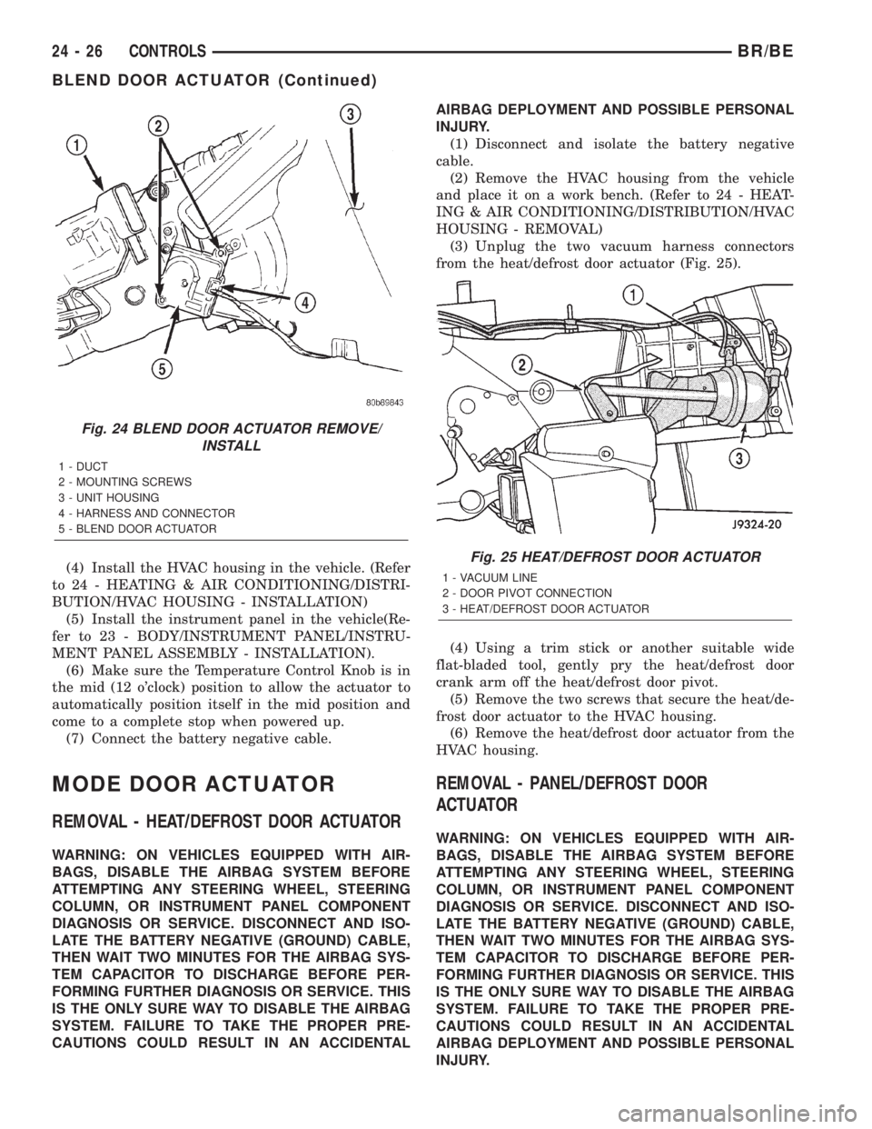
blend door actuator (Fig. 24).
(8) Remove the two mounting screws which secure
the actuator to the housing.
(9) Slide the blend door actuator off the blend door
shaft.
NOTE: A black plastic coupler may be attached to
the blend door shaft. Remove the coupler and
inspect for damage. Reinstall if there is no damage
found.
INSTALLATION
NOTE: Before installing the blend door actuator, be
certain that the blend door is not binding and is
capable of full travel in both directions.
(1) Align the actuator with the blend door shaft
and rotate the actuator to align it to the mounting
bosses on the HVAC housing.
(2) Align and install the actuator screws. Tighten
the mounting screws to 2.2 N´m (20 in. lbs.).
(3) Plug in the wire harness connector to the blend
door actuator.
BR/BECONTROLS 24 - 25
BLOWER MOTOR SWITCH (Continued)
Page 2147 of 2255
(4) Install the HVAC housing in the vehicle. (Refer
to 24 - HEATING & AIR CONDITIONING/DISTRI-
BUTION/HVAC HOUSING - INSTALLATION)
(5) Install the instrument panel in the vehicle(Re-
fer to 23 - BODY/INSTRUMENT PANEL/INSTRU-
MENT PANEL ASSEMBLY - INSTALLATION).
(6) Make sure the Temperature Control Knob is in
the mid (12 o'clock) position to allow the actuator to
automatically position itself in the mid position and
come to a complete stop when powered up.
(7) Connect the battery negative cable.
MODE DOOR ACTUATOR
REMOVAL - HEAT/DEFROST DOOR ACTUATOR
WARNING: ON VEHICLES EQUIPPED WITH AIR-
BAGS, DISABLE THE AIRBAG SYSTEM BEFORE
ATTEMPTING ANY STEERING WHEEL, STEERING
COLUMN, OR INSTRUMENT PANEL COMPONENT
DIAGNOSIS OR SERVICE. DISCONNECT AND ISO-
LATE THE BATTERY NEGATIVE (GROUND) CABLE,
THEN WAIT TWO MINUTES FOR THE AIRBAG SYS-
TEM CAPACITOR TO DISCHARGE BEFORE PER-
FORMING FURTHER DIAGNOSIS OR SERVICE. THIS
IS THE ONLY SURE WAY TO DISABLE THE AIRBAG
SYSTEM. FAILURE TO TAKE THE PROPER PRE-
CAUTIONS COULD RESULT IN AN ACCIDENTALAIRBAG DEPLOYMENT AND POSSIBLE PERSONAL
INJURY.
(1) Disconnect and isolate the battery negative
cable.
(2) Remove the HVAC housing from the vehicle
and place it on a work bench. (Refer to 24 - HEAT-
ING & AIR CONDITIONING/DISTRIBUTION/HVAC
HOUSING - REMOVAL)
(3) Unplug the two vacuum harness connectors
from the heat/defrost door actuator (Fig. 25).
(4) Using a trim stick or another suitable wide
flat-bladed tool, gently pry the heat/defrost door
crank arm off the heat/defrost door pivot.
(5) Remove the two screws that secure the heat/de-
frost door actuator to the HVAC housing.
(6) Remove the heat/defrost door actuator from the
HVAC housing.
REMOVAL - PANEL/DEFROST DOOR
ACTUATOR
WARNING: ON VEHICLES EQUIPPED WITH AIR-
BAGS, DISABLE THE AIRBAG SYSTEM BEFORE
ATTEMPTING ANY STEERING WHEEL, STEERING
COLUMN, OR INSTRUMENT PANEL COMPONENT
DIAGNOSIS OR SERVICE. DISCONNECT AND ISO-
LATE THE BATTERY NEGATIVE (GROUND) CABLE,
THEN WAIT TWO MINUTES FOR THE AIRBAG SYS-
TEM CAPACITOR TO DISCHARGE BEFORE PER-
FORMING FURTHER DIAGNOSIS OR SERVICE. THIS
IS THE ONLY SURE WAY TO DISABLE THE AIRBAG
SYSTEM. FAILURE TO TAKE THE PROPER PRE-
CAUTIONS COULD RESULT IN AN ACCIDENTAL
AIRBAG DEPLOYMENT AND POSSIBLE PERSONAL
INJURY.
Fig. 24 BLEND DOOR ACTUATOR REMOVE/
INSTALL
1 - DUCT
2 - MOUNTING SCREWS
3 - UNIT HOUSING
4 - HARNESS AND CONNECTOR
5 - BLEND DOOR ACTUATOR
Fig. 25 HEAT/DEFROST DOOR ACTUATOR
1 - VACUUM LINE
2 - DOOR PIVOT CONNECTION
3 - HEAT/DEFROST DOOR ACTUATOR
24 - 26 CONTROLSBR/BE
BLEND DOOR ACTUATOR (Continued)
Page 2148 of 2255

(1) Disconnect and isolate the battery negative
cable.
(2) Remove the instrument panel assembly from
the vehicle(Refer to 23 - BODY/INSTRUMENT PAN-
EL/INSTRUMENT PANEL ASSEMBLY - REMOV-
AL).
(3) Unplug the vacuum harness connector from the
panel/defrost door actuator (Fig. 26).
(4) Using a trim stick or another suitable wide
flat-bladed tool, gently pry the panel/defrost door
crank arm off the panel/defrost door pivot.
(5) Remove the two screws that secure the panel/
defrost door actuator to the HVAC housing.
(6) Remove the panel/defrost door actuator from
the HVAC housing.
INSTALLATION - HEAT/DEFROST DOOR
ACTUATOR
NOTE: Before installing the heat/defrost door actua-
tor, be certain that the heat/defrost door is not bind-
ing.
(1) Install the heat/defrost door actuator from the
HVAC housing. Tighten the actuator mounting
screws to 2.2 N´m (20 in. lbs.).
(2) Carefully snap the heat/defrost door crank arm
on the heat/defrost door pivot.(3) Plug in the two vacuum harness connectors to
the heat/defrost door actuator.
(4) Install the HVAC housing in the vehicle. (Refer
to 24 - HEATING & AIR CONDITIONING/DISTRI-
BUTION/HVAC HOUSING - INSTALLATION)
(5) Connect the battery negative cable.
INSTALLATION - PANEL/DEFROST DOOR
ACTUATOR
NOTE: Before installing the panel/defrost door
actuator, be certain that the panel/defrost door is
not binding.
(1) Install the panel/defrost door actuator on the
HVAC housing. Tighten the mounting screws to 2.2
N´m (20 in. lbs.).
(2) Carefully snap the panel/defrost door crank
arm on the panel/defrost door pivot.
(3) Plug the vacuum harness connector to the pan-
el/defrost door actuator.
(4) Install the instrument panel assembly in the
vehicle(Refer to 23 - BODY/INSTRUMENT PANEL/
INSTRUMENT PANEL ASSEMBLY - INSTALLA-
TION).
(5) Connect the battery negative cable.
RECIRCULATION DOOR
ACTUATOR
REMOVAL
WARNING: ON VEHICLES EQUIPPED WITH AIR-
BAGS, DISABLE THE AIRBAG SYSTEM BEFORE
ATTEMPTING ANY STEERING WHEEL, STEERING
COLUMN, OR INSTRUMENT PANEL COMPONENT
DIAGNOSIS OR SERVICE. DISCONNECT AND ISO-
LATE THE BATTERY NEGATIVE (GROUND) CABLE,
THEN WAIT TWO MINUTES FOR THE AIRBAG SYS-
TEM CAPACITOR TO DISCHARGE BEFORE PER-
FORMING FURTHER DIAGNOSIS OR SERVICE. THIS
IS THE ONLY SURE WAY TO DISABLE THE AIRBAG
SYSTEM. FAILURE TO TAKE THE PROPER PRE-
CAUTIONS COULD RESULT IN AN ACCIDENTAL
AIRBAG DEPLOYMENT AND POSSIBLE PERSONAL
INJURY.
(1) Disconnect and isolate the battery negative
cable.
(2) Remove the glove box from the instrument pan-
el(Refer to 23 - BODY/INSTRUMENT PANEL/IN-
STRUMENT PANEL ASSEMBLY - REMOVAL).
Fig. 26 PANEL/DEFROST DOOR ACTUATOR
1 - VACUUM LINE
2 - PANEL/DEFROST ACTUATOR
3 - SHAFT RETAINER
BR/BECONTROLS 24 - 27
MODE DOOR ACTUATOR (Continued)
Page 2155 of 2255
(2) Roll the instrument panel assembly up, and
fasten it properly to the vehicle(Refer to 23 - BODY/
INSTRUMENT PANEL/INSTRUMENT PANEL
ASSEMBLY - INSTALLATION).
HVAC HOUSING
REMOVAL
WARNING: ON VEHICLES EQUIPPED WITH AIR-
BAGS, DISABLE THE AIRBAG SYSTEM BEFORE
ATTEMPTING ANY STEERING WHEEL, STEERING
COLUMN, OR INSTRUMENT PANEL COMPONENT
DIAGNOSIS OR SERVICE. DISCONNECT AND ISO-
LATE THE BATTERY NEGATIVE (GROUND) CABLE,
THEN WAIT TWO MINUTES FOR THE AIRBAG SYS-
TEM CAPACITOR TO DISCHARGE BEFORE PER-
FORMING FURTHER DIAGNOSIS OR SERVICE. THIS
IS THE ONLY SURE WAY TO DISABLE THE AIRBAG
SYSTEM. FAILURE TO TAKE THE PROPER PRE-
CAUTIONS COULD RESULT IN AN ACCIDENTAL
AIRBAG DEPLOYMENT AND POSSIBLE PERSONAL
INJURY.
WARNING: IF THE VEHICLE IS EQUIPPED WITH AIR
CONDITIONING, REVIEW THE WARNINGS AND
CAUTIONS IN PLUMBING BEFORE PERFORMING
THE FOLLOWING OPERATION. (Refer to 24 - HEAT-
ING & AIR CONDITIONING/PLUMBING - WARNING)
(Refer to 24 - HEATING & AIR CONDITIONING/
PLUMBING - CAUTION)
The HVAC housing assembly must be removed
from the vehicle and disassembled for service access
of the heater core, a/c evaporator, and each of the
various mode control doors.
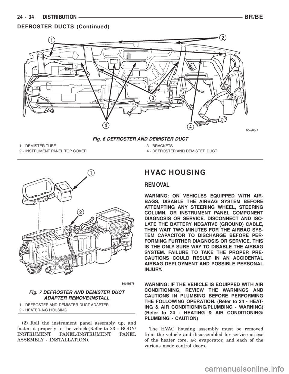
Fig. 6 DEFROSTER AND DEMISTER DUCT
1 - DEMISTER TUBE
2 - INSTRUMENT PANEL TOP COVER3 - BRACKETS
4 - DEFROSTER AND DEMISTER DUCT
Fig. 7 DEFROSTER AND DEMISTER DUCT
ADAPTER REMOVE/INSTALL
1 - DEFROSTER AND DEMISTER DUCT ADAPTER
2 - HEATER-A/C HOUSING
24 - 34 DISTRIBUTIONBR/BE
DEFROSTER DUCTS (Continued)
Page 2156 of 2255
(1) Disconnect and isolate the battery negative
cable.
(2) If the vehicle is not equipped with air condi-
tioning, go to Step 6. If the vehicle is equipped with
air conditioning, recover the refrigerant from the sys-
tem. (Refer to 24 - HEATING & AIR CONDITION-
ING/PLUMBING - STANDARD PROCEDURE -
REFRIGERANT RECOVERY)
(3) Remove the instrument panel from the vehicle.
Refer to Instrument Panel System for the procedures.
(4) Disconnect the liquid line refrigerant line fit-
ting from the evaporator inlet tube. (Refer to 24 -
HEATING & AIR CONDITIONING/PLUMBING -
STANDARD PROCEDURE - A/C LINE COUPLERS)
Install plugs in, or tape over all of the opened refrig-
erant line fittings.
(5) Remove the accumulator. (Refer to 24 - HEAT-
ING & AIR CONDITIONING/PLUMBING/ACCU-
MULATOR - REMOVAL) Install plugs in, or tape
over all of the opened refrigerant line fittings.
(6) Drain the engine cooling system(Refer to 7 -
COOLING - STANDARD PROCEDURE) and (Refer
to 7 - COOLING - STANDARD PROCEDURE).
(7) Disconnect the heater hoses from the heater
core tubes. Refer to Cooling for the procedures.
Install plugs in, or tape over the opened heater core
tubes.
(8) Remove the Powertrain Control Module (PCM)
from the dash panel and set it aside, but do not
unplug the PCM wire harness connectors. Refer to
Electronic Control Modules for the procedures.
(9) Remove the nuts from the HVAC housing
mounting studs on the engine compartment side of
the dash panel.
(10) Remove the nuts that secure the HVAC hous-
ing to the mounting studs on the passenger compart-
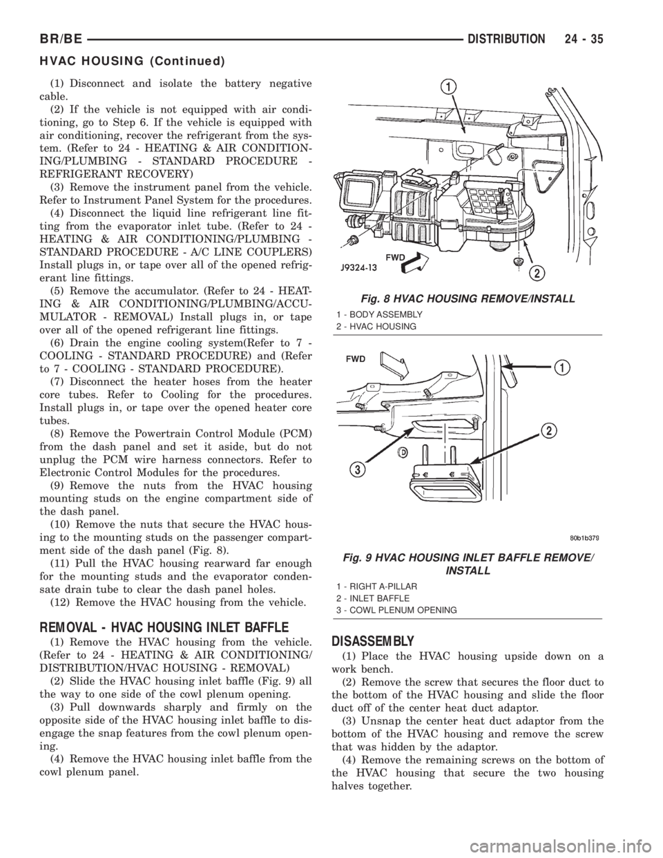
ment side of the dash panel (Fig. 8).
(11) Pull the HVAC housing rearward far enough
for the mounting studs and the evaporator conden-
sate drain tube to clear the dash panel holes.
(12) Remove the HVAC housing from the vehicle.
REMOVAL - HVAC HOUSING INLET BAFFLE
(1) Remove the HVAC housing from the vehicle.
(Refer to 24 - HEATING & AIR CONDITIONING/
DISTRIBUTION/HVAC HOUSING - REMOVAL)
(2) Slide the HVAC housing inlet baffle (Fig. 9) all
the way to one side of the cowl plenum opening.
(3) Pull downwards sharply and firmly on the
opposite side of the HVAC housing inlet baffle to dis-
engage the snap features from the cowl plenum open-
ing.
(4) Remove the HVAC housing inlet baffle from the
cowl plenum panel.DISASSEMBLY
(1) Place the HVAC housing upside down on a
work bench.
(2) Remove the screw that secures the floor duct to
the bottom of the HVAC housing and slide the floor
duct off of the center heat duct adaptor.
(3) Unsnap the center heat duct adaptor from the
bottom of the HVAC housing and remove the screw
that was hidden by the adaptor.
(4) Remove the remaining screws on the bottom of
the HVAC housing that secure the two housing
halves together.
Fig. 8 HVAC HOUSING REMOVE/INSTALL
1 - BODY ASSEMBLY
2 - HVAC HOUSING
Fig. 9 HVAC HOUSING INLET BAFFLE REMOVE/
INSTALL
1 - RIGHT A-PILLAR
2 - INLET BAFFLE
3 - COWL PLENUM OPENING
BR/BEDISTRIBUTION 24 - 35
HVAC HOUSING (Continued)
Page 2157 of 2255
(5) Place the HVAC housing right side up on the
work bench.
(6) Separate the top half of the HVAC housing
from the bottom half and set it aside.
ASSEMBLY
(1) Position the top half of the HVAC housing over
the bottom half. Be certain that the mode door pivot
pins are properly inserted in their pivot holes.
(2) Place the HVAC housing upside down on the
work bench.
(3) Install and tighten the screws on the bottom of
the HVAC housing that secure the two housing
halves together. Tighten the screws to 2.2 N´m (20 in.
lbs.).
(4) Snap the center heat duct adaptor onto the bot-
tom of the HVAC housing.
(5) Slide the floor duct onto the center heat duct
adaptor and secure it with a screw to the bottom of
the HVAC housing. Tighten the mounting screw to
2.2 N´m (20 in. lbs.).
INSTALLATION
(1) Position the HVAC housing to the dash panel.
Be certain that the evaporator condensate drain tube
and the housing mounting studs are inserted into
their correct mounting holes.
(2) Install the nuts that secure the HVAC housing
to the mounting studs on the passenger compartment
side of the dash panel. Tighten the nuts to 4.5 N´m
(40 in. lbs.).
(3) Install and tighten the nuts onto the HVAC
housing mounting studs on the engine compartment
side of the dash panel. Tighten the nuts to 7 N´m (60
in. lbs.).
(4) Unplug or remove the tape from the heater
core tubes. Connect the heater hoses to the heater
core tubes and fill the engine cooling system(Refer to
7 - COOLING - STANDARD PROCEDURE) and
(Refer to 7 - COOLING - STANDARD PROCE-
DURE).
(5) If the vehicle is not equipped with air condi-
tioning, go to Step 10. If the vehicle is equipped with
air conditioning, install the accumulator. (Refer to 24
- HEATING & AIR CONDITIONING/PLUMBING/
ACCUMULATOR - INSTALLATION) Connect the
accumulator inlet tube coupler to the evaporator out-
let tube. (Refer to 24 - HEATING & AIR CONDI-
TIONING/PLUMBING - STANDARD PROCEDURE -
A/C LINE COUPLERS)
(6) Unplug or remove the tape from the liquid line
and the evaporator inlet tube fittings. Connect the
liquid line coupler to the evaporator inlet tube. (Refer
to 24 - HEATING & AIR CONDITIONING/PLUMB-
ING - STANDARD PROCEDURE - A/C LINE COU-
PLERS)(7) Evacuate the refrigerant system. (Refer to 24 -
HEATING & AIR CONDITIONING/PLUMBING -
STANDARD PROCEDURE - REFRIGERANT SYS-
TEM EVACUATE)
(8) Charge the refrigerant system. (Refer to 24 -
HEATING & AIR CONDITIONING/PLUMBING -
STANDARD PROCEDURE - REFRIGERANT SYS-
TEM CHARGE)
(9) Reinstall the PCM to the dash panel. Refer to
Electronic Control Modules for the procedures.
(10) Reinstall the instrument panel in the vehi-
cle(Refer to 23 - BODY/INSTRUMENT PANEL/IN-
STRUMENT PANEL ASSEMBLY -
INSTALLATION).
(11) Connect the battery negative cable.
(12) Start the engine and check for proper opera-
tion of the heating and air conditioning systems.
INSTALLATION - HVAC HOUSING INLET
BAFFLE
(1) Install the HVAC housing inlet baffle in the
cowl plenum panel.
(2) Slide the HVAC housing inlet baffle to engage
the snap features.
(3) Make certain that the snap features on each
side of the adapter are fully engaged with the sides
of the plenum panel opening. This must be a water
tight connection to prevent leaks.
(4) Install the HVAC housing in the vehicle. (Refer
to 24 - HEATING & AIR CONDITIONING/DISTRI-
BUTION/HVAC HOUSING - INSTALLATION)
INSTRUMENT PANEL
DEMISTER DUCTS
REMOVAL
The defroster duct and the main demister duct are
a single molded plastic unit. The defroster outlet
grilles are heat-staked to the defroster outlets and
cannot be serviced separately. The demister tubes on
each end of the main demister duct are only serviced
in the instrument panel assembly. (Refer to 24 -
HEATING & AIR CONDITIONING/DISTRIBUTION/
DEFROSTER DUCTS - REMOVAL)
INSTALLATION
The defroster duct and the main demister duct are
a single molded plastic unit. The defroster outlet
grilles are heat-staked to the defroster outlets and
cannot be serviced separately. The demister tubes on
each end of the mail demister duct are only serviced
in the instrument panel assembly(Refer to 24 -
HEATING & AIR CONDITIONING/DISTRIBUTION/
DEFROSTER DUCTS - INSTALLATION).
24 - 36 DISTRIBUTIONBR/BE
HVAC HOUSING (Continued)
Page 2158 of 2255
INSTRUMENT PANEL DUCTS
REMOVAL
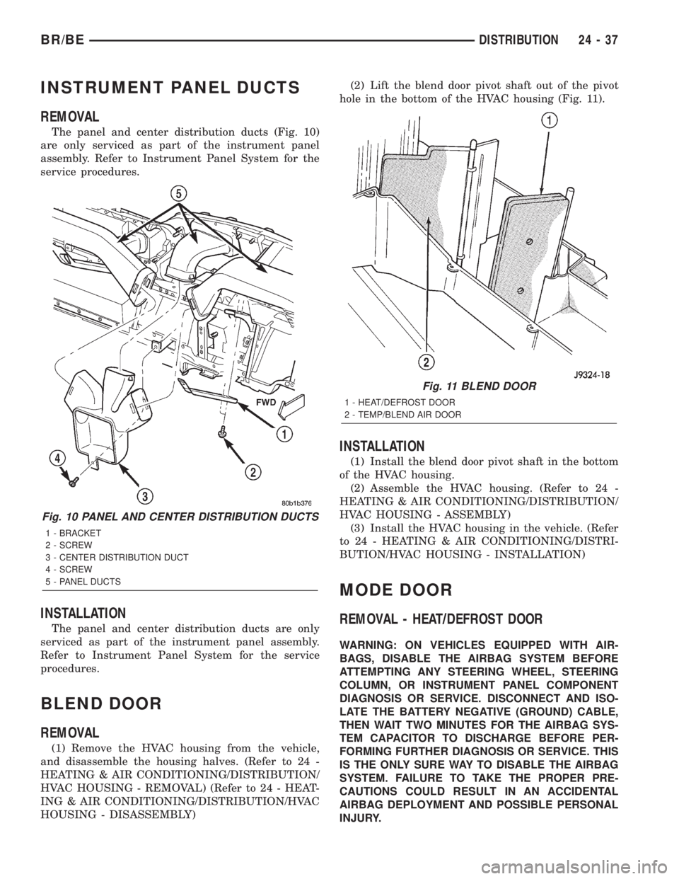
The panel and center distribution ducts (Fig. 10)
are only serviced as part of the instrument panel
assembly. Refer to Instrument Panel System for the
service procedures.
INSTALLATION
The panel and center distribution ducts are only
serviced as part of the instrument panel assembly.
Refer to Instrument Panel System for the service
procedures.
BLEND DOOR
REMOVAL
(1) Remove the HVAC housing from the vehicle,
and disassemble the housing halves. (Refer to 24 -
HEATING & AIR CONDITIONING/DISTRIBUTION/
HVAC HOUSING - REMOVAL) (Refer to 24 - HEAT-
ING & AIR CONDITIONING/DISTRIBUTION/HVAC
HOUSING - DISASSEMBLY)(2) Lift the blend door pivot shaft out of the pivot
hole in the bottom of the HVAC housing (Fig. 11).
INSTALLATION
(1) Install the blend door pivot shaft in the bottom
of the HVAC housing.
(2) Assemble the HVAC housing. (Refer to 24 -
HEATING & AIR CONDITIONING/DISTRIBUTION/
HVAC HOUSING - ASSEMBLY)
(3) Install the HVAC housing in the vehicle. (Refer
to 24 - HEATING & AIR CONDITIONING/DISTRI-
BUTION/HVAC HOUSING - INSTALLATION)
MODE DOOR
REMOVAL - HEAT/DEFROST DOOR
WARNING: ON VEHICLES EQUIPPED WITH AIR-
BAGS, DISABLE THE AIRBAG SYSTEM BEFORE
ATTEMPTING ANY STEERING WHEEL, STEERING
COLUMN, OR INSTRUMENT PANEL COMPONENT
DIAGNOSIS OR SERVICE. DISCONNECT AND ISO-
LATE THE BATTERY NEGATIVE (GROUND) CABLE,
THEN WAIT TWO MINUTES FOR THE AIRBAG SYS-
TEM CAPACITOR TO DISCHARGE BEFORE PER-
FORMING FURTHER DIAGNOSIS OR SERVICE. THIS
IS THE ONLY SURE WAY TO DISABLE THE AIRBAG
SYSTEM. FAILURE TO TAKE THE PROPER PRE-
CAUTIONS COULD RESULT IN AN ACCIDENTAL
AIRBAG DEPLOYMENT AND POSSIBLE PERSONAL
INJURY.
Fig. 10 PANEL AND CENTER DISTRIBUTION DUCTS
1 - BRACKET
2 - SCREW
3 - CENTER DISTRIBUTION DUCT
4 - SCREW
5 - PANEL DUCTS
Fig. 11 BLEND DOOR
1 - HEAT/DEFROST DOOR
2 - TEMP/BLEND AIR DOOR
BR/BEDISTRIBUTION 24 - 37