2002 DODGE RAM hood open
[x] Cancel search: hood openPage 1968 of 2255
BODY
TABLE OF CONTENTS
page page
BODY
WARNING
SAFETY PRECAUTIONS AND WARNINGS . . . 1
DIAGNOSIS AND TESTING
DIAGNOSIS AND TESTING - WATER LEAKS . 2
DIAGNOSIS AND TESTING - WIND NOISE . . . 3
SPECIFICATIONS
WELD LOCATIONS.....................4
STRUCTURAL ADHESIVE LOCATIONS.....44
BODY SEALER LOCATIONS.............47
BODY GAP AND FLUSH MEASUREMENTS . . 56
BODY OPENING DIMENSIONS...........60TORQUE SPECIFICATIONS.............61
DECKLID/HATCH/LIFTGATE/TAILGATE.......63
DOOR - FRONT.........................68
DOOR - CARGO.........................77
EXTERIOR.............................86
HOOD................................100
INSTRUMENT PANEL SYSTEM............105
INTERIOR.............................118
PAINT................................129
SEATS...............................131
STATIONARY GLASS....................145
WEATHERSTRIP/SEALS..................151
BODY
WARNING
SAFETY PRECAUTIONS AND WARNINGS
WARNING: USE AN OSHA APPROVED BREATHING
FILTER WHEN SPRAYING PAINT OR SOLVENTS IN
A CONFINED AREA. PERSONAL INJURY CAN
RESULT.
²AVOID PROLONGED SKIN CONTACT WITH
PETROLEUM OR ALCOHOL ± BASED CLEANING
SOLVENTS. PERSONAL INJURY CAN RESULT.
²DO NOT STAND UNDER A HOISTED VEHICLE
THAT IS NOT PROPERLY SUPPORTED ON SAFETY
STANDS. PERSONAL INJURY CAN RESULT.CAUTION: When holes must be drilled or punched
in an inner body panel, verify depth of space to the
outer body panel, electrical wiring, or other compo-
nents. Damage to vehicle can result.
²Do not weld exterior panels unless combustible
material on the interior of vehicle is removed from
the repair area. Fire or hazardous conditions, can
result.
²Always have a fire extinguisher ready for use
when welding.
²Disconnect the negative (-) cable clamp from
the battery when servicing electrical components
that are live when the ignition is OFF. Damage to
electrical system can result.
²Do not use abrasive chemicals or compounds
on painted surfaces. Damage to finish can result.
²Do not use harsh alkaline based cleaning sol-
vents on painted or upholstered surfaces. Damage
to finish or color can result.
²Do not hammer or pound on plastic trim panel
when servicing interior trim. Plastic panels can
break.
BR/BEBODY 23 - 1
Page 2029 of 2255
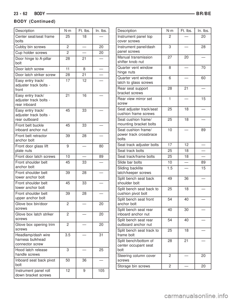
Description N´m Ft. lbs. In. lbs.
Center seat/seat frame
bolts25 18 Ð
Cubby bin screws 2 Ð 20
Cup holder screws 2 Ð 20
Door hinge to A-pillar
bolt28 21 Ð
Door latch screw 11 8 Ð
Door latch striker screw 28 21 Ð
Easy entry track/
adjuster track bolts -
front17 12 Ð
Easy entry track/
adjuster track bolts -
rear inboard21 16 Ð
Easy entry track/
adjuster track bolts -
rear outboard45 33 Ð
Front belt buckle
inboard anchor nut45 33 Ð
Front belt retractor
anchor bolt39 28 Ð
Front door glass lift
plate nuts9Ð80
Front door latch screws 10 Ð 89
Front shoulder belt
anchor bolt45 33 Ð
Front shoulder belt
lower anchor bolt39 28 Ð
Front shoulder belt
lower anchor bolt45 33 Ð
Front shoulder belt
upper anchor bolt39 28 Ð
Glove box bin/door
screws2Ð20
Glove box latch striker
screws2Ð20
Glove box opening trim
screws2Ð20
Headlamp/dash wire
harness bulkhead
connector screw3.5 Ð 31
Hood latch release
handle screws3Ð25
Inboard seat back pivot
bolt50 36 Ð
Instrument panel roll
down bracket screws12 9 105Description N´m Ft. lbs. In. lbs.
Instrument panel top
cover screws2Ð20
Instrument panel/dash
panel screws3Ð28
Manual transmission
shifter knob nut27 20 Ð
Quarter vent window
hinge nuts8Ð70
Quarter vent window
latch to glass screws6Ð60
Rear seat support
bracket screws28 21 Ð
Rear view mirror set
screw1Ð15
Seat adjuster track/seat
cushion frame screws25 18 Ð
Seat cushion frame/
mounting bracket bolts25 18 Ð
Seat cushion frame/
power track crossbrace
bolts10 Ð 89
Seat track adjuster bolts 17 12 Ð
Seat track bolts 25 18 Ð
Seat track/frame bolts 25 18 Ð
Slide bar bolts 10 Ð 89
Sliding backlite
latch/keeper screws1.5 Ð 15
Split bench seat back
shoulder bolt49 36 Ð
Split bench seat back to
cushion pivot bolt25 18 Ð
Split bench seat front
anchor bolt54 40 Ð
Split bench seat rear
inboard anchor nut40 30 Ð
Split bench seat rear
outboard anchor nut54 40 Ð
Split bench seat track to
frame bolt25 18 Ð
Split bench/bottom of
center occupant seat
bolt28 21 Ð
Steering column cover
screws2Ð20
Storage bin screws 2 Ð 20
23 - 62 BODYBR/BE
BODY (Continued)
Page 2057 of 2255
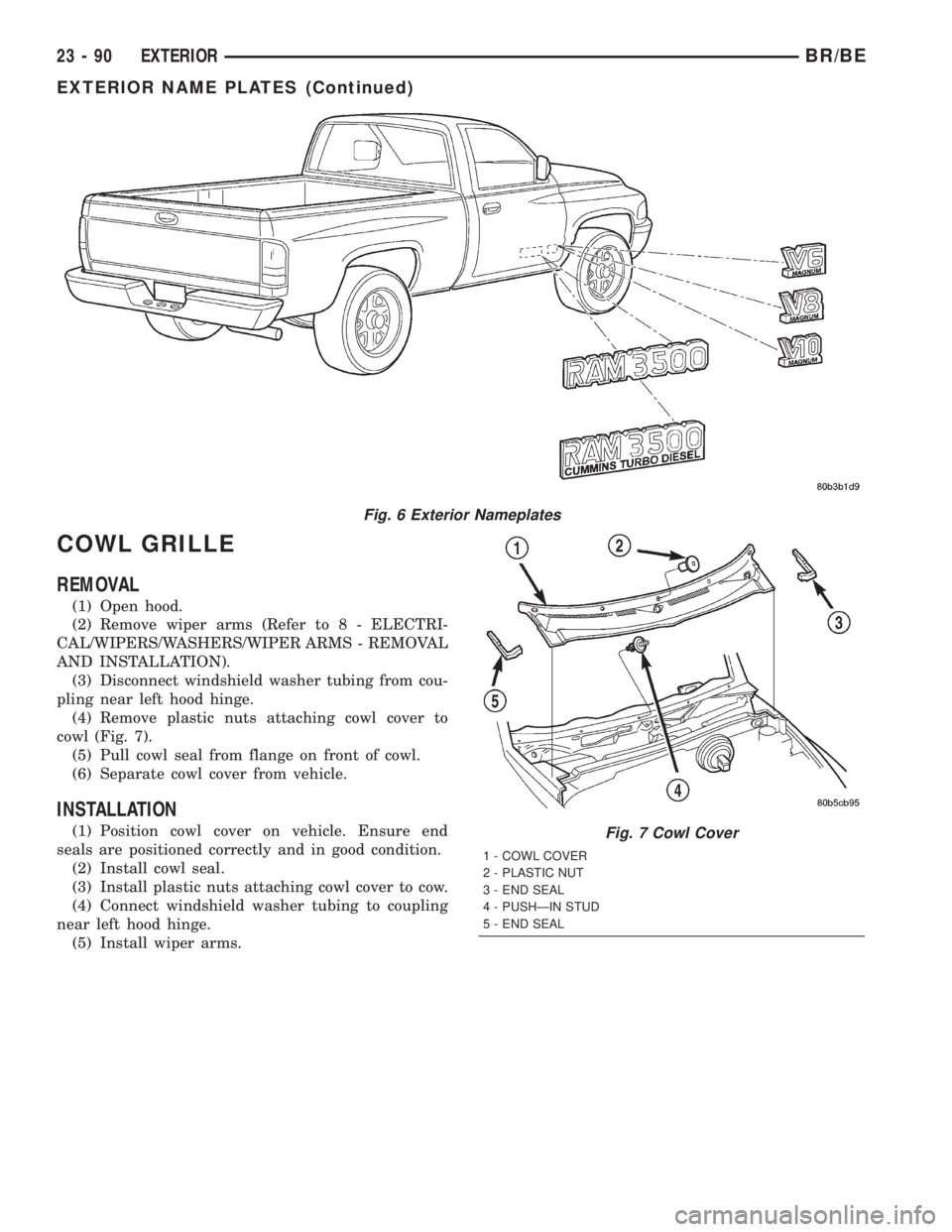
COWL GRILLE
REMOVAL
(1) Open hood.
(2) Remove wiper arms (Refer to 8 - ELECTRI-
CAL/WIPERS/WASHERS/WIPER ARMS - REMOVAL
AND INSTALLATION).
(3) Disconnect windshield washer tubing from cou-
pling near left hood hinge.
(4) Remove plastic nuts attaching cowl cover to
cowl (Fig. 7).
(5) Pull cowl seal from flange on front of cowl.
(6) Separate cowl cover from vehicle.
INSTALLATION
(1) Position cowl cover on vehicle. Ensure end
seals are positioned correctly and in good condition.
(2) Install cowl seal.
(3) Install plastic nuts attaching cowl cover to cow.
(4) Connect windshield washer tubing to coupling
near left hood hinge.
(5) Install wiper arms.
Fig. 6 Exterior Nameplates
Fig. 7 Cowl Cover
1 - COWL COVER
2 - PLASTIC NUT
3 - END SEAL
4 - PUSHÐIN STUD
5 - END SEAL
23 - 90 EXTERIORBR/BE
EXTERIOR NAME PLATES (Continued)
Page 2058 of 2255
ROOF JOINT MOLDING
REMOVAL
(1) Warm the roof joint molding and roof panel to
approximately 38ÉC (100ÉF) using a suitable heat
lamp or heat gun.
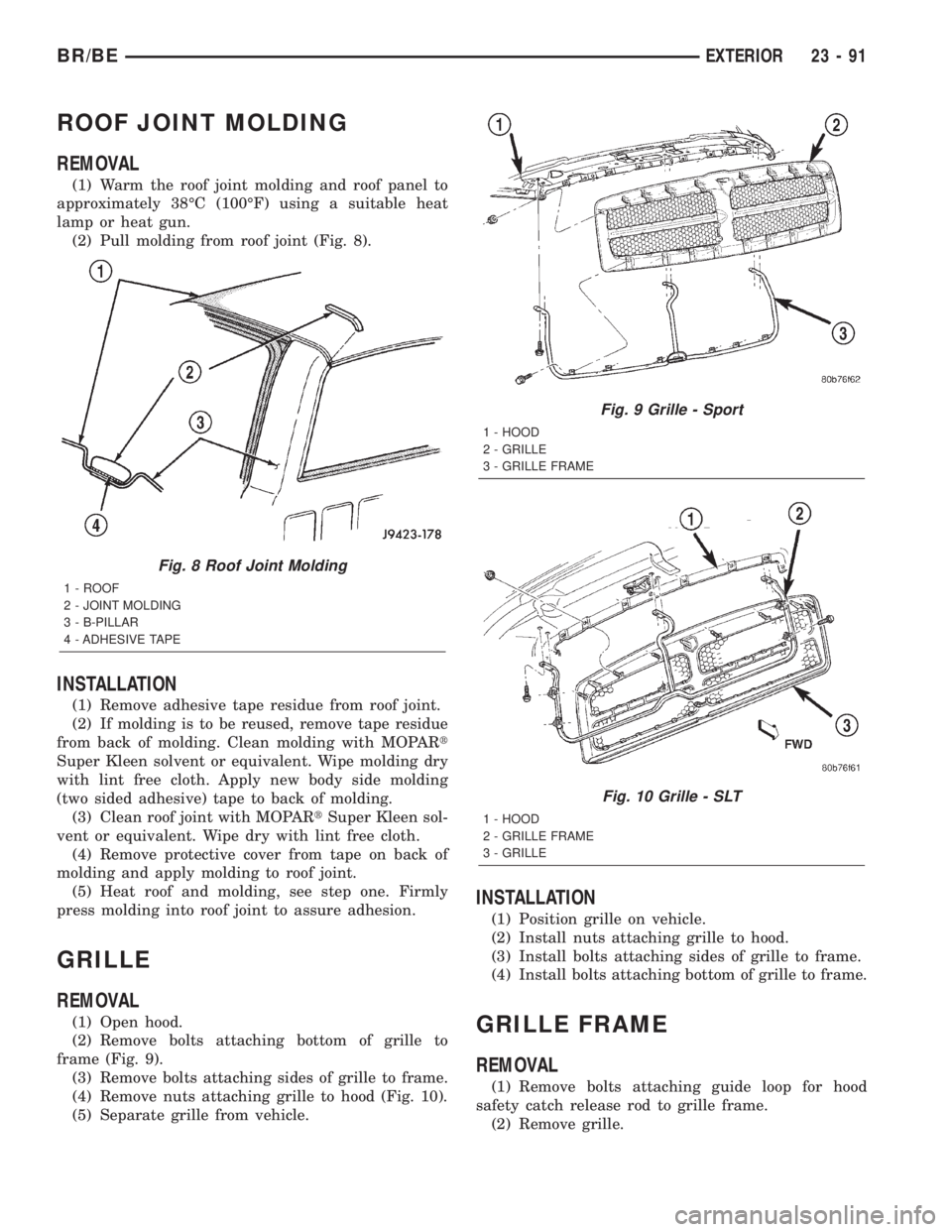
(2) Pull molding from roof joint (Fig. 8).
INSTALLATION
(1) Remove adhesive tape residue from roof joint.
(2) If molding is to be reused, remove tape residue
from back of molding. Clean molding with MOPARt
Super Kleen solvent or equivalent. Wipe molding dry
with lint free cloth. Apply new body side molding
(two sided adhesive) tape to back of molding.
(3) Clean roof joint with MOPARtSuper Kleen sol-
vent or equivalent. Wipe dry with lint free cloth.
(4) Remove protective cover from tape on back of
molding and apply molding to roof joint.
(5) Heat roof and molding, see step one. Firmly
press molding into roof joint to assure adhesion.
GRILLE
REMOVAL
(1) Open hood.
(2) Remove bolts attaching bottom of grille to
frame (Fig. 9).
(3) Remove bolts attaching sides of grille to frame.
(4) Remove nuts attaching grille to hood (Fig. 10).
(5) Separate grille from vehicle.
INSTALLATION
(1) Position grille on vehicle.
(2) Install nuts attaching grille to hood.
(3) Install bolts attaching sides of grille to frame.
(4) Install bolts attaching bottom of grille to frame.
GRILLE FRAME
REMOVAL
(1) Remove bolts attaching guide loop for hood
safety catch release rod to grille frame.
(2) Remove grille.
Fig. 8 Roof Joint Molding
1 - ROOF
2 - JOINT MOLDING
3 - B-PILLAR
4 - ADHESIVE TAPE
Fig. 9 Grille - Sport
1 - HOOD
2 - GRILLE
3 - GRILLE FRAME
Fig. 10 Grille - SLT
1 - HOOD
2 - GRILLE FRAME
3 - GRILLE
BR/BEEXTERIOR 23 - 91
Page 2059 of 2255
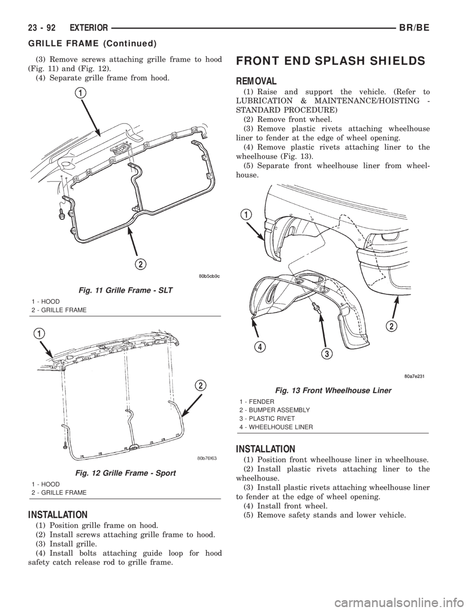
(3) Remove screws attaching grille frame to hood
(Fig. 11) and (Fig. 12).
(4) Separate grille frame from hood.
INSTALLATION
(1) Position grille frame on hood.
(2) Install screws attaching grille frame to hood.
(3) Install grille.
(4) Install bolts attaching guide loop for hood
safety catch release rod to grille frame.
FRONT END SPLASH SHIELDS
REMOVAL
(1) Raise and support the vehicle. (Refer to
LUBRICATION & MAINTENANCE/HOISTING -
STANDARD PROCEDURE)
(2) Remove front wheel.
(3) Remove plastic rivets attaching wheelhouse
liner to fender at the edge of wheel opening.
(4) Remove plastic rivets attaching liner to the
wheelhouse (Fig. 13).
(5) Separate front wheelhouse liner from wheel-
house.
INSTALLATION
(1) Position front wheelhouse liner in wheelhouse.
(2) Install plastic rivets attaching liner to the
wheelhouse.
(3) Install plastic rivets attaching wheelhouse liner
to fender at the edge of wheel opening.
(4) Install front wheel.
(5) Remove safety stands and lower vehicle.
Fig. 11 Grille Frame - SLT
1 - HOOD
2 - GRILLE FRAME
Fig. 12 Grille Frame - Sport
1 - HOOD
2 - GRILLE FRAME
Fig. 13 Front Wheelhouse Liner
1 - FENDER
2 - BUMPER ASSEMBLY
3 - PLASTIC RIVET
4 - WHEELHOUSE LINER
23 - 92 EXTERIORBR/BE
GRILLE FRAME (Continued)
Page 2067 of 2255
HOOD
TABLE OF CONTENTS
page page
HINGE
REMOVAL............................100
INSTALLATION........................100
HOOD
REMOVAL............................101
INSTALLATION........................101
ADJUSTMENTS
ADJUSTMENT.......................101
LATCH
REMOVAL............................102
INSTALLATION........................102
ADJUSTMENTS
ADJUSTMENT.......................102
LATCH RELEASE CABLE
REMOVAL............................103INSTALLATION........................103
LATCH STRIKER
REMOVAL............................103
INSTALLATION........................103
ADJUSTMENTS
ADJUSTMENT.......................103
SAFETY LATCH
REMOVAL............................104
INSTALLATION........................104
SILENCER PAD
REMOVAL............................104
INSTALLATION........................104
HINGE
REMOVAL
(1) Open hood and support the side that requires
hinge replacement.
(2) Mark all bolt and hinge attachment locations
with a grease pencil or equivalent to provide refer-
ence marks for installation.
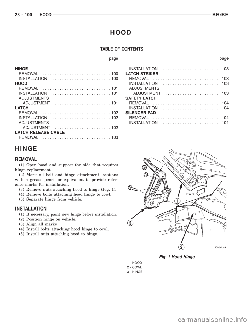
(3) Remove nuts attaching hood to hinge (Fig. 1).
(4) Remove bolts attaching hood hinge to cowl.
(5) Separate hinge from vehicle.
INSTALLATION
(1)If necessary, paint new hinge before installation.
(2) Position hinge on vehicle.
(3) Align all marks
(4) Install bolts attaching hood hinge to cowl.
(5) Install nuts attaching hood to hinge.
Fig. 1 Hood Hinge
1 - HOOD
2 - COWL
3 - HINGE
23 - 100 HOODBR/BE
Page 2070 of 2255
LATCH RELEASE CABLE
REMOVAL
(1) Remove hood latch (Refer to 23 - BODY/HOOD/
LATCH - REMOVAL).
(2) Disconnect release cable from hood latch.
(3) Detach the release cable from the retainer clips
in the engine compartment.
(4) Separate the release cable grommet from the
dash panel hole.
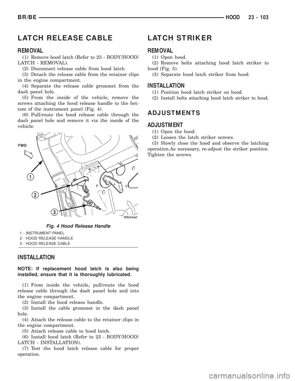
(5) From the inside of the vehicle, remove the
screws attaching the hood release handle to the bot-
tom of the instrument panel (Fig. 4).
(6) Pull/route the hood release cable through the
dash panel hole and remove it via the inside of the
vehicle.
INSTALLATION
NOTE: If replacement hood latch is also being
installed, ensure that it is thoroughly lubricated.
(1) From inside the vehicle, pull/route the hood
release cable through the dash panel hole and into
the engine compartment.
(2) Install the hood release handle.
(3) Install the cable grommet in the dash panel
hole.
(4) Attach the release cable to the retainer clips in
the engine compartment.
(5) Attach release cable to hood latch.
(6) Install hood latch (Refer to 23 - BODY/HOOD/
LATCH - INSTALLATION).
(7) Test the hood latch release cable for proper
operation.
LATCH STRIKER
REMOVAL
(1) Open hood.
(2) Remove bolts attaching hood latch striker to
hood (Fig. 5).
(3) Separate hood latch striker from hood.
INSTALLATION
(1) Position hood latch striker on hood.
(2)
Install bolts attaching hood latch striker to hood.
ADJUSTMENTS
ADJUSTMENT
(1) Open the hood.
(2) Loosen the latch striker screws.
(3) Slowly close the hood and observe the latching
operation.As necessary, re-adjust the striker position.
Tighten the screws.
Fig. 4 Hood Release Handle
1 - INSTRUMENT PANEL
2 - HOOD RELEASE HANDLE
3 - HOOD RELEASE CABLE
BR/BEHOOD 23 - 103
Page 2071 of 2255
SAFETY LATCH
REMOVAL
(1) Open hood.
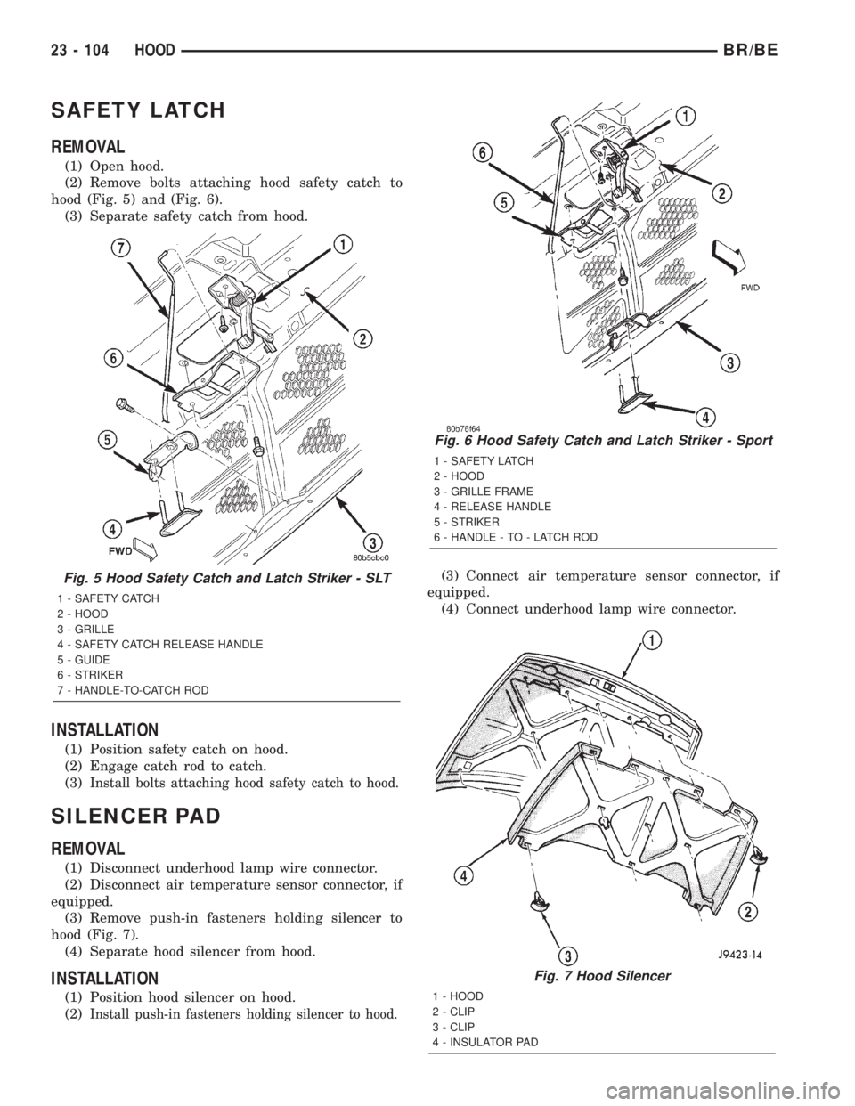
(2) Remove bolts attaching hood safety catch to
hood (Fig. 5) and (Fig. 6).
(3) Separate safety catch from hood.
INSTALLATION
(1) Position safety catch on hood.
(2) Engage catch rod to catch.
(3)
Install bolts attaching hood safety catch to hood.
SILENCER PAD
REMOVAL
(1) Disconnect underhood lamp wire connector.
(2) Disconnect air temperature sensor connector, if
equipped.
(3) Remove push-in fasteners holding silencer to
hood (Fig. 7).
(4) Separate hood silencer from hood.
INSTALLATION
(1) Position hood silencer on hood.
(2)
Install push-in fasteners holding silencer to hood.
(3) Connect air temperature sensor connector, if
equipped.
(4) Connect underhood lamp wire connector.
Fig. 6 Hood Safety Catch and Latch Striker - Sport
1 - SAFETY LATCH
2 - HOOD
3 - GRILLE FRAME
4 - RELEASE HANDLE
5 - STRIKER
6 - HANDLE - TO - LATCH ROD
Fig. 7 Hood Silencer
1 - HOOD
2 - CLIP
3 - CLIP
4 - INSULATOR PAD
Fig. 5 Hood Safety Catch and Latch Striker - SLT
1 - SAFETY CATCH
2 - HOOD
3 - GRILLE
4 - SAFETY CATCH RELEASE HANDLE
5 - GUIDE
6 - STRIKER
7 - HANDLE-TO-CATCH ROD
23 - 104 HOODBR/BE