2002 DODGE RAM hood open
[x] Cancel search: hood openPage 2072 of 2255
INSTRUMENT PANEL SYSTEM
TABLE OF CONTENTS
page page
INSTRUMENT PANEL SYSTEM
DESCRIPTION........................105
OPERATION..........................106
ASH RECEIVER
REMOVAL............................107
INSTALLATION........................107
CLUSTER BEZEL
REMOVAL............................108
INSTALLATION........................108
CUBBY BIN
REMOVAL............................108
INSTALLATION........................109
CUP HOLDER
REMOVAL............................109
INSTALLATION........................110
GLOVE BOX
REMOVAL
REMOVAL..........................110
DISASSEMBLY - GLOVE BOX...........110
ASSEMBLY - GLOVE BOX................111INSTALLATION........................111
GLOVE BOX LATCH STRIKER
REMOVAL............................111
INSTALLATION........................112
GLOVE BOX OPENING UPPER TRIM
REMOVAL............................112
INSTALLATION........................112
INSTRUMENT PANEL TOP COVER
REMOVAL............................113
INSTALLATION........................113
STEERING COLUMN OPENING COVER
REMOVAL............................113
INSTALLATION........................114
STORAGE BIN
REMOVAL............................114
INSTALLATION........................114
INSTRUMENT PANEL ASSEMBLY
REMOVAL............................115
INSTALLATION........................117
INSTRUMENT PANEL SYSTEM
DESCRIPTION
The instrument panel is located at the front of the
passenger compartment. This instrument panel is
molded from a blend of various plastics that are
mechanically attached to the vehicle. Colors are
molded into the plastic components to minimize
appearance degradation from scratches or abrasions.
The panel components are internally ribbed and riv-
eted to steel reinforcements for additional structural
integrity and dimensional stability. The instrument
panel surface components are designed to deform
upon impact without breaking. This type of construc-
tion provides improved energy absorption which, in
conjunction with the dual airbags and seat belts,
helps to improve occupant protection.
The top of the instrument panel is secured to the
top of the dash panel near the base of the windshield
using screws. An end bracket integral to each end of
the instrument panel structure is secured to each
cowl side inner panel with a screw. A stamped metal
bracket supports the center of the instrument panel
by securing it to the top of the floor panel transmis-
sion tunnel below the instrument panel with screws.
The instrument cluster, radio, heater-air conditioner
control, passenger airbag, glove box, electrical junc-tion block, Central Timer Module (CTM), accessory
switches, ash receiver, cigar lighter, accessory power
outlet, park brake release handle, inside hood release
handle, as well as numerous other components are
secured to and supported by this unit.
The instrument panel for this vehicle includes the
following major features:
²Cluster Bezel- This molded plastic bezel is
secured with snap clips to the instrument panel sup-
porting structure. It trims out the edges of the head-
lamp switch, instrument cluster, radio, heater-air
conditioner controls, passenger airbag on-off switch,
and the heated seat switches on vehicles so equipped.
On vehicles without the heated seat option, a small
storage cubby bin is provided in the cluster bezel.
This bezel also incorporates three completely adjust-
able panel outlets for the climate control system, and
fills the opening between the instrument cluster and
the top of the steering column where it passes
through the instrument panel.
²Cup Holder/Storage Bin- Vehicles equipped
with an automatic transmission feature a latching
fold-down, adjustable cup holder located on the lower
instrument panel between the glove box and the ash
receiver. Vehicles equipped with a manual transmis-
sion have a lighted storage bin on the instrument
panel in place of the cup holder.
BR/BEINSTRUMENT PANEL SYSTEM 23 - 105
Page 2074 of 2255
ASH RECEIVER
REMOVAL
WARNING: ON VEHICLES EQUIPPED WITH AIR-
BAGS, DISABLE THE AIRBAG SYSTEM BEFORE
ATTEMPTING ANY STEERING WHEEL, STEERING
COLUMN, SEAT BELT TENSIONER, OR INSTRU-
MENT PANEL COMPONENT DIAGNOSIS OR SER-
VICE. DISCONNECT AND ISOLATE THE BATTERY
NEGATIVE (GROUND) CABLE, THEN WAIT TWO
MINUTES FOR THE AIRBAG SYSTEM CAPACITOR
TO DISCHARGE BEFORE PERFORMING FURTHER
DIAGNOSIS OR SERVICE. THIS IS THE ONLY SURE
WAY TO DISABLE THE AIRBAG SYSTEM. FAILURE
TO TAKE THE PROPER PRECAUTIONS COULD
RESULT IN ACCIDENTAL AIRBAG DEPLOYMENT
AND POSSIBLE PERSONAL INJURY.
(1) Disconnect and isolate the battery negative
cable.
(2) Open the instrument panel ash receiver.
(3) From the open position, close the ash receiver
slightly and pull it straight back far enough to disen-
gage it from the pivot pins in the lower instrument
panel.
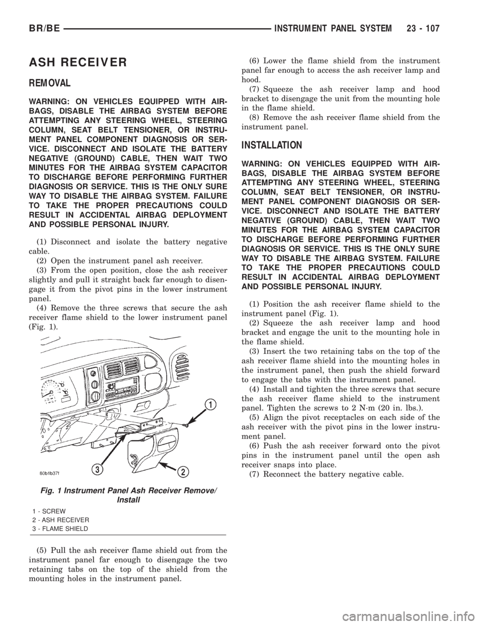
(4) Remove the three screws that secure the ash
receiver flame shield to the lower instrument panel
(Fig. 1).
(5) Pull the ash receiver flame shield out from the
instrument panel far enough to disengage the two
retaining tabs on the top of the shield from the
mounting holes in the instrument panel.(6) Lower the flame shield from the instrument
panel far enough to access the ash receiver lamp and
hood.
(7) Squeeze the ash receiver lamp and hood
bracket to disengage the unit from the mounting hole
in the flame shield.
(8) Remove the ash receiver flame shield from the
instrument panel.
INSTALLATION
WARNING: ON VEHICLES EQUIPPED WITH AIR-
BAGS, DISABLE THE AIRBAG SYSTEM BEFORE
ATTEMPTING ANY STEERING WHEEL, STEERING
COLUMN, SEAT BELT TENSIONER, OR INSTRU-
MENT PANEL COMPONENT DIAGNOSIS OR SER-
VICE. DISCONNECT AND ISOLATE THE BATTERY
NEGATIVE (GROUND) CABLE, THEN WAIT TWO
MINUTES FOR THE AIRBAG SYSTEM CAPACITOR
TO DISCHARGE BEFORE PERFORMING FURTHER
DIAGNOSIS OR SERVICE. THIS IS THE ONLY SURE
WAY TO DISABLE THE AIRBAG SYSTEM. FAILURE
TO TAKE THE PROPER PRECAUTIONS COULD
RESULT IN ACCIDENTAL AIRBAG DEPLOYMENT
AND POSSIBLE PERSONAL INJURY.
(1) Position the ash receiver flame shield to the
instrument panel (Fig. 1).
(2) Squeeze the ash receiver lamp and hood
bracket and engage the unit to the mounting hole in
the flame shield.
(3) Insert the two retaining tabs on the top of the
ash receiver flame shield into the mounting holes in
the instrument panel, then push the shield forward
to engage the tabs with the instrument panel.
(4) Install and tighten the three screws that secure
the ash receiver flame shield to the instrument
panel. Tighten the screws to 2 N´m (20 in. lbs.).
(5) Align the pivot receptacles on each side of the
ash receiver with the pivot pins in the lower instru-
ment panel.
(6) Push the ash receiver forward onto the pivot
pins in the instrument panel until the open ash
receiver snaps into place.
(7) Reconnect the battery negative cable.
Fig. 1 Instrument Panel Ash Receiver Remove/
Install
1 - SCREW
2 - ASH RECEIVER
3 - FLAME SHIELD
BR/BEINSTRUMENT PANEL SYSTEM 23 - 107
Page 2076 of 2255
INSTALLATION
WARNING: ON VEHICLES EQUIPPED WITH AIR-
BAGS, DISABLE THE AIRBAG SYSTEM BEFORE
ATTEMPTING ANY STEERING WHEEL, STEERING
COLUMN, SEAT BELT TENSIONER, OR INSTRU-
MENT PANEL COMPONENT DIAGNOSIS OR SER-
VICE. DISCONNECT AND ISOLATE THE BATTERY
NEGATIVE (GROUND) CABLE, THEN WAIT TWO
MINUTES FOR THE AIRBAG SYSTEM CAPACITOR
TO DISCHARGE BEFORE PERFORMING FURTHER
DIAGNOSIS OR SERVICE. THIS IS THE ONLY SURE
WAY TO DISABLE THE AIRBAG SYSTEM. FAILURE
TO TAKE THE PROPER PRECAUTIONS COULD
RESULT IN ACCIDENTAL AIRBAG DEPLOYMENT
AND POSSIBLE PERSONAL INJURY.
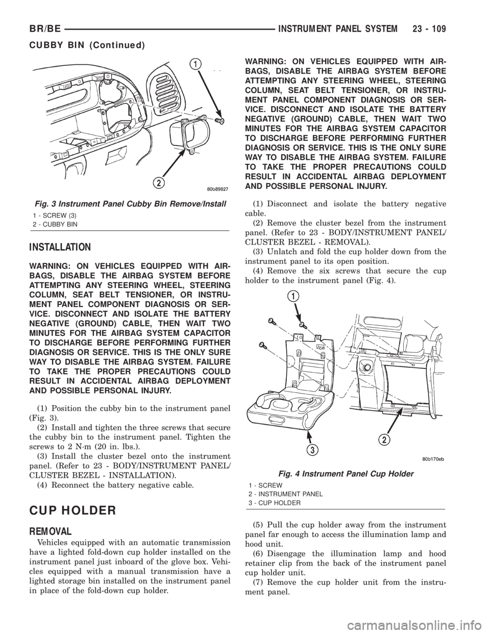
(1) Position the cubby bin to the instrument panel
(Fig. 3).
(2) Install and tighten the three screws that secure
the cubby bin to the instrument panel. Tighten the
screws to 2 N´m (20 in. lbs.).
(3) Install the cluster bezel onto the instrument
panel. (Refer to 23 - BODY/INSTRUMENT PANEL/
CLUSTER BEZEL - INSTALLATION).
(4) Reconnect the battery negative cable.
CUP HOLDER
REMOVAL
Vehicles equipped with an automatic transmission
have a lighted fold-down cup holder installed on the
instrument panel just inboard of the glove box. Vehi-
cles equipped with a manual transmission have a
lighted storage bin installed on the instrument panel
in place of the fold-down cup holder.WARNING: ON VEHICLES EQUIPPED WITH AIR-
BAGS, DISABLE THE AIRBAG SYSTEM BEFORE
ATTEMPTING ANY STEERING WHEEL, STEERING
COLUMN, SEAT BELT TENSIONER, OR INSTRU-
MENT PANEL COMPONENT DIAGNOSIS OR SER-
VICE. DISCONNECT AND ISOLATE THE BATTERY
NEGATIVE (GROUND) CABLE, THEN WAIT TWO
MINUTES FOR THE AIRBAG SYSTEM CAPACITOR
TO DISCHARGE BEFORE PERFORMING FURTHER
DIAGNOSIS OR SERVICE. THIS IS THE ONLY SURE
WAY TO DISABLE THE AIRBAG SYSTEM. FAILURE
TO TAKE THE PROPER PRECAUTIONS COULD
RESULT IN ACCIDENTAL AIRBAG DEPLOYMENT
AND POSSIBLE PERSONAL INJURY.
(1) Disconnect and isolate the battery negative
cable.
(2) Remove the cluster bezel from the instrument
panel. (Refer to 23 - BODY/INSTRUMENT PANEL/
CLUSTER BEZEL - REMOVAL).
(3) Unlatch and fold the cup holder down from the
instrument panel to its open position.
(4) Remove the six screws that secure the cup
holder to the instrument panel (Fig. 4).
(5) Pull the cup holder away from the instrument
panel far enough to access the illumination lamp and
hood unit.
(6) Disengage the illumination lamp and hood
retainer clip from the back of the instrument panel
cup holder unit.
(7) Remove the cup holder unit from the instru-
ment panel.
Fig. 3 Instrument Panel Cubby Bin Remove/Install
1 - SCREW (3)
2 - CUBBY BIN
Fig. 4 Instrument Panel Cup Holder
1 - SCREW
2 - INSTRUMENT PANEL
3 - CUP HOLDER
BR/BEINSTRUMENT PANEL SYSTEM 23 - 109
CUBBY BIN (Continued)
Page 2077 of 2255
INSTALLATION
Vehicles equipped with an automatic transmission
have a lighted fold-down cup holder installed on the
instrument panel just inboard of the glove box. Vehi-
cles equipped with a manual transmission have a
lighted storage bin installed on the instrument panel
in place of the fold-down cup holder.
WARNING: ON VEHICLES EQUIPPED WITH AIR-
BAGS, DISABLE THE AIRBAG SYSTEM BEFORE
ATTEMPTING ANY STEERING WHEEL, STEERING
COLUMN, SEAT BELT TENSIONER, OR INSTRU-
MENT PANEL COMPONENT DIAGNOSIS OR SER-
VICE. DISCONNECT AND ISOLATE THE BATTERY
NEGATIVE (GROUND) CABLE, THEN WAIT TWO
MINUTES FOR THE AIRBAG SYSTEM CAPACITOR
TO DISCHARGE BEFORE PERFORMING FURTHER
DIAGNOSIS OR SERVICE. THIS IS THE ONLY SURE
WAY TO DISABLE THE AIRBAG SYSTEM. FAILURE
TO TAKE THE PROPER PRECAUTIONS COULD
RESULT IN ACCIDENTAL AIRBAG DEPLOYMENT
AND POSSIBLE PERSONAL INJURY.
(1) Position the cup holder unit near the instru-
ment panel.
(2) Engage the illumination lamp and hood
retainer clip to the back of the instrument panel cup
holder unit.
(3) Position the cup holder unit onto the instru-
ment panel (Fig. 4).
(4) Install and tighten the six screws that secure
the cup holder to the instrument panel. Tighten the
screws to 2 N´m (20 in. lbs.).
(5) Reinstall the cluster bezel onto the instrument
panel. (Refer to 23 - BODY/INSTRUMENT PANEL/
CLUSTER BEZEL - INSTALLATION).
(6) Reconnect the battery negative cable.
GLOVE BOX
REMOVAL
REMOVAL
WARNING: ON VEHICLES EQUIPPED WITH AIR-
BAGS, DISABLE THE AIRBAG SYSTEM BEFORE
ATTEMPTING ANY STEERING WHEEL, STEERING
COLUMN, SEAT BELT TENSIONER, OR INSTRU-
MENT PANEL COMPONENT DIAGNOSIS OR SER-
VICE. DISCONNECT AND ISOLATE THE BATTERY
NEGATIVE (GROUND) CABLE, THEN WAIT TWO
MINUTES FOR THE AIRBAG SYSTEM CAPACITOR
TO DISCHARGE BEFORE PERFORMING FURTHER
DIAGNOSIS OR SERVICE. THIS IS THE ONLY SURE
WAY TO DISABLE THE AIRBAG SYSTEM. FAILURETO TAKE THE PROPER PRECAUTIONS COULD
RESULT IN ACCIDENTAL AIRBAG DEPLOYMENT
AND POSSIBLE PERSONAL INJURY.
(1) Disconnect and isolate the battery negative
cable.
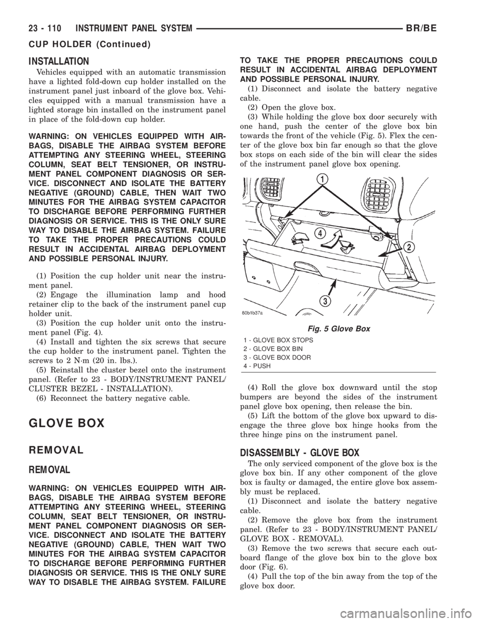
(2) Open the glove box.
(3) While holding the glove box door securely with
one hand, push the center of the glove box bin
towards the front of the vehicle (Fig. 5). Flex the cen-
ter of the glove box bin far enough so that the glove
box stops on each side of the bin will clear the sides
of the instrument panel glove box opening.
(4) Roll the glove box downward until the stop
bumpers are beyond the sides of the instrument
panel glove box opening, then release the bin.
(5) Lift the bottom of the glove box upward to dis-
engage the three glove box hinge hooks from the
three hinge pins on the instrument panel.
DISASSEMBLY - GLOVE BOX
The only serviced component of the glove box is the
glove box bin. If any other component of the glove
box is faulty or damaged, the entire glove box assem-
bly must be replaced.
(1) Disconnect and isolate the battery negative
cable.
(2) Remove the glove box from the instrument
panel. (Refer to 23 - BODY/INSTRUMENT PANEL/
GLOVE BOX - REMOVAL).
(3) Remove the two screws that secure each out-
board flange of the glove box bin to the glove box
door (Fig. 6).
(4) Pull the top of the bin away from the top of the
glove box door.
Fig. 5 Glove Box
1 - GLOVE BOX STOPS
2 - GLOVE BOX BIN
3 - GLOVE BOX DOOR
4 - PUSH
23 - 110 INSTRUMENT PANEL SYSTEMBR/BE
CUP HOLDER (Continued)
Page 2081 of 2255
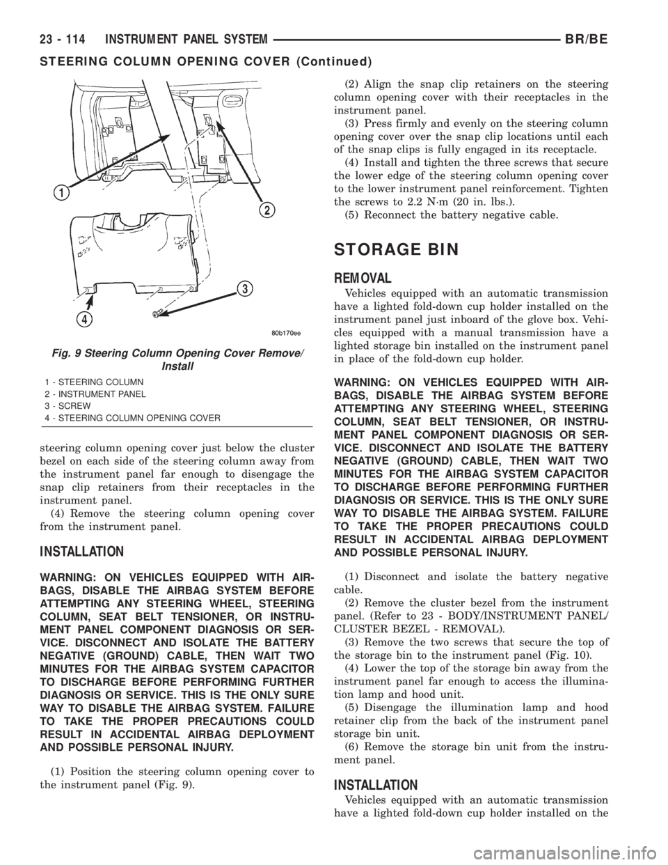
steering column opening cover just below the cluster
bezel on each side of the steering column away from
the instrument panel far enough to disengage the
snap clip retainers from their receptacles in the
instrument panel.
(4) Remove the steering column opening cover
from the instrument panel.
INSTALLATION
WARNING: ON VEHICLES EQUIPPED WITH AIR-
BAGS, DISABLE THE AIRBAG SYSTEM BEFORE
ATTEMPTING ANY STEERING WHEEL, STEERING
COLUMN, SEAT BELT TENSIONER, OR INSTRU-
MENT PANEL COMPONENT DIAGNOSIS OR SER-
VICE. DISCONNECT AND ISOLATE THE BATTERY
NEGATIVE (GROUND) CABLE, THEN WAIT TWO
MINUTES FOR THE AIRBAG SYSTEM CAPACITOR
TO DISCHARGE BEFORE PERFORMING FURTHER
DIAGNOSIS OR SERVICE. THIS IS THE ONLY SURE
WAY TO DISABLE THE AIRBAG SYSTEM. FAILURE
TO TAKE THE PROPER PRECAUTIONS COULD
RESULT IN ACCIDENTAL AIRBAG DEPLOYMENT
AND POSSIBLE PERSONAL INJURY.
(1) Position the steering column opening cover to
the instrument panel (Fig. 9).(2) Align the snap clip retainers on the steering
column opening cover with their receptacles in the
instrument panel.
(3) Press firmly and evenly on the steering column
opening cover over the snap clip locations until each
of the snap clips is fully engaged in its receptacle.
(4) Install and tighten the three screws that secure
the lower edge of the steering column opening cover
to the lower instrument panel reinforcement. Tighten
the screws to 2.2 N´m (20 in. lbs.).
(5) Reconnect the battery negative cable.
STORAGE BIN
REMOVAL
Vehicles equipped with an automatic transmission
have a lighted fold-down cup holder installed on the
instrument panel just inboard of the glove box. Vehi-
cles equipped with a manual transmission have a
lighted storage bin installed on the instrument panel
in place of the fold-down cup holder.
WARNING: ON VEHICLES EQUIPPED WITH AIR-
BAGS, DISABLE THE AIRBAG SYSTEM BEFORE
ATTEMPTING ANY STEERING WHEEL, STEERING
COLUMN, SEAT BELT TENSIONER, OR INSTRU-
MENT PANEL COMPONENT DIAGNOSIS OR SER-
VICE. DISCONNECT AND ISOLATE THE BATTERY
NEGATIVE (GROUND) CABLE, THEN WAIT TWO
MINUTES FOR THE AIRBAG SYSTEM CAPACITOR
TO DISCHARGE BEFORE PERFORMING FURTHER
DIAGNOSIS OR SERVICE. THIS IS THE ONLY SURE
WAY TO DISABLE THE AIRBAG SYSTEM. FAILURE
TO TAKE THE PROPER PRECAUTIONS COULD
RESULT IN ACCIDENTAL AIRBAG DEPLOYMENT
AND POSSIBLE PERSONAL INJURY.
(1) Disconnect and isolate the battery negative
cable.
(2) Remove the cluster bezel from the instrument
panel. (Refer to 23 - BODY/INSTRUMENT PANEL/
CLUSTER BEZEL - REMOVAL).
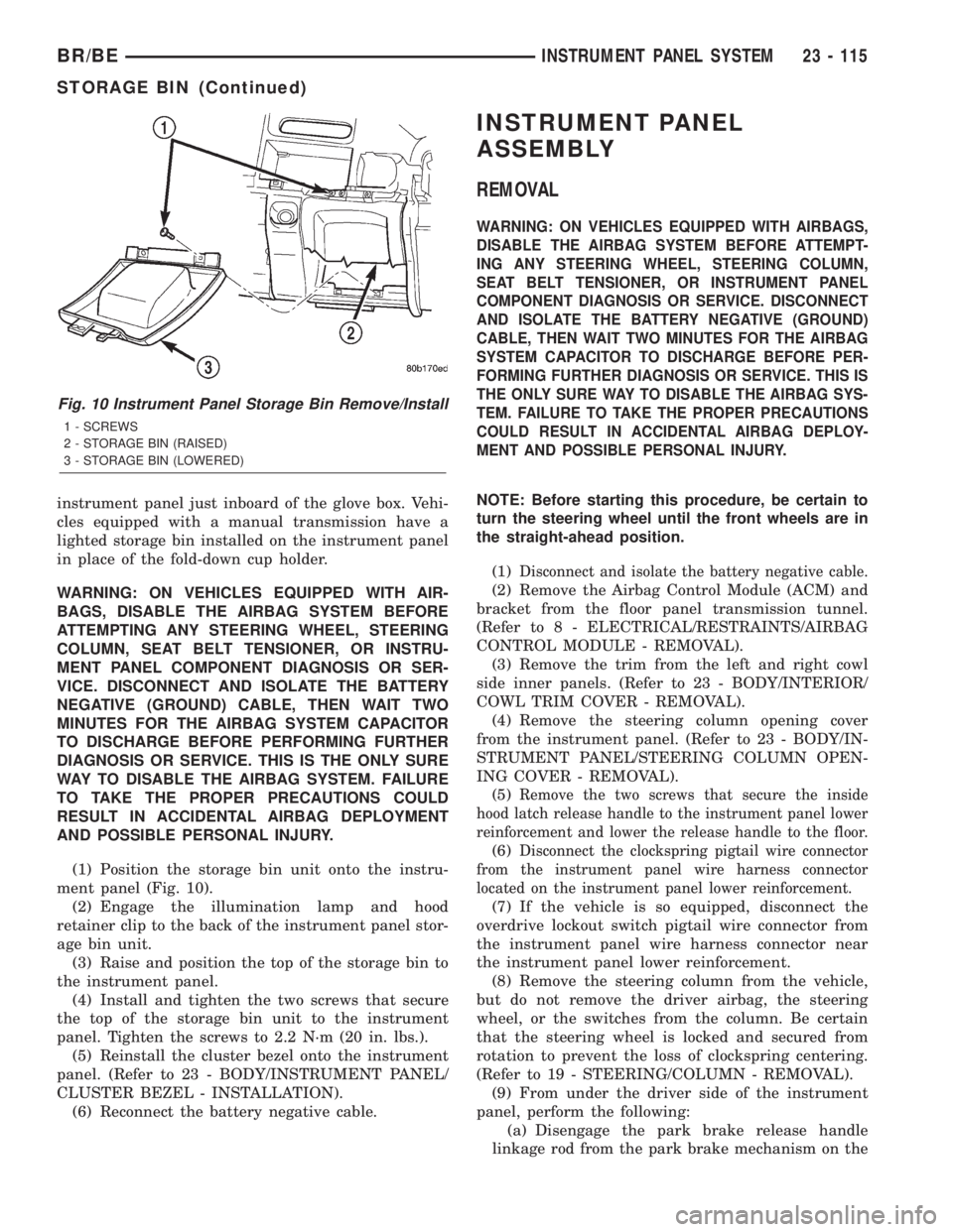
(3) Remove the two screws that secure the top of
the storage bin to the instrument panel (Fig. 10).
(4) Lower the top of the storage bin away from the
instrument panel far enough to access the illumina-
tion lamp and hood unit.
(5) Disengage the illumination lamp and hood
retainer clip from the back of the instrument panel
storage bin unit.
(6) Remove the storage bin unit from the instru-
ment panel.
INSTALLATION
Vehicles equipped with an automatic transmission
have a lighted fold-down cup holder installed on the
Fig. 9 Steering Column Opening Cover Remove/
Install
1 - STEERING COLUMN
2 - INSTRUMENT PANEL
3 - SCREW
4 - STEERING COLUMN OPENING COVER
23 - 114 INSTRUMENT PANEL SYSTEMBR/BE
STEERING COLUMN OPENING COVER (Continued)
Page 2082 of 2255
instrument panel just inboard of the glove box. Vehi-
cles equipped with a manual transmission have a
lighted storage bin installed on the instrument panel
in place of the fold-down cup holder.
WARNING: ON VEHICLES EQUIPPED WITH AIR-
BAGS, DISABLE THE AIRBAG SYSTEM BEFORE
ATTEMPTING ANY STEERING WHEEL, STEERING
COLUMN, SEAT BELT TENSIONER, OR INSTRU-
MENT PANEL COMPONENT DIAGNOSIS OR SER-
VICE. DISCONNECT AND ISOLATE THE BATTERY
NEGATIVE (GROUND) CABLE, THEN WAIT TWO
MINUTES FOR THE AIRBAG SYSTEM CAPACITOR
TO DISCHARGE BEFORE PERFORMING FURTHER
DIAGNOSIS OR SERVICE. THIS IS THE ONLY SURE
WAY TO DISABLE THE AIRBAG SYSTEM. FAILURE
TO TAKE THE PROPER PRECAUTIONS COULD
RESULT IN ACCIDENTAL AIRBAG DEPLOYMENT
AND POSSIBLE PERSONAL INJURY.
(1) Position the storage bin unit onto the instru-
ment panel (Fig. 10).
(2) Engage the illumination lamp and hood
retainer clip to the back of the instrument panel stor-
age bin unit.
(3) Raise and position the top of the storage bin to
the instrument panel.
(4) Install and tighten the two screws that secure
the top of the storage bin unit to the instrument
panel. Tighten the screws to 2.2 N´m (20 in. lbs.).
(5) Reinstall the cluster bezel onto the instrument
panel. (Refer to 23 - BODY/INSTRUMENT PANEL/
CLUSTER BEZEL - INSTALLATION).
(6) Reconnect the battery negative cable.
INSTRUMENT PANEL
ASSEMBLY
REMOVAL
WARNING: ON VEHICLES EQUIPPED WITH AIRBAGS,
DISABLE THE AIRBAG SYSTEM BEFORE ATTEMPT-
ING ANY STEERING WHEEL, STEERING COLUMN,
SEAT BELT TENSIONER, OR INSTRUMENT PANEL
COMPONENT DIAGNOSIS OR SERVICE. DISCONNECT
AND ISOLATE THE BATTERY NEGATIVE (GROUND)
CABLE, THEN WAIT TWO MINUTES FOR THE AIRBAG
SYSTEM CAPACITOR TO DISCHARGE BEFORE PER-
FORMING FURTHER DIAGNOSIS OR SERVICE. THIS IS
THE ONLY SURE WAY TO DISABLE THE AIRBAG SYS-
TEM. FAILURE TO TAKE THE PROPER PRECAUTIONS
COULD RESULT IN ACCIDENTAL AIRBAG DEPLOY-
MENT AND POSSIBLE PERSONAL INJURY.
NOTE: Before starting this procedure, be certain to
turn the steering wheel until the front wheels are in
the straight-ahead position.
(1)
Disconnect and isolate the battery negative cable.
(2) Remove the Airbag Control Module (ACM) and
bracket from the floor panel transmission tunnel.
(Refer to 8 - ELECTRICAL/RESTRAINTS/AIRBAG
CONTROL MODULE - REMOVAL).
(3) Remove the trim from the left and right cowl
side inner panels. (Refer to 23 - BODY/INTERIOR/
COWL TRIM COVER - REMOVAL).
(4) Remove the steering column opening cover
from the instrument panel. (Refer to 23 - BODY/IN-
STRUMENT PANEL/STEERING COLUMN OPEN-
ING COVER - REMOVAL).
(5)
Remove the two screws that secure the inside
hood latch release handle to the instrument panel lower
reinforcement and lower the release handle to the floor.
(6)Disconnect the clockspring pigtail wire connector
from the instrument panel wire harness connector
located on the instrument panel lower reinforcement.
(7) If the vehicle is so equipped, disconnect the
overdrive lockout switch pigtail wire connector from
the instrument panel wire harness connector near
the instrument panel lower reinforcement.
(8) Remove the steering column from the vehicle,
but do not remove the driver airbag, the steering
wheel, or the switches from the column. Be certain
that the steering wheel is locked and secured from
rotation to prevent the loss of clockspring centering.
(Refer to 19 - STEERING/COLUMN - REMOVAL).
(9) From under the driver side of the instrument
panel, perform the following:
(a) Disengage the park brake release handle
linkage rod from the park brake mechanism on the
Fig. 10 Instrument Panel Storage Bin Remove/Install
1 - SCREWS
2 - STORAGE BIN (RAISED)
3 - STORAGE BIN (LOWERED)
BR/BEINSTRUMENT PANEL SYSTEM 23 - 115
STORAGE BIN (Continued)
Page 2084 of 2255
wire harness connectors from the heater-A/C housing
wire harness connectors.
(15) With the aid of an assistant, remove the tem-
porary hook and lift the instrument panel assembly
off of the roll-down bracket screws and remove it
from the vehicle.
INSTALLATION
WARNING: ON VEHICLES EQUIPPED WITH AIRBAGS,
DISABLE THE AIRBAG SYSTEM BEFORE ATTEMPT-
ING ANY STEERING WHEEL, STEERING COLUMN,
SEAT BELT TENSIONER, OR INSTRUMENT PANEL
COMPONENT DIAGNOSIS OR SERVICE. DISCONNECT
AND ISOLATE THE BATTERY NEGATIVE (GROUND)
CABLE, THEN WAIT TWO MINUTES FOR THE AIRBAG
SYSTEM CAPACITOR TO DISCHARGE BEFORE PER-
FORMING FURTHER DIAGNOSIS OR SERVICE. THIS IS
THE ONLY SURE WAY TO DISABLE THE AIRBAG SYS-
TEM. FAILURE TO TAKE THE PROPER PRECAUTIONS
COULD RESULT IN ACCIDENTAL AIRBAG DEPLOY-
MENT AND POSSIBLE PERSONAL INJURY.
(1)With the aid of an assistant, load the instrument
panel assembly onto the roll-down bracket screws on
the cowl side inner panels in the vehicle (Fig. 11).
Install a temporary hook in the center hole on top of the
instrument panel. Secure the other end of the hook to
the center hole in the top of the dash panel. The hook
should support the instrument panel in its rolled down
position about 46 cm (18 inches) from the dash panel.
(2) With the instrument panel supported in the
roll-down position, reconnect the instrument panel
wire harness connectors to the heater-A/C housing
wire harness connectors.
(3) Remove the temporary hook from the instru-
ment panel and roll the instrument panel up to its
installed position against the dash panel.
(4) Install and tighten the five screws that secure
the top of the instrument panel to the top of the dash
panel. Tighten the screws to 3.2 N´m (28 in. lbs.).
(5) Tighten the right and left instrument panel
cowl side roll-down bracket screws. Tighten the
screws to 11.9 N´m (105 in. lbs.).
(6) From under the passenger side of the instru-
ment panel, reconnect the two halves of the radio
antenna coaxial cable connector.
(7) From under the driver side of the instrument
panel, perform the following:
(a) Engage the park brake release handle link-
age rod with the park brake mechanism on the left
cowl side inner panel. (Refer to 5 - BRAKES/PARK-
ING BRAKE/RELEASE - INSTALLATION).
(b) Reconnect the instrument panel wire harness
connector to the park brake switch on the park
brake mechanism.(c) Reconnect the three connectors (one from the
body wire harness, and two from the headlamp and
dash wire harness) to the three connector recepta-
cles located closest to the dash panel on the back of
the Junction Block (JB).
(d)
Reconnect the headlamp and dash wire harness
to instrument panel wire harness bulkhead connector
and tighten the screw in the center of the connector.
Tighten the screw to 3.5 N´m (31 in. lbs.).
(e) Reconnect the instrument panel wire harness
to door wire harness connector located directly
below the instrument panel wire harness to head-
lamp and dash wire harness bulkhead connector.
(f) If the vehicle is equipped with the Infinity
sound system option, reconnect the Infinity wire
harness connector to the instrument panel wire
harness connector that is secured to the outboard
side of the instrument panel wire harness to head-
lamp and dash wire harness bulkhead connector.
(g) Reconnect the instrument panel wire harness
connector to the stop lamp switch.
(h) Reconnect the heater-A/C housing vacuum
harness connector to the heater-A/C control vac-
uum harness connector located near the left end of
the heater-A/C housing.
(8) Reinstall the steering column into the vehicle.
Be certain that the steering wheel was locked and
secured from rotation to prevent the loss of clock-
spring centering. (Refer to 19 - STEERING/COL-
UMN - INSTALLATION).
(9) If the vehicle is so equipped, reconnect the
overdrive lockout switch pigtail wire connector to the
instrument panel wire harness connector near the
instrument panel lower reinforcement.
(10) Reconnect the clockspring pigtail wire connec-
tor to the instrument panel wire harness connector
at the instrument panel lower reinforcement.
(11) Position the inside hood latch release handle
to the instrument panel lower reinforcement.
(12) Install and tighten the two screws that secure
the inside hood latch release handle to the instru-
ment panel lower reinforcement. Tighten the screws
to 2.8 N´m (25 in. lbs.).
(13) Reinstall the steering column opening cover
onto the instrument panel. (Refer to 23 - BODY/IN-
STRUMENT PANEL/STEERING COLUMN OPEN-
ING COVER - INSTALLATION).
(14) Reinstall the trim onto the left and right cowl
side inner panels. (Refer to 23 - BODY/INTERIOR/
COWL TRIM COVER - INSTALLATION).
(15) Reinstall the Airbag Control Module (ACM)
and bracket onto the floor panel transmission tunnel.
(Refer to 8 - ELECTRICAL/RESTRAINTS/AIRBAG
CONTROL MODULE - INSTALLATION).
(16) Reconnect the battery negative cable.
BR/BEINSTRUMENT PANEL SYSTEM 23 - 117
INSTRUMENT PANEL ASSEMBLY (Continued)
Page 2250 of 2255
TRANSMITTER BATTERIES - STANDARD
PROCEDURE, REMOTE KEYLESS
ENTRY..............................8N-8
TRANSMITTER PROGRAMMING -
STANDARD PROCEDURE, RKE...........8N-8
TRAY - DESCRIPTION, BATTERY.........8F-23
TRAY - INSTALLATION, BATTERY........8F-24
TRAY - INSTALLATION, REAR FLOOR
STOWAGE.........................23-121
TRAY - OPERATION, BATTERY..........8F-23
TRAY - REMOVAL, BATTERY............8F-23
TRAY - REMOVAL, REAR FLOOR
STOWAGE.........................23-121
TREAD WEAR INDICATORS - DIAGNOSIS
AND TESTING........................22-8
TRIM - INSTALLATION, A-PILLAR.......23-119
TRIM - INSTALLATION, B-PILLAR.......23-120
TRIM - INSTALLATION, C-PILLAR.......23-128
TRIM - INSTALLATION, DOOR SILL.....23-121
TRIM - INSTALLATION, GLOVE BOX
OPENING UPPER....................23-112
TRIM - INSTALLATION, REAR CLOSURE
PANEL............................23-121
TRIM - REMOVAL, A-PILLAR..........23-119
TRIM - REMOVAL, B-PILLAR..........23-120
TRIM - REMOVAL, C-PILLAR..........23-128
TRIM - REMOVAL, DOOR SILL.........23-121
TRIM - REMOVAL, GLOVE BOX OPENING
UPPER............................23-112
TRIM - REMOVAL, REAR CLOSURE
PANEL............................23-120
TRIM COVER - INSTALLATION, COWL . . . 23-120
TRIM COVER - REMOVAL, COWL.......23-119
TRIM PANEL - INSTALLATION......23-75,23-84
TRIM PANEL - INSTALLATION, QUARTER . 23-128
TRIM PANEL - REMOVAL.........23-75,23-83
TRIM PANEL - REMOVAL, QUARTER....23-128
TRIP DEFINITION - DESCRIPTION........25-19
TROUBLE CODES - DESCRIPTION,
DIAGNOSTIC.........................25-2
TUBE - DESCRIPTION, A/C ORIFICE......24-54
TUBE - DIAGNOSIS AND TESTING, FIXED
ORIFICE............................24-54
TUBE - INSTALLATION, A/C ORIFICE......24-54
TUBE - OPERATION, A/C ORIFICE........24-54
TUBE - REMOVAL, A/C ORIFICE.........24-54
TUBES - WITH RADIATOR IN-TANK
TRANSMISSION OIL COOLER -
STANDARD PROCEDURE, FLUSHING
COOLERS...................7-78,7-82,7-84
TUBES - WITHOUT RADIATOR IN-TANK
TRANSMISSION OIL COOLER -
STANDARD PROCEDURE, FLUSHING
COOLERS...................7-79,7-82,7-85
TURBOCHARGER - CLEANING..........11-16
TURBOCHARGER - DESCRIPTION........11-14
TURBOCHARGER - INSPECTION.........11-16
TURBOCHARGER - INSTALLATION.......11-17
TURBOCHARGER - OPERATION.........11-14
TURBOCHARGER - REMOVAL...........11-15
TURBOCHARGER BOOST PRESSURE -
DIAGNOSIS AND TESTING.............11-13
TURN SIGNAL & HAZARD WARNING
SYSTEM - DESCRIPTION
...............8L-2
TURN SIGNAL & HAZARD WARNING
SYSTEM - DIAGNOSIS AND TESTING
......8L-3
TURN SIGNAL & HAZARD WARNING
SYSTEM - OPERATION
.................8L-2
TURN SIGNAL CANCEL CAM -
DESCRIPTION
.......................8L-31
TURN SIGNAL CANCEL CAM -
OPERATION
.........................8L-31
TURN SIGNAL INDICATOR -
DESCRIPTION
.......................8J-32
TURN SIGNAL INDICATOR - DIAGNOSIS
AND TESTING
.......................8J-32
TURN SIGNAL INDICATOR - OPERATION
. . 8J-32
TURNING LOOP ADJUSTER -
INSTALLATION, SEAT BELT
.............8O-29
TURNING LOOP ADJUSTER - REMOVAL,
SEAT BELT
.........................8O-29
TURNING LOOP HGT ADJUSTER KNOB -
INSTALLATION
......................8O-30
TURNING LOOP HGT ADJUSTER KNOB -
REMOVAL
..........................8O-30
TWEETER SPEAKER - INSTALLATION,
A-PILLAR
...........................8A-19TWEETER SPEAKER - REMOVAL,
A-PILLAR...........................8A-18
UNDERHOOD LAMP - INSTALLATION.....8L-32
UNDERHOOD LAMP - REMOVAL.........8L-31
UNDERHOOD LAMP UNIT -
INSTALLATION.......................8L-32
UNDERHOOD LAMP UNIT - REMOVAL....8L-32
UNIVERSAL JOINTS - ASSEMBLY,
DOUBLE CARDAN.....................3-11
UNIVERSAL JOINTS - ASSEMBLY,
SINGLE CARDAN.......................3-9
UNIVERSAL JOINTS - DISASSEMBLY,
DOUBLE CARDAN.....................3-10
UNIVERSAL JOINTS - DISASSEMBLY,
SINGLE CARDAN.......................3-8
UNIVERSAL JOINTS - INSTALLATION,
SINGLE CARDAN......................3-35
UNIVERSAL JOINTS - REMOVAL, SINGLE
CARDAN............................3-34
UP/DOWN - ADJUSTMENT, FRONT DOOR . 23-70
UPPER - INSTALLATION, LATCH.........23-81
UPPER - INSTALLATION, LATCH
STRIKER...........................23-82
UPPER - REMOVAL, LATCH............23-81
UPPER - REMOVAL, LATCH STRIKER.....23-82
UPPER BALL JOINT - DIAGNOSIS AND
TESTING............................2-12
UPPER CONTROL ARM - INSTALLATION . . . 2-13,
2-19
UPPER CONTROL ARM - REMOVAL . . . 2-13,2-19
UPSHIFT INDICATOR - DESCRIPTION......8J-32
UPSHIFT INDICATOR - OPERATION.......8J-33
USAGE - DESCRIPTION, FASTENER.....Intro.-9
USE WIRING DIAGRAMS -
DESCRIPTION, HOW TO.............8W-01-1
USING MIDTRONICS ELECTRICAL
TESTER - STANDARD PROCEDURE.......8F-15
V-10 - DESCRIPTION, 8.0L..............8I-2
V-10 - OPERATION, 8.0L................8I-2
V-10 ENGINE - IGNITION COIL
RESISTANCE, 8.0L.....................8I-4
V-10 ENGINE - SPARK PLUG CABLE
ORDER, 8.0L.........................8I-3
V-8 - OPERATION......................8I-2
V-8 ENGINES - DESCRIPTION...........25-35
V-8 ENGINES - ENGINE FIRING ORDER,
5.9L................................8I-3
V-8 ENGINES - OPERATION............25-35
VACUUM CHECK VALVE - DESCRIPTION . . 24-28
VACUUM CHECK VALVE - INSTALLATION . . 24-29
VACUUM CHECK VALVE - OPERATION....24-28
VACUUM CHECK VALVE - REMOVAL......24-29
VACUUM LINES - DESCRIPTION.........25-37
VACUUM MOTOR - ASSEMBLY, AXLE......3-34
VACUUM MOTOR - DESCRIPTION, AXLE . . . 3-31
VACUUM MOTOR - DIAGNOSIS AND
TESTING............................3-32
VACUUM MOTOR - DISASSEMBLY, AXLE . . . 3-34
VACUUM MOTOR - INSTALLATION, AXLE . . . 3-34
VACUUM MOTOR - OPERATION, AXLE.....3-31
VACUUM MOTOR - REMOVAL, AXLE......3-34
VACUUM PUMP - 5.9L DIESEL -
DESCRIPTION........................7-33
VACUUM PUMP - 5.9L DIESEL -
INSTALLATION........................7-36
VACUUM PUMP - 5.9L DIESEL -
OPERATION
..........................7-34
VACUUM PUMP - 5.9L DIESEL -
REMOVAL
...........................7-34
VACUUM PUMP OUTPUT - DIAGNOSIS
AND TESTING
........................7-34
VACUUM RESERVOIR - DESCRIPTION
....8P-14
VACUUM RESERVOIR - INSTALLATION
. . . 8P-15
VACUUM RESERVOIR - REMOVAL
.......8P-14
VACUUM SUPPLY TEST - DIAGNOSIS
AND TESTING
........................8P-3
VACUUM SYSTEM - DIAGNOSIS AND
TESTING
...........................24-10
VACUUM TEST - DIAGNOSIS AND
TESTING, FUEL SYSTEM AIR LEAK
.......14-57
VALVE - 5.9L - DIAGNOSIS AND
TESTING, PCV
.......................25-36
VALVE - CLEANING, OIL PRESSURE
RELIEF
.............................9-180
VALVE - DESCRIPTION, COMBINATION
......5-8
VALVE - DESCRIPTION, FUEL TANK
CHECK
.............................14-21VALVE - DESCRIPTION, HIGH PRESSURE
RELIEF.............................24-46
VALVE - DESCRIPTION, ONE WAY CHECK . 25-31
VALVE - DESCRIPTION, OVERFLOW......14-87
VALVE - DESCRIPTION, TORQUE
CONVERTER DRAINBACK.......21-217,21-390
VALVE - DESCRIPTION, VACUUM CHECK . . 24-28
VALVE - DIAGNOSIS AND TESTING,
COMBINATION.........................5-9
VALVE - DIAGNOSIS AND TESTING,
ONE-WAY CHECK.....................25-31
VALVE - DIAGNOSIS AND TESTING,
OVERFLOW.........................14-87
VALVE - INSPECTION, OIL PRESSURE
RELIEF.............................9-180
VALVE - INSTALLATION, COMBINATION.....5-9
VALVE - INSTALLATION, FUEL TANK
CHECK.............................14-23
VALVE - INSTALLATION, OIL PRESSURE
RELIEF.............................9-180
VALVE - INSTALLATION, ONE WAY
CHECK.............................25-31
VALVE - INSTALLATION, OVERFLOW.....14-88
VALVE - INSTALLATION, SPOOL.........19-28
VALVE - INSTALLATION, VACUUM CHECK . 24-29
VALVE - OPERATION, COMBINATION.......5-9
VALVE - OPERATION, HIGH PRESSURE
RELIEF.............................24-47
VALVE - OPERATION, ONE WAY CHECK . . . 25-31
VALVE - OPERATION, OVERFLOW........14-87
VALVE - OPERATION, TORQUE
CONVERTER DRAINBACK.......21-217,21-390
VALVE - OPERATION, VACUUM CHECK....24-28
VALVE - REMOVAL, COMBINATION.........5-9
VALVE - REMOVAL, FUEL TANK CHECK . . . 14-22
VALVE - REMOVAL, OIL PRESSURE
RELIEF.............................9-180
VALVE - REMOVAL, ONE WAY CHECK....25-31
VALVE - REMOVAL, OVERFLOW.........14-88
VALVE - REMOVAL, SPOOL.............19-26
VALVE - REMOVAL, VACUUM CHECK.....24-29
VALVE - STANDARD PROCEDURE,
TORQUE CONVERTER DRAINBACK.....21-217,
21-390
VALVE BODY - ADJUSTMENTS . . . 21-257,21-428
VALVE BODY - ASSEMBLY......21-248,21-420
VALVE BODY - CLEANING.......21-244,21-418
VALVE BODY - DESCRIPTION....21-218,21-391
VALVE BODY - DISASSEMBLY....21-237,21-409
VALVE BODY - INSPECTION.....21-244,21-419
VALVE BODY - INSTALLATION....21-256,21-428
VALVE BODY - OPERATION......21-223,21-394
VALVE BODY - REMOVAL.......21-236,21-407
VALVE CABLE - ADJUSTMENTS,
TRANSMISSION THROTTLE.....21-210,21-382
VALVE CABLE - DESCRIPTION,
THROTTLE...................21-209,21-381
VALVE LASH ADJUSTMENT AND
VERIFICATION - STANDARD
PROCEDURE........................9-141
VALVE SERVICE, STANDARD
PROCEDURE.........................9-80
VALVE SPRINGS - INSTALLATION,
VALVES .............................9-84
VALVE SPRINGS - REMOVAL, VALVES.....9-82
VALVE STEM SEAL - INSTALLATION.......9-83
VALVE STEM SEALS - REMOVAL.........9-82
VALVES & SEATS - CLEANING,
INTAKE/EXHAUST.....................9-26
VALVES & SEATS - DESCRIPTION,
INTAKE/EXHAUST............9-138,9-23,9-80
VALVES & SEATS - INSPECTION,
INTAKE/EXHAUST.....................9-26
VALVES & SEATS - INSTALLATION,
INTAKE/EXHAUST.....................9-26
VALVES & SEATS - REMOVAL,
INTAKE/EXHAUST.....................9-25
VALVES AND VALVE SPRINGS -
INSTALLATION........................9-84
VALVES AND VALVE SPRINGS -
REMOVAL...........................9-82
VALVES, GUIDES AND SPRINGS -
STANDARD PROCEDURE
................9-23
VALVES,GUIDES AND SPRINGS -
STANDARD PROCEDURE
...............9-138
VANITY LAMP - INSTALLATION
.........8L-37
VANITY LAMP - REMOVAL
.............8L-37
VAPOR CANISTER - DESCRIPTION
.......25-37
BR/BEINDEX 33
Description Group-Page Description Group-Page Description Group-Page