2002 DODGE RAM sensor
[x] Cancel search: sensorPage 1406 of 2255
REMOVAL - DIESEL
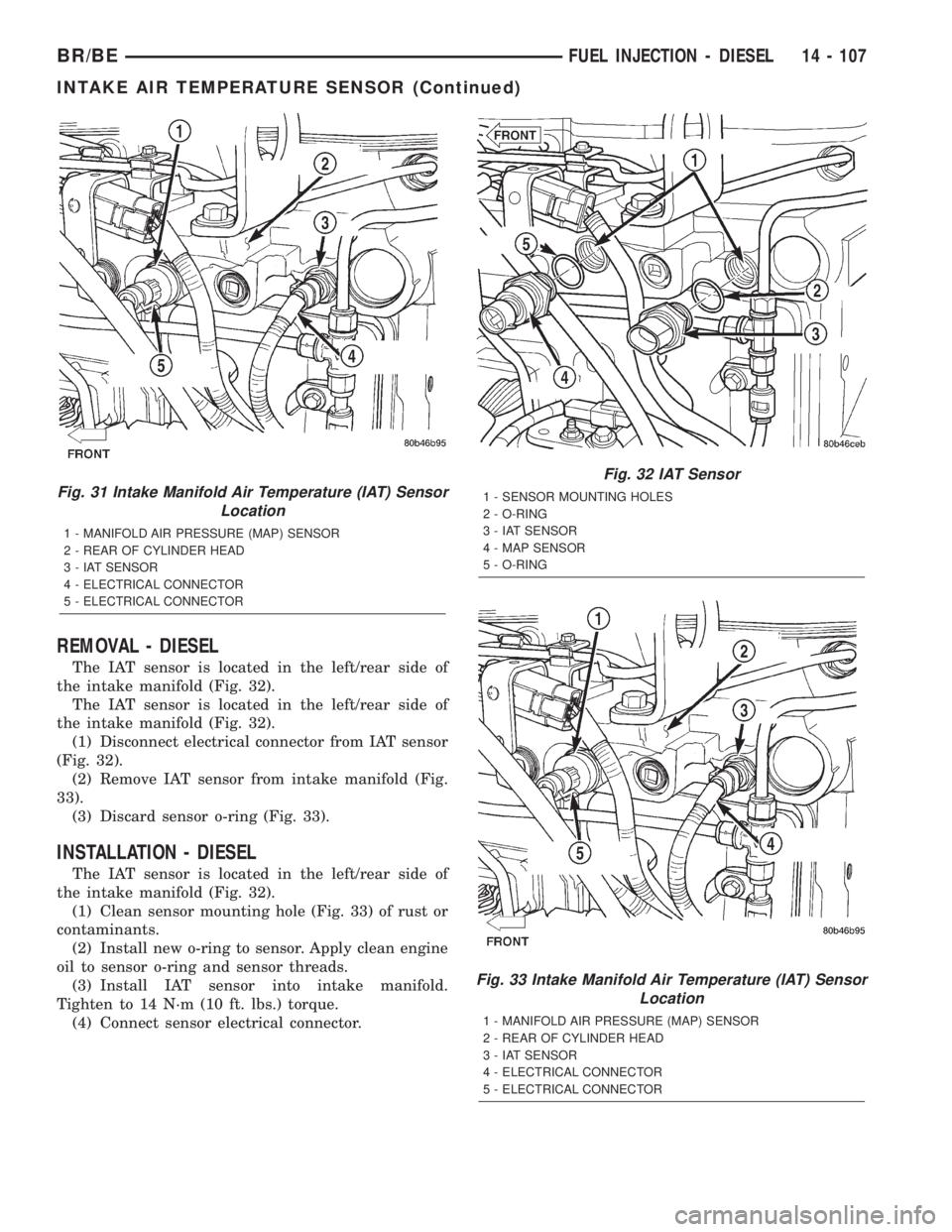
The IAT sensor is located in the left/rear side of
the intake manifold (Fig. 32).
The IAT sensor is located in the left/rear side of
the intake manifold (Fig. 32).
(1) Disconnect electrical connector from IAT sensor
(Fig. 32).
(2) Remove IAT sensor from intake manifold (Fig.
33).
(3) Discard sensor o-ring (Fig. 33).
INSTALLATION - DIESEL
The IAT sensor is located in the left/rear side of
the intake manifold (Fig. 32).
(1) Clean sensor mounting hole (Fig. 33) of rust or
contaminants.
(2) Install new o-ring to sensor. Apply clean engine
oil to sensor o-ring and sensor threads.
(3) Install IAT sensor into intake manifold.
Tighten to 14 N´m (10 ft. lbs.) torque.
(4) Connect sensor electrical connector.
Fig. 31 Intake Manifold Air Temperature (IAT) Sensor
Location
1 - MANIFOLD AIR PRESSURE (MAP) SENSOR
2 - REAR OF CYLINDER HEAD
3 - IAT SENSOR
4 - ELECTRICAL CONNECTOR
5 - ELECTRICAL CONNECTOR
Fig. 32 IAT Sensor
1 - SENSOR MOUNTING HOLES
2 - O-RING
3 - IAT SENSOR
4 - MAP SENSOR
5 - O-RING
Fig. 33 Intake Manifold Air Temperature (IAT) Sensor
Location
1 - MANIFOLD AIR PRESSURE (MAP) SENSOR
2 - REAR OF CYLINDER HEAD
3 - IAT SENSOR
4 - ELECTRICAL CONNECTOR
5 - ELECTRICAL CONNECTOR
BR/BEFUEL INJECTION - DIESEL 14 - 107
INTAKE AIR TEMPERATURE SENSOR (Continued)
Page 1407 of 2255
MAP SENSOR
DESCRIPTION - DIESEL
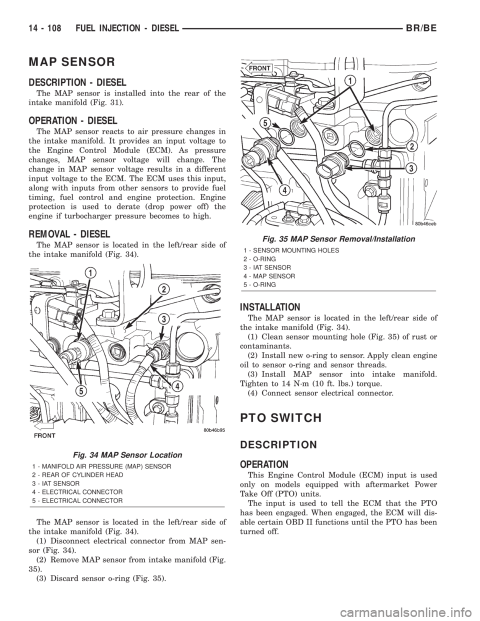
The MAP sensor is installed into the rear of the
intake manifold (Fig. 31).
OPERATION - DIESEL
The MAP sensor reacts to air pressure changes in
the intake manifold. It provides an input voltage to
the Engine Control Module (ECM). As pressure
changes, MAP sensor voltage will change. The
change in MAP sensor voltage results in a different
input voltage to the ECM. The ECM uses this input,
along with inputs from other sensors to provide fuel
timing, fuel control and engine protection. Engine
protection is used to derate (drop power off) the
engine if turbocharger pressure becomes to high.
REMOVAL - DIESEL
The MAP sensor is located in the left/rear side of
the intake manifold (Fig. 34).
The MAP sensor is located in the left/rear side of
the intake manifold (Fig. 34).
(1) Disconnect electrical connector from MAP sen-
sor (Fig. 34).
(2) Remove MAP sensor from intake manifold (Fig.
35).
(3) Discard sensor o-ring (Fig. 35).
INSTALLATION
The MAP sensor is located in the left/rear side of
the intake manifold (Fig. 34).
(1) Clean sensor mounting hole (Fig. 35) of rust or
contaminants.
(2) Install new o-ring to sensor. Apply clean engine
oil to sensor o-ring and sensor threads.
(3) Install MAP sensor into intake manifold.
Tighten to 14 N´m (10 ft. lbs.) torque.
(4) Connect sensor electrical connector.
PTO SWITCH
DESCRIPTION
OPERATION
This Engine Control Module (ECM) input is used
only on models equipped with aftermarket Power
Take Off (PTO) units.
The input is used to tell the ECM that the PTO
has been engaged. When engaged, the ECM will dis-
able certain OBD II functions until the PTO has been
turned off.
Fig. 34 MAP Sensor Location
1 - MANIFOLD AIR PRESSURE (MAP) SENSOR
2 - REAR OF CYLINDER HEAD
3 - IAT SENSOR
4 - ELECTRICAL CONNECTOR
5 - ELECTRICAL CONNECTOR
Fig. 35 MAP Sensor Removal/Installation
1 - SENSOR MOUNTING HOLES
2 - O-RING
3 - IAT SENSOR
4 - MAP SENSOR
5 - O-RING
14 - 108 FUEL INJECTION - DIESELBR/BE
Page 1457 of 2255
HARD SHIFTING
Hard shifting is usually caused by a low lubricant
level, improper or contaminated lubricants. The con-
sequence of using non-recommended lubricants is
noise, excessive wear, internal bind and hard shift-
ing. Substantial lubricant leaks can result in gear,
shift rail, synchro, and bearing damage. If a leak
goes undetected for an extended period, the first indi-
cations of component damage are usually hard shift-
ing and noise.
Component damage, incorrect clutch adjustment or
damaged clutch pressure plate or disc are additional
probable causes of increased shift effort. Incorrect
adjustment or a worn/damaged pressure plate or disc
can cause incorrect release. If clutch problem is
advanced, gear clash during shifts can result. Worn
or damaged synchro rings can cause gear clash when
shifting into any forward gear. In some new or
rebuilt transmissions, new synchro rings may tend to
stick slightly causing hard or noisy shifts. In most
cases this condition will decline as the rings wear-in.
TRANSMISSION NOISE
Most manual transmissions make some noise dur-
ing normal operation. Rotating gears generate a mild
whine that is audible, but generally only at extreme
speeds. Severe highly audible transmission noise is
generally the initial indicator of a lubricant problem.
Insufficient, improper or contaminated lubricant
will promote rapid wear of gears, synchros, shift
rails, forks and bearings. The overheating caused by
a lubricant problem, can also lead to gear breakage.
REMOVAL
(1) Disconnect battery negative cable.
(2) Shift transmission into Neutral.
(3) Remove shift boot screws from floorpan and
slide boot upward on the shift lever.
(4) Remove shift lever extension from shift tower
and lever assembly.
(5) Remove shift tower bolts holding tower to iso-
lator plate and transmission shift cover.
(6) Remove shift tower and isolator plate from
transmission shift cover.
(7) Raise and support vehicle.
(8) Remove skid plate, if equipped.
(9) Mark propeller shaft and axle yokes for instal-
lation reference and remove shaft/shafts.
(10) Remove exhaust system Y-pipe.
(11) Disconnect speed sensor and backup light
switch connectors.
(12) Support engine with safety stand and a wood
block.
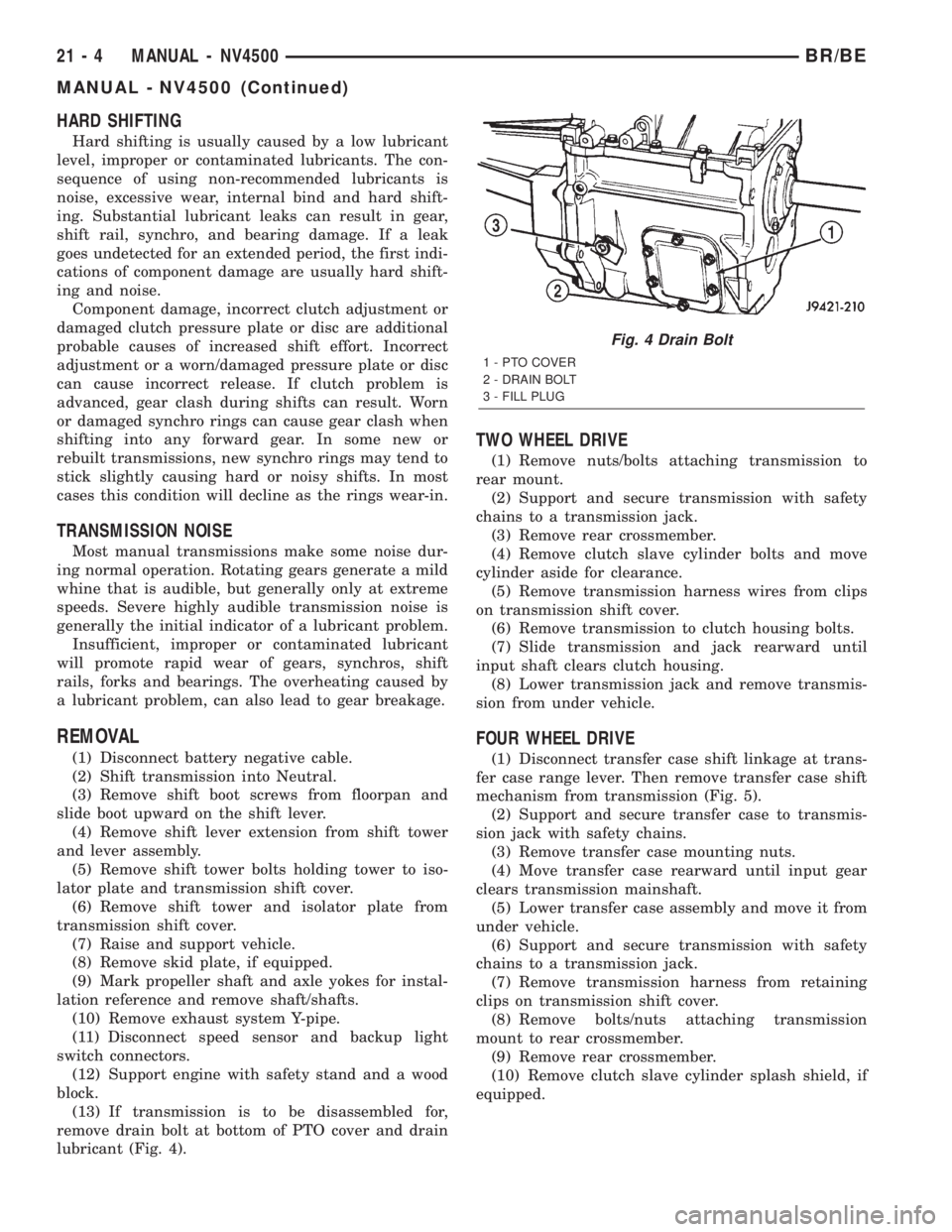
(13) If transmission is to be disassembled for,
remove drain bolt at bottom of PTO cover and drain
lubricant (Fig. 4).
TWO WHEEL DRIVE
(1) Remove nuts/bolts attaching transmission to
rear mount.
(2) Support and secure transmission with safety
chains to a transmission jack.
(3) Remove rear crossmember.
(4) Remove clutch slave cylinder bolts and move
cylinder aside for clearance.
(5) Remove transmission harness wires from clips
on transmission shift cover.
(6) Remove transmission to clutch housing bolts.
(7) Slide transmission and jack rearward until
input shaft clears clutch housing.
(8) Lower transmission jack and remove transmis-
sion from under vehicle.
FOUR WHEEL DRIVE
(1) Disconnect transfer case shift linkage at trans-
fer case range lever. Then remove transfer case shift
mechanism from transmission (Fig. 5).
(2) Support and secure transfer case to transmis-
sion jack with safety chains.
(3) Remove transfer case mounting nuts.
(4) Move transfer case rearward until input gear
clears transmission mainshaft.
(5) Lower transfer case assembly and move it from
under vehicle.
(6) Support and secure transmission with safety
chains to a transmission jack.
(7) Remove transmission harness from retaining
clips on transmission shift cover.
(8) Remove bolts/nuts attaching transmission
mount to rear crossmember.
(9) Remove rear crossmember.
(10) Remove clutch slave cylinder splash shield, if
equipped.
Fig. 4 Drain Bolt
1 - PTO COVER
2 - DRAIN BOLT
3 - FILL PLUG
21 - 4 MANUAL - NV4500BR/BE
MANUAL - NV4500 (Continued)
Page 1490 of 2255

INSTALLATION
NOTE: If a new transmission is being installed, use
all components supplied with the new transmission.
For example, if a new shift tower is supplied with
the new transmission, do not re-use the original
shift tower.
(1) Apply light coat of Mopar high temperature
bearing grease or equivalent to contact surfaces of
the following components:
²input shaft splines.
²release bearing slide surface of front retainer.
²release bearing bore.
²release fork.
²release fork ball stud.
²propeller shaft slip yoke.
(2) Apply sealer to threads of bottom PTO cover
bolt and install bolt in case.
(3) Mount transmission on jack and position trans-
mission under vehicle.
(4) Raise transmission until input shaft is centered
in release bearing and clutch disc hub.
(5) Move transmission forward and start input
shaft in release bearing, clutch disc and pilot bush-
ing.
(6) Work transmission forward until seated against
clutch housing. Do not allow transmission to remain
unsupported after input shaft has entered clutch
disc.
(7) Install and tighten transmission-to-clutch hous-
ing bolts to 108 N´m (80 ft. lbs.).
(8) Install transmission mount on transmission or
rear crossmember.
(9) Install rear crossmember.
(10) Remove transmission jack and engine support
fixture.
(11) Position transmission harness wires in clips
on shift cover.
(12) Install clutch slave cylinder and install slave
cylinder shield, if equipped.
(13) Connect speed sensor and backup light switch
wires.
TWO WHEEL DRIVE
(1) Fill transmission with recommended lubricant.
Correct fill level is bottom edge of fill plug hole.
(2) Align and install propeller shaft.
(3) Lower vehicle.
(4) Clean the mating surfaces of shift tower, isola-
tor plate and shift cover with suitable wax and
grease remover.
(5) Apply Mopar Gasket Maker or equivalent to
the sealing surface of the shift cover. Do not over
apply sealant.(6) Install the isolator plate onto the shift cover,
metal side down.
(7) Install the shift tower onto the isolator plate.
No sealant is necessary between the shift tower and
the isolator plate.
(8) Verify that the shift tower, isolator plate and
the shift tower bushings are properly aligned.
(9) Install the bolts to hold the shift tower to the
isolator plate and the shift cover. Tighten the shift
tower bolts to 10.2±11.25 N´m (7.5±8.3 ft. lbs.).
(10) Install the shift lever extension onto the shift
tower and lever assembly.
(11) Install shift boot and bezel.
(12) Connect battery negative cable.
FOUR WHEEL DRIVE
(1) Install transfer case shift mechanism on trans-
mission.
(2) Install transfer case on transmission jack.
Secure transfer case to jack with safety chains.
(3) Raise jack and align transfer case input gear
with transmission mainshaft.
(4) Move transfer case forward and seat it on
adapter.
(5) Install and tighten transfer case attaching
nuts. Tighten nuts to 41-47 N´m (30-35 ft. lbs.) if
case has 3/8 studs or 30-41 N´m (22-30 ft. lbs.) if case
has 5/16 studs.
(6) Install transfer case shift mechanism to side of
transfer case.
(7) Connect transfer case shift lever to range lever
on transfer case.
(8) Align and connect propeller shafts.
(9) Fill transmission with required lubricant.
Check lubricant level in transfer case and add lubri-
cant if necessary.
(10) Install transfer case skid plate, if equipped
and crossmember. Tighten attaching bolts/nuts to 41
N´m (30 ft. lbs.).
(11) Install exhaust system components.
(12) Lower vehicle.
(13) Clean the mating surfaces of shift tower, iso-
lator plate and shift cover with suitable wax and
grease remover.
(14) Apply Mopar Gasket Maker or equivalent to
the sealing surface of the shift cover. Do not over
apply sealant.
(15) Install the isolator plate onto the shift cover,
metal side down.
(16) Install the shift tower onto the isolator plate.
No sealant is necessary between the shift tower and
the isolator plate.
(17) Verify that the shift tower, isolator plate and
the shift tower bushings are properly aligned.
BR/BEMANUAL - NV4500 21 - 37
MANUAL - NV4500 (Continued)
Page 1541 of 2255
OVERDRIVE UNIT
REMOVAL............................173
DISASSEMBLY........................173
CLEANING...........................179
INSPECTION.........................180
ASSEMBLY...........................180
INSTALLATION........................189
OVERDRIVE SWITCH
DESCRIPTION........................190
OPERATION..........................190
DIAGNOSIS AND TESTING - OVERDRIVE
ELECTRICAL CONTROLS..............191
REMOVAL............................191
INSTALLATION........................191
OVERRUNNING CLUTCH CAM/OVERDRIVE
PISTON RETAINER
DESCRIPTION........................192
OPERATION..........................192
DISASSEMBLY........................192
CLEANING...........................192
INSPECTION.........................193
ASSEMBLY...........................193
PARK/NEUTRAL POSITION SWITCH
DIAGNOSIS AND TESTING - PARK/NEUTRAL
POSITION SWITCH...................195
REMOVAL............................195
INSTALLATION........................195
PISTONS
DESCRIPTION........................195
OPERATION..........................196
PLANETARY GEARTRAIN/OUTPUT SHAFT
DESCRIPTION........................197
OPERATION..........................197
DISASSEMBLY........................198
INSPECTION.........................199
ASSEMBLY...........................199
REAR CLUTCH
DESCRIPTION........................203
OPERATION..........................203
DISASSEMBLY........................204
CLEANING...........................204
INSPECTION.........................204
ASSEMBLY...........................205
REAR SERVO
DESCRIPTION........................207OPERATION..........................207
DISASSEMBLY........................207
CLEANING...........................207
ASSEMBLY...........................207
SHIFT MECHANISM
DESCRIPTION........................208
OPERATION..........................208
ADJUSTMENTS
ADJUSTMENT.......................208
SOLENOID
DESCRIPTION........................208
OPERATION..........................209
SPEED SENSOR
DESCRIPTION........................209
OPERATION..........................209
THROTTLE VALVE CABLE
DESCRIPTION........................209
ADJUSTMENTS - TRANSMISSION THROTTLE
VALVE CABLE.......................210
TORQUE CONVERTER
DESCRIPTION........................212
OPERATION..........................215
REMOVAL............................216
INSTALLATION........................217
TORQUE CONVERTER DRAINBACK VALVE
DESCRIPTION........................217
OPERATION..........................217
STANDARD PROCEDURE - TORQUE
CONVERTER DRAINBACK VALVE........217
TRANSMISSION TEMPERATURE SENSOR
DESCRIPTION........................218
OPERATION..........................218
VALVE BODY
DESCRIPTION........................218
OPERATION..........................223
REMOVAL............................236
DISASSEMBLY........................237
CLEANING...........................244
INSPECTION.........................244
ASSEMBLY...........................248
INSTALLATION........................256
ADJUSTMENTS - VALVE BODY...........257
21 - 88 AUTOMATIC TRANSMISSION - 46REBR/BE
Page 1549 of 2255
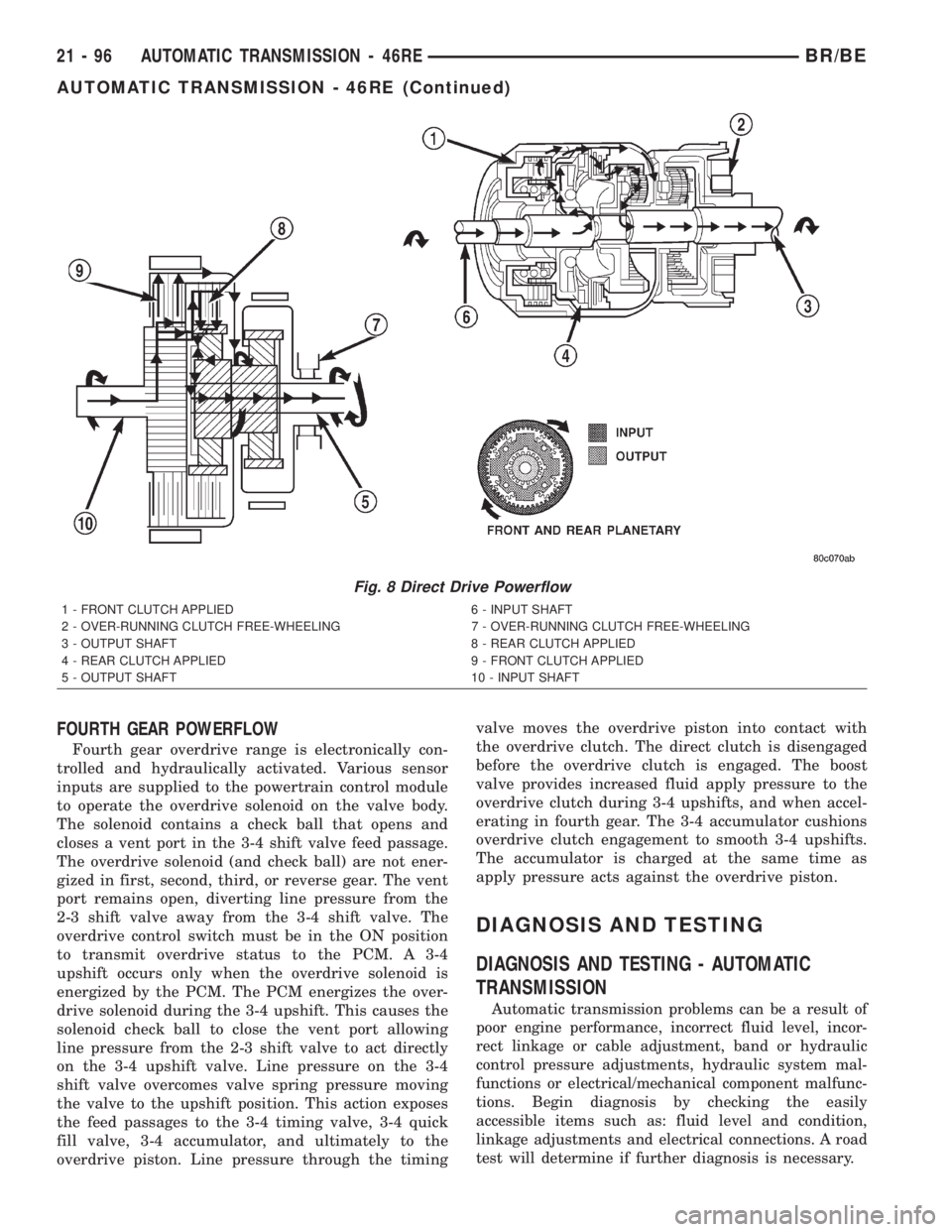
FOURTH GEAR POWERFLOW
Fourth gear overdrive range is electronically con-
trolled and hydraulically activated. Various sensor
inputs are supplied to the powertrain control module
to operate the overdrive solenoid on the valve body.
The solenoid contains a check ball that opens and
closes a vent port in the 3-4 shift valve feed passage.
The overdrive solenoid (and check ball) are not ener-
gized in first, second, third, or reverse gear. The vent
port remains open, diverting line pressure from the
2-3 shift valve away from the 3-4 shift valve. The
overdrive control switch must be in the ON position
to transmit overdrive status to the PCM. A 3-4
upshift occurs only when the overdrive solenoid is
energized by the PCM. The PCM energizes the over-
drive solenoid during the 3-4 upshift. This causes the
solenoid check ball to close the vent port allowing
line pressure from the 2-3 shift valve to act directly
on the 3-4 upshift valve. Line pressure on the 3-4
shift valve overcomes valve spring pressure moving
the valve to the upshift position. This action exposes
the feed passages to the 3-4 timing valve, 3-4 quick
fill valve, 3-4 accumulator, and ultimately to the
overdrive piston. Line pressure through the timingvalve moves the overdrive piston into contact with
the overdrive clutch. The direct clutch is disengaged
before the overdrive clutch is engaged. The boost
valve provides increased fluid apply pressure to the
overdrive clutch during 3-4 upshifts, and when accel-
erating in fourth gear. The 3-4 accumulator cushions
overdrive clutch engagement to smooth 3-4 upshifts.
The accumulator is charged at the same time as
apply pressure acts against the overdrive piston.
DIAGNOSIS AND TESTING
DIAGNOSIS AND TESTING - AUTOMATIC
TRANSMISSION
Automatic transmission problems can be a result of
poor engine performance, incorrect fluid level, incor-
rect linkage or cable adjustment, band or hydraulic
control pressure adjustments, hydraulic system mal-
functions or electrical/mechanical component malfunc-
tions. Begin diagnosis by checking the easily
accessible items such as: fluid level and condition,
linkage adjustments and electrical connections. A road
test will determine if further diagnosis is necessary.
Fig. 8 Direct Drive Powerflow
1 - FRONT CLUTCH APPLIED 6 - INPUT SHAFT
2 - OVER-RUNNING CLUTCH FREE-WHEELING 7 - OVER-RUNNING CLUTCH FREE-WHEELING
3 - OUTPUT SHAFT 8 - REAR CLUTCH APPLIED
4 - REAR CLUTCH APPLIED 9 - FRONT CLUTCH APPLIED
5 - OUTPUT SHAFT 10 - INPUT SHAFT
21 - 96 AUTOMATIC TRANSMISSION - 46REBR/BE
AUTOMATIC TRANSMISSION - 46RE (Continued)
Page 1553 of 2255
Test Six - Transmission In Overdrive Fourth Gear
This test checks line pressure at the overdrive
clutch in fourth gear range. Use 300 psi Test Gauge
C-3293-SP for this test. The test should be performed
on the road or on a chassis dyno.
(1) Remove tachometer; it is not needed for this
test.
(2) Move 300 psi Gauge to overdrive clutch pres-
sure test port. Then remove other gauge and reinstall
test port plug.
(3) Lower vehicle.
(4) Turn OD switch on.
(5) Secure test gauge so it can be viewed from
drivers seat.
(6) Start engine and shift into D range.
(7) Increase vehicle speed gradually until 3-4 shift
occurs and note gauge pressure.
(8) Pressure should be 469-496 kPa (68-72 psi)
with closed throttle and increase to 620-827 kPa (90-
120 psi) at 1/2 to 3/4 throttle. Note that pressure can
increase to around 896 kPa (130 psi) at full throttle.
(9) Return to shop or move vehicle off chassis
dyno.
PRESSURE TEST ANALYSIS CHART
TEST CONDITION INDICATION
Line pressure OK during
any one testPump and regulator
valve OK
Line pressure OK in R
but low in D, 2, 1Leakage in rear clutch
area (seal rings, clutch
seals)
Pressure low in D Fourth
Gear RangeOverdrive clutch piston
seal, or check ball
problem
Pressure OK in 1, 2 but
low in D3 and RLeakage in front clutch
area
Pressure OK in 2 but low
in R and 1Leakage in rear servo
Front servo pressure in 2 Leakage in servo; broken
servo ring or cracked
servo piston
Pressure low in all
positionsClogged filter, stuck
regulator valve, worn or
faulty pump, low oil level
Governor pressure too
high at idle speedGovernor pressure
solenoid valve system
fault. Refer to diagnostic
book.
Governor pressure low at
all mph figuresFaulty governor pressure
solenoid, transmission
control module, or
governor pressure
sensor
TEST CONDITION INDICATION
Lubrication pressure low
at all throttle positionsClogged fluid cooler or
lines, seal rings leaking,
worn pump bushings,
pump, clutch retainer, or
clogged filter.
Line pressure high Output shaft plugged,
sticky regulator valve
Line pressure low Sticky regulator valve,
clogged filter, worn pump
DIAGNOSIS AND TESTING - AIR TESTING
TRANSMISSION CLUTCH AND BAND
OPERATION
Air-pressure testing can be used to check transmis-
sion front/rear clutch and band operation. The test
can be conducted with the transmission either in the
vehicle or on the work bench, as a final check, after
overhaul.
Air-pressure testing requires that the oil pan and
valve body be removed from the transmission. The
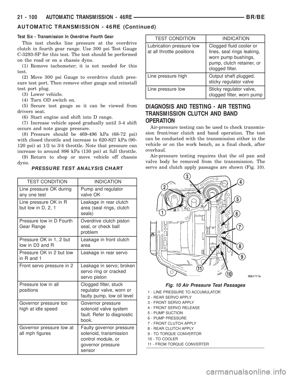
servo and clutch apply passages are shown (Fig. 10).
Fig. 10 Air Pressure Test Passages
1 - LINE PRESSURE TO ACCUMULATOR
2 - REAR SERVO APPLY
3 - FRONT SERVO APPLY
4 - FRONT SERVO RELEASE
5 - PUMP SUCTION
6 - PUMP PRESSURE
7 - FRONT CLUTCH APPLY
8 - REAR CLUTCH APPLY
9 - TO TORQUE CONVERTOR
10 - TO COOLER
11 - FROM TORQUE CONVERTER
21 - 100 AUTOMATIC TRANSMISSION - 46REBR/BE
AUTOMATIC TRANSMISSION - 46RE (Continued)
Page 1559 of 2255
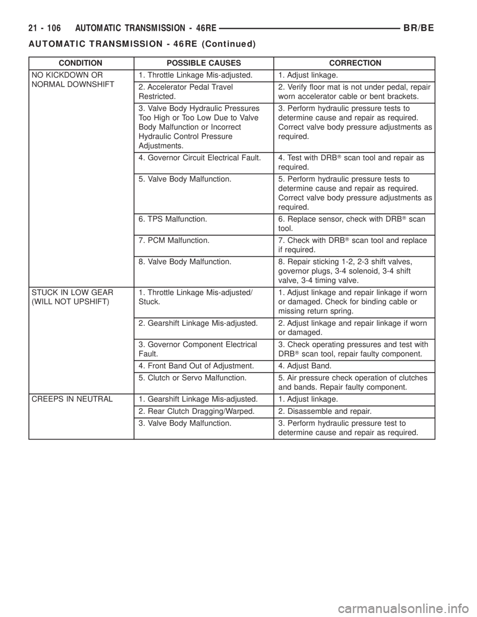
CONDITION POSSIBLE CAUSES CORRECTION
NO KICKDOWN OR
NORMAL DOWNSHIFT1. Throttle Linkage Mis-adjusted. 1. Adjust linkage.
2. Accelerator Pedal Travel
Restricted.2. Verify floor mat is not under pedal, repair
worn accelerator cable or bent brackets.
3. Valve Body Hydraulic Pressures
Too High or Too Low Due to Valve
Body Malfunction or Incorrect
Hydraulic Control Pressure
Adjustments.3. Perform hydraulic pressure tests to
determine cause and repair as required.
Correct valve body pressure adjustments as
required.
4. Governor Circuit Electrical Fault. 4. Test with DRBTscan tool and repair as
required.
5. Valve Body Malfunction. 5. Perform hydraulic pressure tests to
determine cause and repair as required.
Correct valve body pressure adjustments as
required.
6. TPS Malfunction. 6. Replace sensor, check with DRBTscan
tool.
7. PCM Malfunction. 7. Check with DRBTscan tool and replace
if required.
8. Valve Body Malfunction. 8. Repair sticking 1-2, 2-3 shift valves,
governor plugs, 3-4 solenoid, 3-4 shift
valve, 3-4 timing valve.
STUCK IN LOW GEAR
(WILL NOT UPSHIFT)1. Throttle Linkage Mis-adjusted/
Stuck.1. Adjust linkage and repair linkage if worn
or damaged. Check for binding cable or
missing return spring.
2. Gearshift Linkage Mis-adjusted. 2. Adjust linkage and repair linkage if worn
or damaged.
3. Governor Component Electrical
Fault.3. Check operating pressures and test with
DRBTscan tool, repair faulty component.
4. Front Band Out of Adjustment. 4. Adjust Band.
5. Clutch or Servo Malfunction. 5. Air pressure check operation of clutches
and bands. Repair faulty component.
CREEPS IN NEUTRAL 1. Gearshift Linkage Mis-adjusted. 1. Adjust linkage.
2. Rear Clutch Dragging/Warped. 2. Disassemble and repair.
3. Valve Body Malfunction. 3. Perform hydraulic pressure test to
determine cause and repair as required.
21 - 106 AUTOMATIC TRANSMISSION - 46REBR/BE
AUTOMATIC TRANSMISSION - 46RE (Continued)