2002 DODGE RAM sensor
[x] Cancel search: sensorPage 1362 of 2255
SPECIAL TOOLS
DIESEL FUEL SYSTEMFUEL FILTER / WATER
SEPARATOR
DESCRIPTION
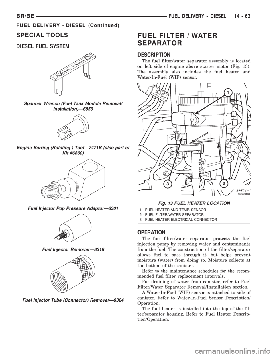
The fuel filter/water separator assembly is located
on left side of engine above starter motor (Fig. 13).
The assembly also includes the fuel heater and
Water-In-Fuel (WIF) sensor.
OPERATION
The fuel filter/water separator protects the fuel
injection pump by removing water and contaminants
from the fuel. The construction of the filter/separator
allows fuel to pass through it, but helps prevent
moisture (water) from doing so. Moisture collects at
the bottom of the canister.
Refer to the maintenance schedules for the recom-
mended fuel filter replacement intervals.
For draining of water from canister, refer to Fuel
Filter/Water Separator Removal/Installation section.
A Water-In-Fuel (WIF) sensor is attached to side of
canister. Refer to Water-In-Fuel Sensor Description/
Operation.
The fuel heater is installed into the top of the fil-
ter/separator housing. Refer to Fuel Heater Descrip-
tion/Operation.
Spanner Wrench (Fuel Tank Module Removal/
Installation)Ð6856
Engine Barring (Rotating ) ToolÐ7471B (also part of
Kit #6860)
Fuel Injector Pop Pressure AdaptorÐ8301
Fuel Injector RemoverÐ8318
Fuel Injector Tube (Connector) RemoverÐ8324
Fig. 13 FUEL HEATER LOCATION
1 - FUEL HEATER AND TEMP. SENSOR
2 - FUEL FILTER/WATER SEPARATOR
3 - FUEL HEATER ELECTRICAL CONNECTOR
BR/BEFUEL DELIVERY - DIESEL 14 - 63
FUEL DELIVERY - DIESEL (Continued)
Page 1363 of 2255
REMOVAL
Refer to maintenance schedules in this manual for
recommended fuel filter replacement intervals.
Draining water from fuel filter/water separa-
tor housing:
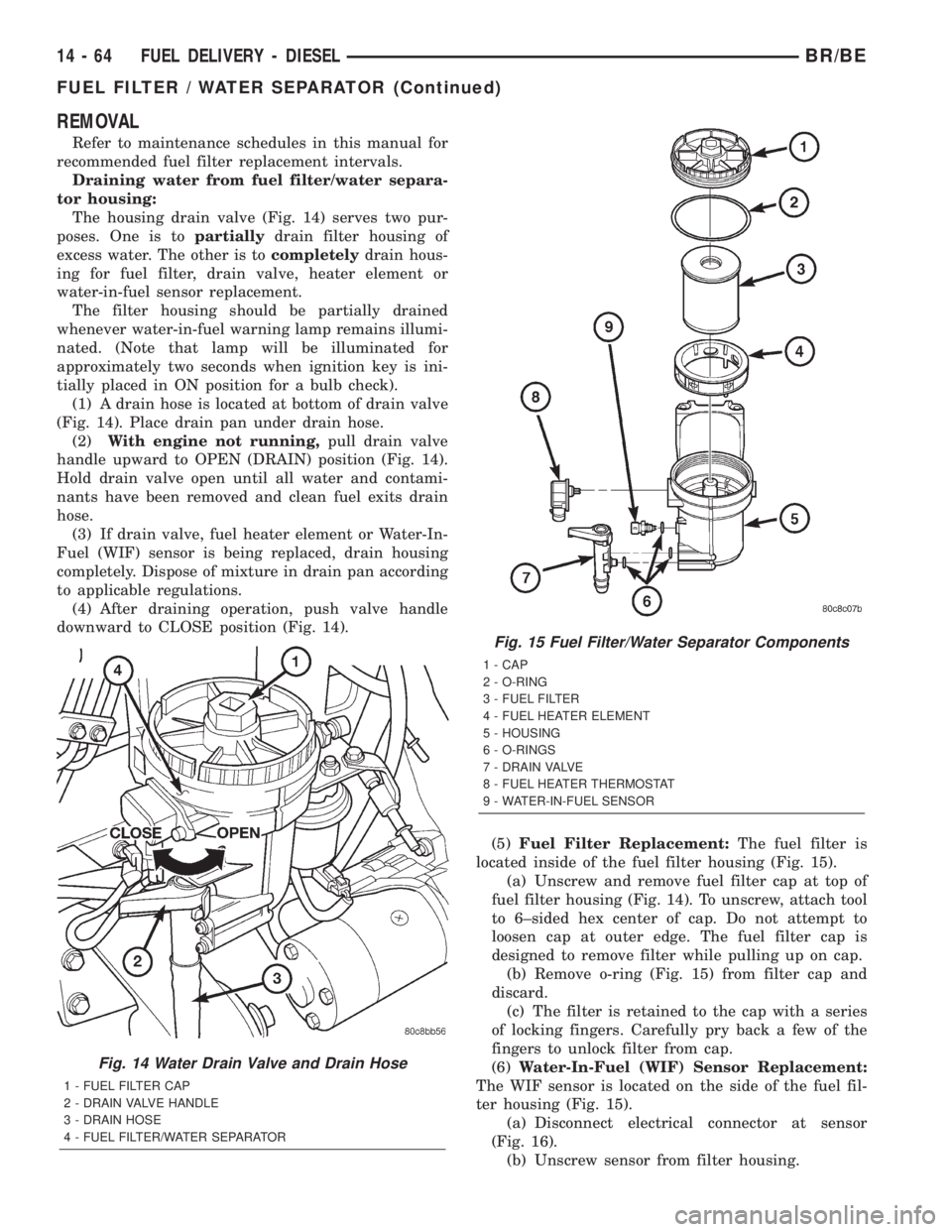
The housing drain valve (Fig. 14) serves two pur-
poses. One is topartiallydrain filter housing of
excess water. The other is tocompletelydrain hous-
ing for fuel filter, drain valve, heater element or
water-in-fuel sensor replacement.
The filter housing should be partially drained
whenever water-in-fuel warning lamp remains illumi-
nated. (Note that lamp will be illuminated for
approximately two seconds when ignition key is ini-
tially placed in ON position for a bulb check).
(1) A drain hose is located at bottom of drain valve
(Fig. 14). Place drain pan under drain hose.
(2)With engine not running,pull drain valve
handle upward to OPEN (DRAIN) position (Fig. 14).
Hold drain valve open until all water and contami-
nants have been removed and clean fuel exits drain
hose.
(3) If drain valve, fuel heater element or Water-In-
Fuel (WIF) sensor is being replaced, drain housing
completely. Dispose of mixture in drain pan according
to applicable regulations.
(4) After draining operation, push valve handle
downward to CLOSE position (Fig. 14).
(5)Fuel Filter Replacement:The fuel filter is
located inside of the fuel filter housing (Fig. 15).
(a) Unscrew and remove fuel filter cap at top of
fuel filter housing (Fig. 14). To unscrew, attach tool
to 6±sided hex center of cap. Do not attempt to
loosen cap at outer edge. The fuel filter cap is
designed to remove filter while pulling up on cap.
(b) Remove o-ring (Fig. 15) from filter cap and
discard.
(c) The filter is retained to the cap with a series
of locking fingers. Carefully pry back a few of the
fingers to unlock filter from cap.
(6)Water-In-Fuel (WIF) Sensor Replacement:
The WIF sensor is located on the side of the fuel fil-
ter housing (Fig. 15).
(a) Disconnect electrical connector at sensor
(Fig. 16).
(b) Unscrew sensor from filter housing.
Fig. 14 Water Drain Valve and Drain Hose
1 - FUEL FILTER CAP
2 - DRAIN VALVE HANDLE
3 - DRAIN HOSE
4 - FUEL FILTER/WATER SEPARATOR
Fig. 15 Fuel Filter/Water Separator Components
1 - CAP
2 - O-RING
3 - FUEL FILTER
4 - FUEL HEATER ELEMENT
5 - HOUSING
6 - O-RINGS
7 - DRAIN VALVE
8 - FUEL HEATER THERMOSTAT
9 - WATER-IN-FUEL SENSOR
14 - 64 FUEL DELIVERY - DIESELBR/BE
FUEL FILTER / WATER SEPARATOR (Continued)
Page 1364 of 2255
(c) Check condition of o-ring.
(d) Inspect the 2 WIF sensor probes. Carefully
clean contaminants from sensor probes with a cloth
if necessary. Replace sensor if probes are covered
with contaminants and will not clean up.
(7)Fuel Heater Element Replacement:The
heater element is located in the fuel filter housing
(Fig. 15).
(a) Remove fuel filter. See previous steps.
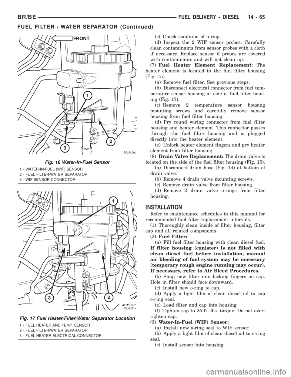
(b) Disconnect electrical connector from fuel tem-
perature sensor housing at side of fuel filter hous-
ing (Fig. 17).
(c) Remove 2 temperature sensor housing
mounting screws and carefully remove sensor
housing from fuel filter housing.
(d) Pry round wiring connector from fuel filter
housing and heater element. This connector passes
through the fuel filter housing and is plugged
directly into the heater element.
(e) Unlock heater element fingers and pry heater
element from filter housing.
(8)Drain Valve Replacement:The drain valve is
located on the side of the fuel filter housing (Fig. 15).
(a) Disconnect drain hose (Fig. 14) at bottom of
drain valve.
(b) Remove 4 drain valve mounting screws.
(c) Remove drain valve from filter housing.
(d) Remove 2 drain valve o-rings from filter
housing.
INSTALLATION
Refer to maintenance schedules in this manual for
recommended fuel filter replacement intervals.
(1) Thoroughly clean inside of filter housing, filter
cap and all related components.
(2)Fuel Filter:
(a) Fill fuel filter housing with clean diesel fuel.
If filter housing (canister) is not filled with
clean diesel fuel before installation, manual
air bleeding of fuel system may be necessary
(temporary rough engine running may occur).
If necessary, refer to Air Bleed Procedures.
(b) Snap new filter into locking fingers on cap.
Hole in filter should face downward.
(c) Install new o-ring to cap.
(d) Apply a light film of clean diesel oil to cap
o-ring seal.
(e) Load filter and cap into housing.
(f) Tighten cap to 25 ft. lbs. torque. Do not over-
tighten cap.
(3)Water-In-Fuel (WIF) Sensor:
(a) Install new o-ring seal to WIF sensor.
(b) Apply a light film of clean diesel oil to o-ring
seal.
(c) Install sensor into housing.
Fig. 16 Water-In-Fuel Sensor
1 - WATER-IN-FUEL (WIF) SENSOR
2 - FUEL FILTER/WATER SEPARATOR
3 - WIF SENSOR CONNECTOR
Fig. 17 Fuel Heater/Filter/Water Separator Location
1 - FUEL HEATER AND TEMP. SENSOR
2 - FUEL FILTER/WATER SEPARATOR
3 - FUEL HEATER ELECTRICAL CONNECTOR
BR/BEFUEL DELIVERY - DIESEL 14 - 65
FUEL FILTER / WATER SEPARATOR (Continued)
Page 1365 of 2255
(d) Tighten sensor to 2±3 N´m (15±20 in. lbs.)
torque.
(e) Connect electrical connector to WIF sensor.
(f) Install fuel filter. Refer to previous steps.
(4)Fuel Heater Element:
(a) Do not install fuel filter until heater element
is installed.
(b) Position heater element into filter housing
(fingers downward). Lock fingers into housing.
(c) Install new o-ring to electrical connector
(where connector passes through filter housing).
Apply a light film of clean diesel oil to o-ring seal.
Press this connector into filter housing until it
snaps into heater element.
(d) Install temperature sensor housing and 2
mounting screws to fuel filter housing.
(e) Connect electrical connector.
(f) Install fuel filter. Refer to previous steps.
(5)Drain Valve:
(a) Install 2 new o-rings to valve and filter hous-
ing.
(b) Apply a light film of clean diesel oil to both
seals.
(c) Position valve to filter housing.
(d) Install 4 mounting screws and tighten to 3±5
N´m (30±40 in. lbs.) torque.
(e) Connect drain hose to drain valve.
(f) Install fuel filter. Refer to previous steps.
(6) Start engine and check for leaks.
FUEL HEATER
DESCRIPTION
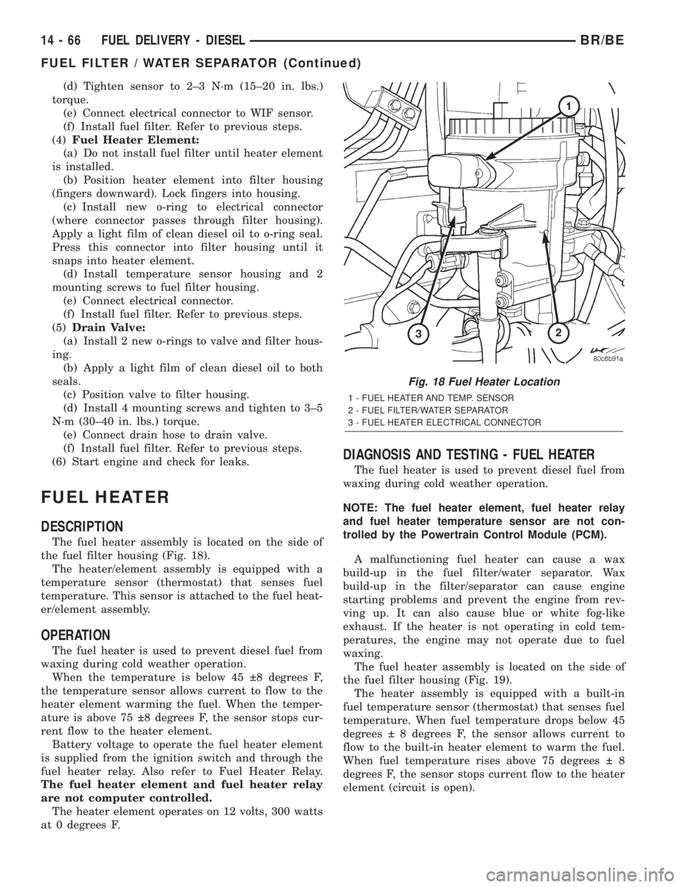
The fuel heater assembly is located on the side of
the fuel filter housing (Fig. 18).
The heater/element assembly is equipped with a
temperature sensor (thermostat) that senses fuel
temperature. This sensor is attached to the fuel heat-
er/element assembly.
OPERATION
The fuel heater is used to prevent diesel fuel from
waxing during cold weather operation.
When the temperature is below 45 8 degrees F,
the temperature sensor allows current to flow to the
heater element warming the fuel. When the temper-
ature is above 75 8 degrees F, the sensor stops cur-
rent flow to the heater element.
Battery voltage to operate the fuel heater element
is supplied from the ignition switch and through the
fuel heater relay. Also refer to Fuel Heater Relay.
The fuel heater element and fuel heater relay
are not computer controlled.
The heater element operates on 12 volts, 300 watts
at 0 degrees F.
DIAGNOSIS AND TESTING - FUEL HEATER
The fuel heater is used to prevent diesel fuel from
waxing during cold weather operation.
NOTE: The fuel heater element, fuel heater relay
and fuel heater temperature sensor are not con-
trolled by the Powertrain Control Module (PCM).
A malfunctioning fuel heater can cause a wax
build-up in the fuel filter/water separator. Wax
build-up in the filter/separator can cause engine
starting problems and prevent the engine from rev-
ving up. It can also cause blue or white fog-like
exhaust. If the heater is not operating in cold tem-
peratures, the engine may not operate due to fuel
waxing.
The fuel heater assembly is located on the side of
the fuel filter housing (Fig. 19).
The heater assembly is equipped with a built-in
fuel temperature sensor (thermostat) that senses fuel
temperature. When fuel temperature drops below 45
degrees 8 degrees F, the sensor allows current to
flow to the built-in heater element to warm the fuel.
When fuel temperature rises above 75 degrees 8
degrees F, the sensor stops current flow to the heater
element (circuit is open).
Fig. 18 Fuel Heater Location
1 - FUEL HEATER AND TEMP. SENSOR
2 - FUEL FILTER/WATER SEPARATOR
3 - FUEL HEATER ELECTRICAL CONNECTOR
14 - 66 FUEL DELIVERY - DIESELBR/BE
FUEL FILTER / WATER SEPARATOR (Continued)
Page 1366 of 2255
Voltage to operate the fuel heater element is sup-
plied from the ignition switch, through the fuel
heater relay (also refer to Fuel Heater Relay), to the
fuel temperature sensor and on to the fuel heater ele-
ment.
The heater element operates on 12 volts, 300 watts
at 0 degrees F. As temperature increases, power
requirements decrease.
A minimum of 7 volts is required to operate the
fuel heater. The resistance value of the heater ele-
ment is less than 1 ohm (cold) and up to 1000 ohms
warm.
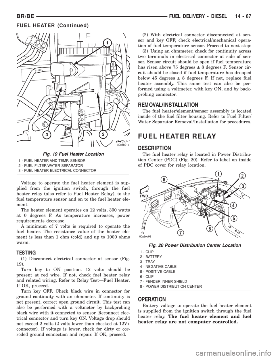
TESTING
(1) Disconnect electrical connector at sensor (Fig.
19).
Turn key to ON position. 12 volts should be
present at red wire. If not, check fuel heater relay
and related wiring. Refer to Relay TestÐFuel Heater.
If OK, proceed.
Turn key OFF. Check black wire in connector for
ground continuity with an ohmmeter. If continuity is
not present, correct open ground circuit. This test can
also be performed with a voltmeter by backprobing
black wire with it connected to sensor. Reconnect elec-
trical connector and turn key ON. Voltage drop should
not exceed 2 volts (2 volts lower than checked at 12V+
connector). If voltage is lower, check for dirty or cor-
roded ground connection and repair. If OK, proceed.
(2) With electrical connector disconnected at sen-
sor and key OFF, check electrical/mechanical opera-
tion of fuel temperature sensor. Proceed to next step:
(3) Using an ohmmeter, check for continuity across
two terminals in electrical connector at side of sen-
sor. Sensor circuit should be open if fuel temperature
has risen above 75 degrees 8 degrees F. Sensor cir-
cuit should be closed if fuel temperature has dropped
below 45 degrees 8 degrees F. If not, replace fuel
heater assembly. This same test can also be per-
formed using a voltmeter, with key ON, and by back-
probing connector.
REMOVAL/INSTALLATION
The fuel heater/element/sensor assembly is located
inside of the fuel filter housing. Refer to Fuel Filter/
Water Separator Removal/Installation for procedures.
FUEL HEATER RELAY
DESCRIPTION
The fuel heater relay is located in Power Distribu-
tion Center (PDC) (Fig. 20). Refer to label on inside
of PDC cover for relay location.
OPERATION
Battery voltage to operate the fuel heater element
is supplied from the ignition switch through the fuel
heater relay.The fuel heater element and fuel
heater relay are not computer controlled.
Fig. 19 Fuel Heater Location
1 - FUEL HEATER AND TEMP. SENSOR
2 - FUEL FILTER/WATER SEPARATOR
3 - FUEL HEATER ELECTRICAL CONNECTOR
Fig. 20 Power Distribution Center Location
1 - CLIP
2 - BATTERY
3 - TRAY
4 - NEGATIVE CABLE
5 - POSITIVE CABLE
6 - CLIP
7 - FENDER INNER SHIELD
8 - POWER DISTRIBUTION CENTER
BR/BEFUEL DELIVERY - DIESEL 14 - 67
FUEL HEATER (Continued)
Page 1369 of 2255
OPERATION
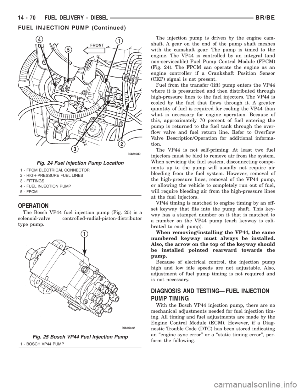
The Bosch VP44 fuel injection pump (Fig. 25) is a
solenoid-valve controlled-radial-piston-distributor
type pump.The injection pump is driven by the engine cam-
shaft. A gear on the end of the pump shaft meshes
with the camshaft gear. The pump is timed to the
engine. The VP44 is controlled by an integral (and
non-serviceable) Fuel Pump Control Module (FPCM)
(Fig. 24). The FPCM can operate the engine as an
engine controller if a Crankshaft Position Sensor
(CKP) signal is not present.
Fuel from the transfer (lift) pump enters the VP44
where it is pressurized and then distributed through
high-pressure lines to the fuel injectors. The VP44 is
cooled by the fuel that flows through it. A greater
quantity of fuel is required for cooling the VP44 than
what is necessary for engine operation. Because of
this, approximately 70 percent of fuel entering the
pump is returned to the fuel tank through the over-
flow valve and fuel return line. Refer to Overflow
Valve Description/Operation for additional informa-
tion.
The VP44 is not self-priming. At least two fuel
injectors must be bled to remove air from the system.
When servicing the fuel system, disconnecting compo-
nents up to the pump will usually not require air
bleeding from the fuel system. However, removal of
the high-pressure lines, removal of the VP44 pump,
or allowing the vehicle to completely run out of fuel,
will require bleeding air from the high-pressure lines
at the fuel injectors.
VP44 timing is matched to engine timing by an off-
set keyway that fits into the pump shaft. This key-
way has a stamped number on it that is matched to
a number on the VP44 pump (each keyway is cali-
brated to each pump).
When removing/installing the VP44, the same
numbered keyway must always be installed.
Also, the arrow on the top of the keyway should
be installed pointed rearward towards the
pump.
Because of electrical control, the injection pump
high and low idle speeds are not adjustable. Also,
adjustment of fuel pump timing is not required and
is not necessary.
DIAGNOSIS AND TESTINGÐFUEL INJECTION
PUMP TIMING
With the Bosch VP44 injection pump, there are no
mechanical adjustments needed for fuel injection tim-
ing. All timing and fuel adjustments are made by the
Engine Control Module (ECM). However, if a Diag-
nostic Trouble Code (DTC) has been stored indicating
an ªengine sync errorº or a ªstatic timing errorº, per-
form the following.
Fig. 24 Fuel Injection Pump Location
1 - FPCM ELECTRICAL CONNECTOR
2 - HIGH-PRESSURE FUEL LINES
3 - FITTINGS
4 - FUEL INJECTION PUMP
5 - FPCM
Fig. 25 Bosch VP44 Fuel Injection Pump
1 - BOSCH VP44 PUMP
14 - 70 FUEL DELIVERY - DIESELBR/BE
FUEL INJECTION PUMP (Continued)
Page 1371 of 2255
(1) Remove hose clamp and crankcase vent hose at
crankcase breather (Fig. 26). Remove crankcase
breather from gear cover. Breather threads into
cover.
(2) Remove injection pump nut and washer (Fig.
27). Locate keyway behind washer.
(3) Be sure keyway aligning fuel injection pump
shaft to injection pump gear is in proper position and
pump gear has not slipped on pump shaft.
The following steps will require removing timing
gear cover to gain access to timing gears. Refer to
Group 9, Engines for procedures.
(4) Use a T-type puller to separate injection pump
gear from pump shaft.
(5) Be sure keyway has been installed with arrow
pointed torearof pump (Fig. 28).
(6)Pump timing has been calibrated to pump
keyway. Be sure 3±digit number on pump key-
way (Fig. 28) matches 3±digit number on fuel
injection pump data plate. Plate is located on
side of injection pump (Fig. 29). Twenty±one dif-
ferent calibrated keyways/pumps are available.
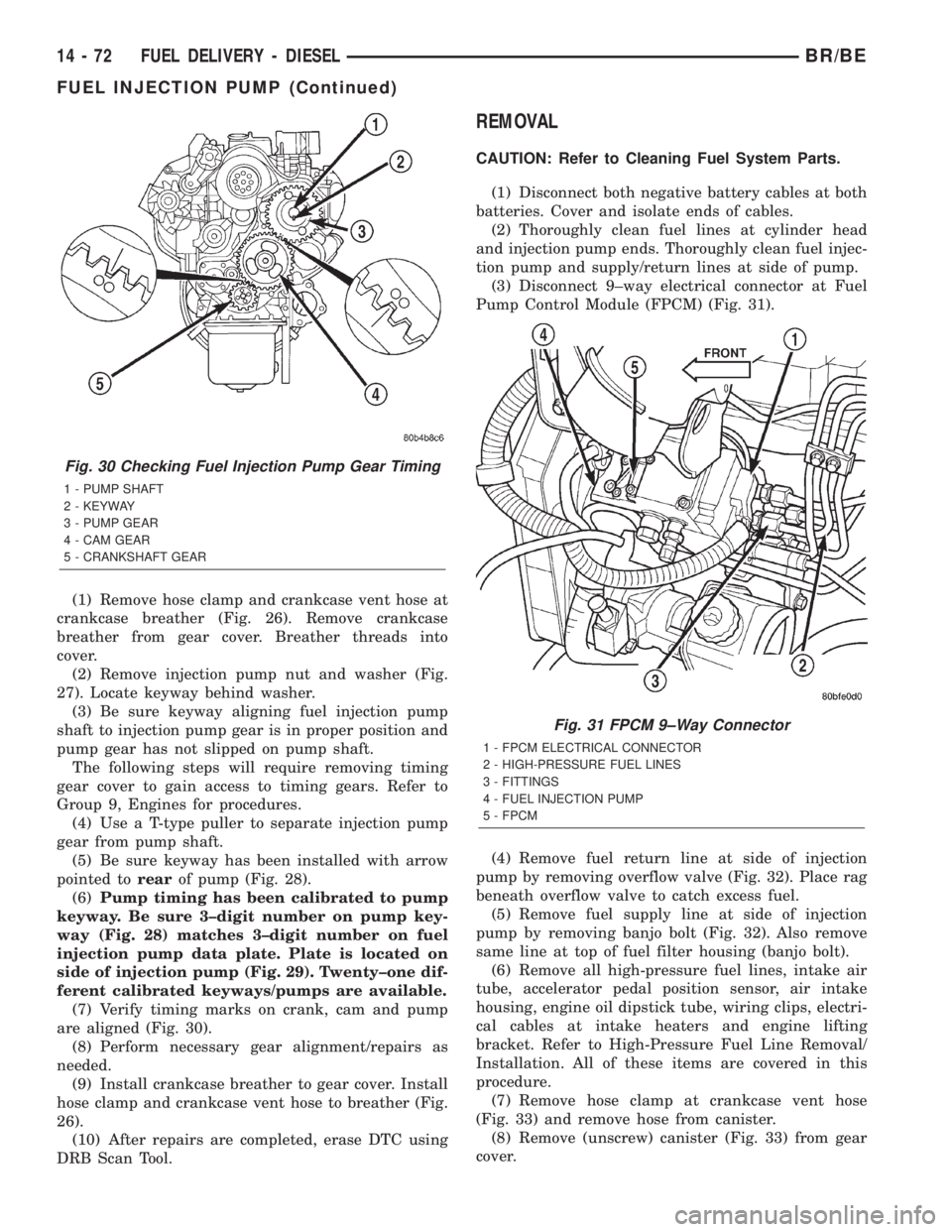
(7) Verify timing marks on crank, cam and pump
are aligned (Fig. 30).
(8) Perform necessary gear alignment/repairs as
needed.
(9) Install crankcase breather to gear cover. Install
hose clamp and crankcase vent hose to breather (Fig.
26).
(10) After repairs are completed, erase DTC using
DRB Scan Tool.
REMOVAL
CAUTION: Refer to Cleaning Fuel System Parts.
(1) Disconnect both negative battery cables at both
batteries. Cover and isolate ends of cables.
(2) Thoroughly clean fuel lines at cylinder head
and injection pump ends. Thoroughly clean fuel injec-
tion pump and supply/return lines at side of pump.
(3) Disconnect 9±way electrical connector at Fuel
Pump Control Module (FPCM) (Fig. 31).
(4) Remove fuel return line at side of injection
pump by removing overflow valve (Fig. 32). Place rag
beneath overflow valve to catch excess fuel.
(5) Remove fuel supply line at side of injection
pump by removing banjo bolt (Fig. 32). Also remove
same line at top of fuel filter housing (banjo bolt).
(6) Remove all high-pressure fuel lines, intake air
tube, accelerator pedal position sensor, air intake
housing, engine oil dipstick tube, wiring clips, electri-
cal cables at intake heaters and engine lifting
bracket. Refer to High-Pressure Fuel Line Removal/
Installation. All of these items are covered in this
procedure.
(7) Remove hose clamp at crankcase vent hose
(Fig. 33) and remove hose from canister.
(8) Remove (unscrew) canister (Fig. 33) from gear
cover.
Fig. 30 Checking Fuel Injection Pump Gear Timing
1 - PUMP SHAFT
2 - KEYWAY
3 - PUMP GEAR
4 - CAM GEAR
5 - CRANKSHAFT GEAR
Fig. 31 FPCM 9±Way Connector
1 - FPCM ELECTRICAL CONNECTOR
2 - HIGH-PRESSURE FUEL LINES
3 - FITTINGS
4 - FUEL INJECTION PUMP
5 - FPCM
14 - 72 FUEL DELIVERY - DIESELBR/BE
FUEL INJECTION PUMP (Continued)
Page 1375 of 2255
The machined tapers on both injection pump
shaft and injection pump gear (Fig. 42) must be
absolutely dry, clean and free of any dirt or oil
film. This will ensure proper gear-to-shaft tight-
ening.
(5) Clean pump gear and pump shaft at machined
tapers (Fig. 42) with an evaporative type cleaner
such as brake cleaner.
Keyway Installation:
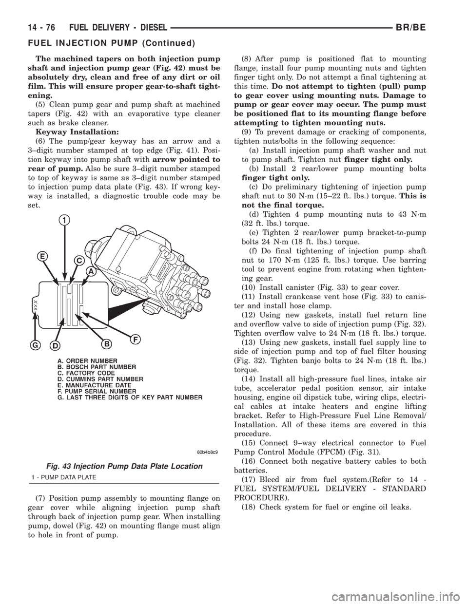
(6) The pump/gear keyway has an arrow and a
3±digit number stamped at top edge (Fig. 41). Posi-
tion keyway into pump shaft witharrow pointed to
rear of pump.Also be sure 3±digit number stamped
to top of keyway is same as 3±digit number stamped
to injection pump data plate (Fig. 43). If wrong key-
way is installed, a diagnostic trouble code may be
set.
(7) Position pump assembly to mounting flange on
gear cover while aligning injection pump shaft
through back of injection pump gear. When installing
pump, dowel (Fig. 42) on mounting flange must align
to hole in front of pump.(8) After pump is positioned flat to mounting
flange, install four pump mounting nuts and tighten
finger tight only. Do not attempt a final tightening at
this time.Do not attempt to tighten (pull) pump
to gear cover using mounting nuts. Damage to
pump or gear cover may occur. The pump must
be positioned flat to its mounting flange before
attempting to tighten mounting nuts.
(9) To prevent damage or cracking of components,
tighten nuts/bolts in the following sequence:
(a) Install injection pump shaft washer and nut
to pump shaft. Tighten nutfinger tight only.
(b) Install 2 rear/lower pump mounting bolts
finger tight only.
(c) Do preliminary tightening of injection pump
shaft nut to 30 N´m (15±22 ft. lbs.) torque.This is
not the final torque.
(d) Tighten 4 pump mounting nuts to 43 N´m
(32 ft. lbs.) torque.
(e) Tighten 2 rear/lower pump bracket-to-pump
bolts 24 N´m (18 ft. lbs.) torque.
(f) Do final tightening of injection pump shaft
nut to 170 N´m (125 ft. lbs.) torque. Use barring
tool to prevent engine from rotating when tighten-
ing gear.
(10) Install canister (Fig. 33) to gear cover.
(11) Install crankcase vent hose (Fig. 33) to canis-
ter and install hose clamp.
(12) Using new gaskets, install fuel return line
and overflow valve to side of injection pump (Fig. 32).
Tighten overflow valve to 24 N´m (18 ft. lbs.) torque.
(13) Using new gaskets, install fuel supply line to
side of injection pump and top of fuel filter housing
(Fig. 32). Tighten banjo bolts to 24 N´m (18 ft. lbs.)
torque.
(14) Install all high-pressure fuel lines, intake air
tube, accelerator pedal position sensor, air intake
housing, engine oil dipstick tube, wiring clips, electri-
cal cables at intake heaters and engine lifting
bracket. Refer to High-Pressure Fuel Line Removal/
Installation. All of these items are covered in this
procedure.
(15) Connect 9±way electrical connector to Fuel
Pump Control Module (FPCM) (Fig. 31).
(16) Connect both negative battery cables to both
batteries.
(17) Bleed air from fuel system.(Refer to 14 -
FUEL SYSTEM/FUEL DELIVERY - STANDARD
PROCEDURE).
(18) Check system for fuel or engine oil leaks.
Fig. 43 Injection Pump Data Plate Location
1 - PUMP DATA PLATE
14 - 76 FUEL DELIVERY - DIESELBR/BE
FUEL INJECTION PUMP (Continued)