2002 DODGE RAM sensor
[x] Cancel search: sensorPage 1347 of 2255
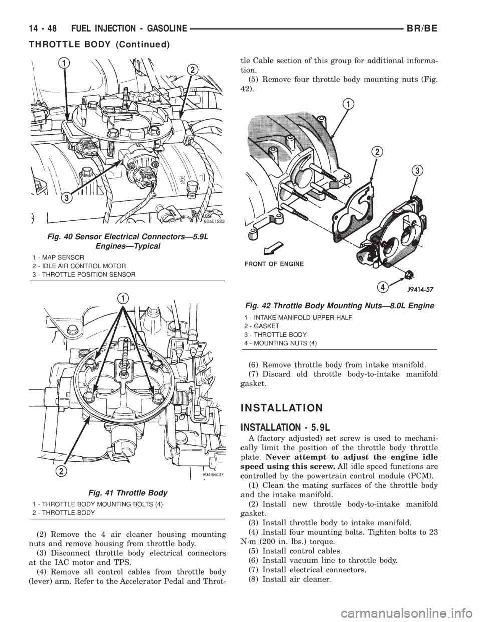
(2) Remove the 4 air cleaner housing mounting
nuts and remove housing from throttle body.
(3) Disconnect throttle body electrical connectors
at the IAC motor and TPS.
(4) Remove all control cables from throttle body
(lever) arm. Refer to the Accelerator Pedal and Throt-tle Cable section of this group for additional informa-
tion.
(5) Remove four throttle body mounting nuts (Fig.
42).
(6) Remove throttle body from intake manifold.
(7) Discard old throttle body-to-intake manifold
gasket.
INSTALLATION
INSTALLATION - 5.9L
A (factory adjusted) set screw is used to mechani-
cally limit the position of the throttle body throttle
plate.Never attempt to adjust the engine idle
speed using this screw.All idle speed functions are
controlled by the powertrain control module (PCM).
(1) Clean the mating surfaces of the throttle body
and the intake manifold.
(2) Install new throttle body-to-intake manifold
gasket.
(3) Install throttle body to intake manifold.
(4) Install four mounting bolts. Tighten bolts to 23
N´m (200 in. lbs.) torque.
(5) Install control cables.
(6) Install vacuum line to throttle body.
(7) Install electrical connectors.
(8) Install air cleaner.
Fig. 40 Sensor Electrical ConnectorsÐ5.9L
EnginesÐTypical
1 - MAP SENSOR
2 - IDLE AIR CONTROL MOTOR
3 - THROTTLE POSITION SENSOR
Fig. 41 Throttle Body
1 - THROTTLE BODY MOUNTING BOLTS (4)
2 - THROTTLE BODY
Fig. 42 Throttle Body Mounting NutsÐ8.0L Engine
1 - INTAKE MANIFOLD UPPER HALF
2 - GASKET
3 - THROTTLE BODY
4 - MOUNTING NUTS (4)
14 - 48 FUEL INJECTION - GASOLINEBR/BE
THROTTLE BODY (Continued)
Page 1349 of 2255
INSTALLATION
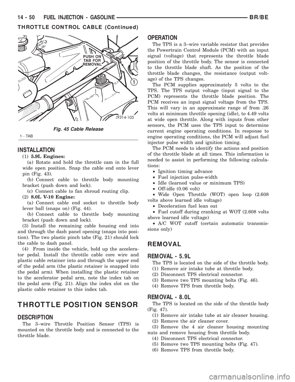
(1)5.9L Engines:
(a) Rotate and hold the throttle cam in the full
wide open position. Snap the cable end onto lever
pin (Fig. 43).
(b) Connect cable to throttle body mounting
bracket (push down and lock).
(c) Connect cable to fan shroud routing clip.
(2)8.0L V-10 Engine:
(a) Connect cable end socket to throttle body
lever ball (snaps on) (Fig. 44).
(b) Connect cable to throttle body mounting
bracket (push down and lock).
(3) Install the remaining cable housing end into
and through the dash panel opening (snaps into posi-
tion). The two plastic pinch tabs (Fig. 21) should lock
the cable to dash panel.
(4) From inside the vehicle, hold up the accelera-
tor pedal. Install the throttle cable core wire and
plastic cable retainer into and through the upper end
of the pedal arm (the plastic retainer is snapped into
the pedal arm). When installing the plastic retainer
to the accelerator pedal arm, note the index tab on
the pedal arm (Fig. 21). Align the index slot on the
plastic cable retainer to this index tab.
THROTTLE POSITION SENSOR
DESCRIPTION
The 3±wire Throttle Position Sensor (TPS) is
mounted on the throttle body and is connected to the
throttle blade.
OPERATION
The TPS is a 3±wire variable resistor that provides
the Powertrain Control Module (PCM) with an input
signal (voltage) that represents the throttle blade
position of the throttle body. The sensor is connected
to the throttle blade shaft. As the position of the
throttle blade changes, the resistance (output volt-
age) of the TPS changes.
The PCM supplies approximately 5 volts to the
TPS. The TPS output voltage (input signal to the
PCM) represents the throttle blade position. The
PCM receives an input signal voltage from the TPS.
This will vary in an approximate range of from .26
volts at minimum throttle opening (idle), to 4.49 volts
at wide open throttle. Along with inputs from other
sensors, the PCM uses the TPS input to determine
current engine operating conditions. In response to
engine operating conditions, the PCM will adjust fuel
injector pulse width and ignition timing.
The PCM needs to identify the actions and position
of the throttle blade at all times. This information is
needed to assist in performing the following calcula-
tions:
²Ignition timing advance
²Fuel injection pulse-width
²Idle (learned value or minimum TPS)
²Off-idle (0.06 volt)
²Wide Open Throttle (WOT) open loop (2.608
volts above learned idle voltage)
²Deceleration fuel lean out
²Fuel cutoff during cranking at WOT (2.608 volts
above learned idle voltage)
²A/C WOT cutoff (certain automatic transmis-
sions only)
REMOVAL
REMOVAL - 5.9L
The TPS is located on the side of the throttle body.
(1) Remove air intake tube at throttle body.
(2) Disconnect TPS electrical connector.
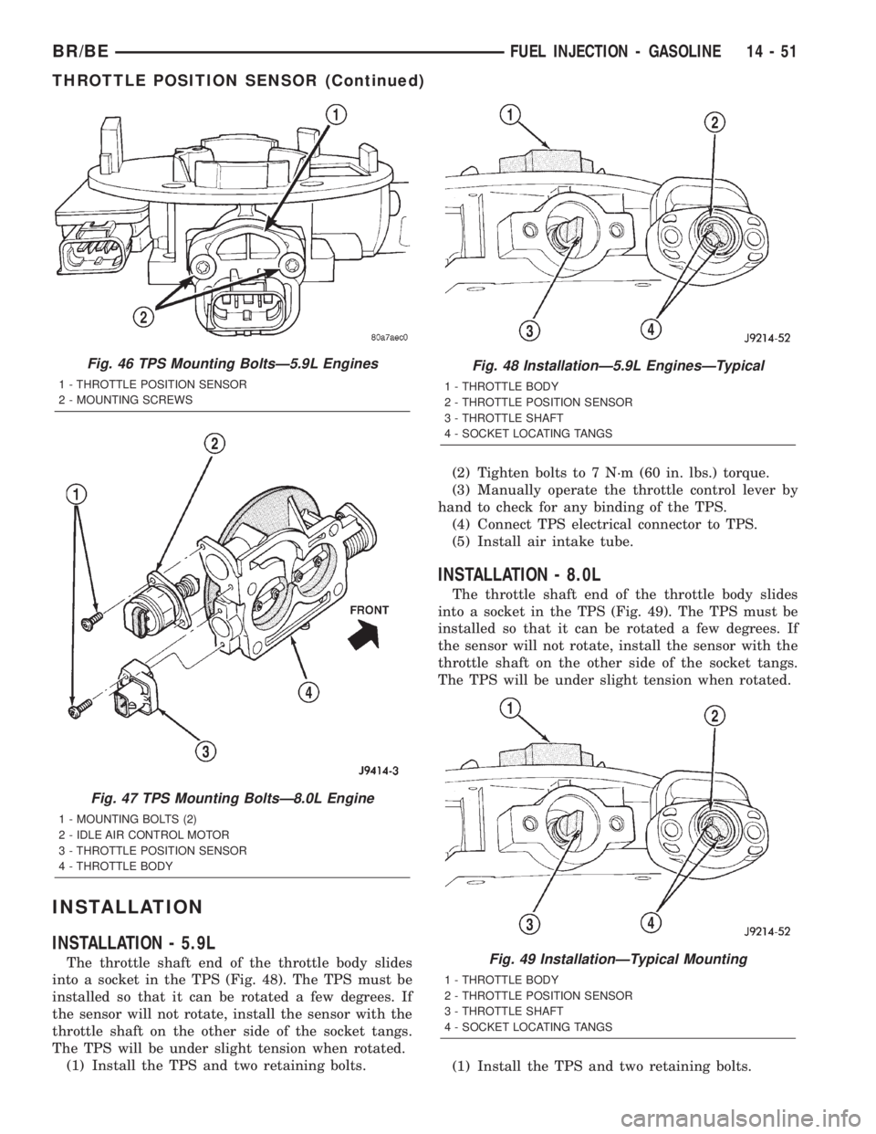
(3) Remove two TPS mounting bolts (Fig. 46).
(4) Remove TPS from throttle body.
REMOVAL - 8.0L
The TPS is located on the side of the throttle body
(Fig. 47).
(1) Remove air intake tube at air cleaner housing.
(2) Remove the air cleaner cover.
(3) Remove the 4 air cleaner housing mounting
nuts and remove housing from throttle body.
(4) Disconnect TPS electrical connector.
(5) Remove two TPS mounting bolts (Fig. 47).
(6) Remove TPS from throttle body.
Fig. 45 Cable Release
1-TAB
14 - 50 FUEL INJECTION - GASOLINEBR/BE
THROTTLE CONTROL CABLE (Continued)
Page 1350 of 2255
INSTALLATION
INSTALLATION - 5.9L
The throttle shaft end of the throttle body slides
into a socket in the TPS (Fig. 48). The TPS must be
installed so that it can be rotated a few degrees. If
the sensor will not rotate, install the sensor with the
throttle shaft on the other side of the socket tangs.
The TPS will be under slight tension when rotated.
(1) Install the TPS and two retaining bolts.(2) Tighten bolts to 7 N´m (60 in. lbs.) torque.
(3) Manually operate the throttle control lever by
hand to check for any binding of the TPS.
(4) Connect TPS electrical connector to TPS.
(5) Install air intake tube.
INSTALLATION - 8.0L
The throttle shaft end of the throttle body slides
into a socket in the TPS (Fig. 49). The TPS must be
installed so that it can be rotated a few degrees. If
the sensor will not rotate, install the sensor with the
throttle shaft on the other side of the socket tangs.
The TPS will be under slight tension when rotated.
(1) Install the TPS and two retaining bolts.
Fig. 46 TPS Mounting BoltsÐ5.9L Engines
1 - THROTTLE POSITION SENSOR
2 - MOUNTING SCREWS
Fig. 47 TPS Mounting BoltsÐ8.0L Engine
1 - MOUNTING BOLTS (2)
2 - IDLE AIR CONTROL MOTOR
3 - THROTTLE POSITION SENSOR
4 - THROTTLE BODY
Fig. 48 InstallationÐ5.9L EnginesÐTypical
1 - THROTTLE BODY
2 - THROTTLE POSITION SENSOR
3 - THROTTLE SHAFT
4 - SOCKET LOCATING TANGS
Fig. 49 InstallationÐTypical Mounting
1 - THROTTLE BODY
2 - THROTTLE POSITION SENSOR
3 - THROTTLE SHAFT
4 - SOCKET LOCATING TANGS
BR/BEFUEL INJECTION - GASOLINE 14 - 51
THROTTLE POSITION SENSOR (Continued)
Page 1351 of 2255
(2) Tighten bolts to 7 N´m (60 in. lbs.) torque.
(3) Manually operate the throttle control lever by
hand to check for any binding of the TPS.
(4) Connect TPS electrical connector to TPS.
(5) Install air cleaner housing to throttle body.
(6) Install 4 air cleaner housing mounting nuts.
Tighten nuts to 11 N´m (96 in. lbs.) torque.
(7) Install air cleaner housing cover.
(8) Install air intake tube to cover.
FUEL INJECTOR
DESCRIPTION
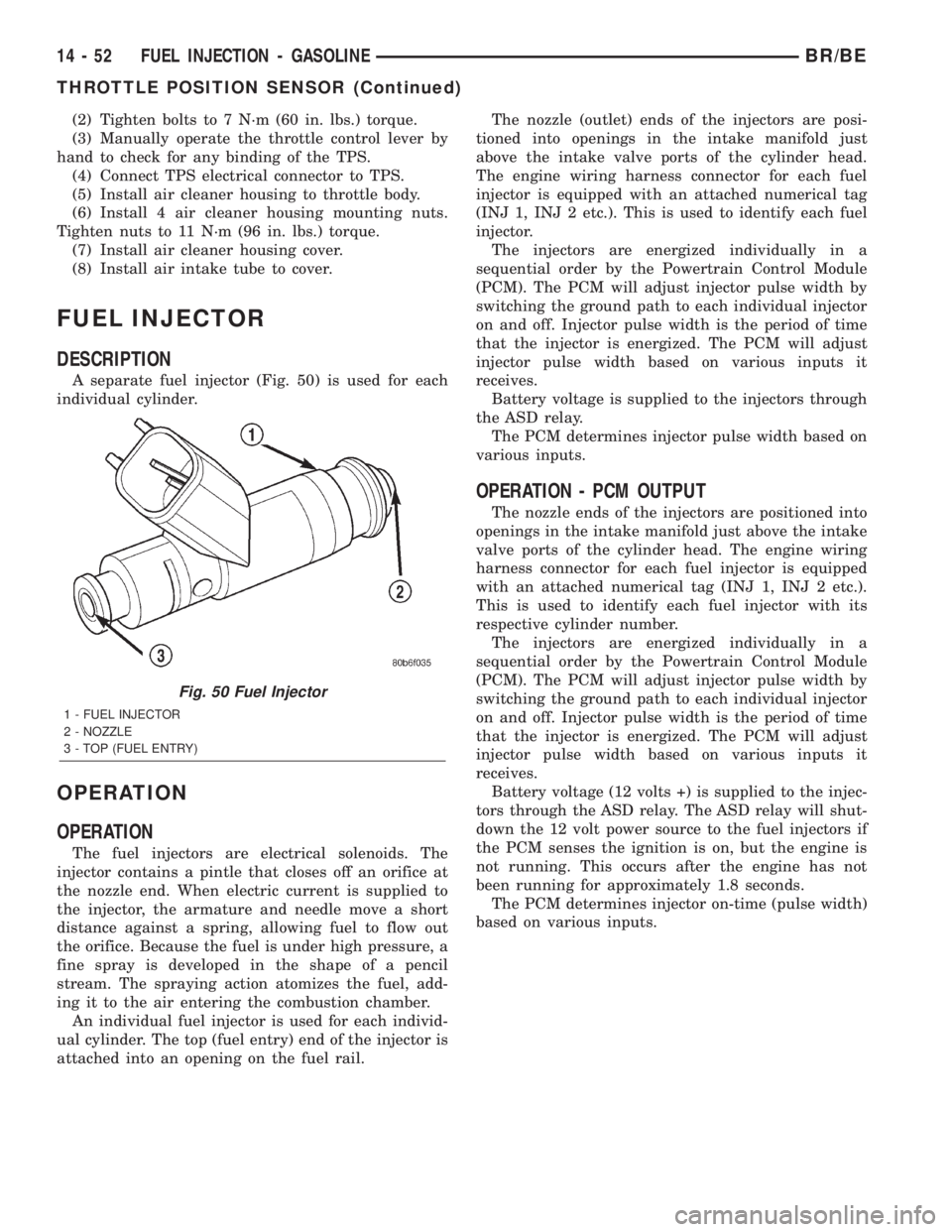
A separate fuel injector (Fig. 50) is used for each
individual cylinder.
OPERATION
OPERATION
The fuel injectors are electrical solenoids. The
injector contains a pintle that closes off an orifice at
the nozzle end. When electric current is supplied to
the injector, the armature and needle move a short
distance against a spring, allowing fuel to flow out
the orifice. Because the fuel is under high pressure, a
fine spray is developed in the shape of a pencil
stream. The spraying action atomizes the fuel, add-
ing it to the air entering the combustion chamber.
An individual fuel injector is used for each individ-
ual cylinder. The top (fuel entry) end of the injector is
attached into an opening on the fuel rail.The nozzle (outlet) ends of the injectors are posi-
tioned into openings in the intake manifold just
above the intake valve ports of the cylinder head.
The engine wiring harness connector for each fuel
injector is equipped with an attached numerical tag
(INJ 1, INJ 2 etc.). This is used to identify each fuel
injector.
The injectors are energized individually in a
sequential order by the Powertrain Control Module
(PCM). The PCM will adjust injector pulse width by
switching the ground path to each individual injector
on and off. Injector pulse width is the period of time
that the injector is energized. The PCM will adjust
injector pulse width based on various inputs it
receives.
Battery voltage is supplied to the injectors through
the ASD relay.
The PCM determines injector pulse width based on
various inputs.
OPERATION - PCM OUTPUT
The nozzle ends of the injectors are positioned into
openings in the intake manifold just above the intake
valve ports of the cylinder head. The engine wiring
harness connector for each fuel injector is equipped
with an attached numerical tag (INJ 1, INJ 2 etc.).
This is used to identify each fuel injector with its
respective cylinder number.
The injectors are energized individually in a
sequential order by the Powertrain Control Module
(PCM). The PCM will adjust injector pulse width by
switching the ground path to each individual injector
on and off. Injector pulse width is the period of time
that the injector is energized. The PCM will adjust
injector pulse width based on various inputs it
receives.
Battery voltage (12 volts +) is supplied to the injec-
tors through the ASD relay. The ASD relay will shut-
down the 12 volt power source to the fuel injectors if
the PCM senses the ignition is on, but the engine is
not running. This occurs after the engine has not
been running for approximately 1.8 seconds.
The PCM determines injector on-time (pulse width)
based on various inputs.
Fig. 50 Fuel Injector
1 - FUEL INJECTOR
2 - NOZZLE
3 - TOP (FUEL ENTRY)
14 - 52 FUEL INJECTION - GASOLINEBR/BE
THROTTLE POSITION SENSOR (Continued)
Page 1353 of 2255
FUEL DELIVERY - DIESEL
TABLE OF CONTENTS
page page
FUEL DELIVERY - DIESEL
DESCRIPTION
DESCRIPTION - DIESEL FUEL DELIVERY
SYSTEM............................55
OPERATION.........................55
DIAGNOSIS AND TESTING
DIAGNOSIS AND TESTING - FUEL SYSTEM
AIR LEAK VACUUM TEST...............57
DIAGNOSIS AND TESTING - AIR IN FUEL
SYSTEM............................60
DIAGNOSIS AND TESTING - FUEL SUPPLY
RESTRICTIONS.......................60
STANDARD PROCEDURE
STANDARD PROCEDURES - WATER
DRAINING AT FUEL FILTER..............61
STANDARD PROCEDURES - CLEANING
FUEL SYSTEM PARTS.................61
STANDARD PROCEDURE - AIR BLEED....61
SPECIFICATIONS
FUEL SYSTEM PRESSURESÐDIESEL
ENGINES............................62
FUEL INJECTOR FIRING ORDERÐDIESEL . 62
SPECIAL TOOLS
DIESEL FUEL SYSTEM.................63
FUEL FILTER / WATER SEPARATOR
DESCRIPTION.........................63
OPERATION...........................63
REMOVAL.............................64
INSTALLATION.........................65
FUEL HEATER
DESCRIPTION.........................66
OPERATION...........................66
DIAGNOSIS AND TESTING - FUEL HEATER . . . 66
REMOVAL/INSTALLATION................67
FUEL HEATER RELAY
DESCRIPTION.........................67
OPERATION...........................67
DIAGNOSIS AND TESTING - FUEL HEATER
RELAY..............................68
REMOVAL.............................69
INSTALLATION.........................69
FUEL INJECTION PUMP
DESCRIPTION
DESCRIPTIONÐFUEL PUMP 245 H.P......69
DESCRIPTIONÐFUEL PUMP 235 H.P......69
OPERATION...........................70
DIAGNOSIS AND TESTINGÐFUEL INJECTION
PUMP TIMING........................70REMOVAL.............................72
INSTALLATION.........................75
FUEL INJECTION PUMP DATA PLATE
SPECIFICATIONS
FUEL INJECTION PUMP DATA PLATE......77
FUEL LEVEL SENDING UNIT / SENSOR
DESCRIPTION.........................77
OPERATION...........................77
FUEL LINES
DESCRIPTION
DESCRIPTION........................77
DESCRIPTIONÐHIGH PRESSURE FUEL
LINES..............................78
OPERATIONÐHIGH PRESSURE FUEL LINES . 78
DIAGNOSIS AND TESTING - HIGH-
PRESSURE FUEL LINE LEAKS...........78
REMOVAL.............................79
INSTALLATION.........................81
FUEL TANK
DESCRIPTION - DIESEL FUEL TANK........82
FUEL TANK MODULE
DESCRIPTION.........................82
OPERATION...........................82
REMOVAL.............................83
INSTALLATION.........................83
FUEL TRANSFER PUMP
DESCRIPTION.........................83
OPERATION...........................83
DIAGNOSIS AND TESTING - FUEL TRANSFER
PUMP PRESSURE.....................84
REMOVAL.............................86
INSTALLATION.........................87
OVERFLOW VALVE
DESCRIPTION.........................87
OPERATION...........................87
DIAGNOSIS AND TESTING - OVERFLOW
VALVE ..............................87
REMOVAL.............................88
INSTALLATION.........................88
WATER IN FUEL SENSOR
DESCRIPTION.........................89
OPERATION...........................89
REMOVAL.............................89
FUEL DRAIN MANIFOLD
DESCRIPTION.........................89
OPERATION...........................89
REMOVAL.............................90
INSTALLATION.........................90
14 - 54 FUEL DELIVERY - DIESELBR/BE
Page 1354 of 2255
FUEL DELIVERY - DIESEL
DESCRIPTION
DESCRIPTION - DIESEL FUEL DELIVERY
SYSTEM
The fuel system on the Cummins 24 valveÐTurbo
Diesel Engine uses anelectronically controlled
fuel injection pump with three control modules.
Also refer to the Powertrain Control Module (PCM)
or Engine Control Module sections.
Some fuel system components are shown in (Fig.
1).
The fuel delivery system consists of the:
²Accelerator pedal
²Air cleaner housing/element
²Fuel drain manifold (passage)
²Fuel filter/water separator
²Fuel heater
²Fuel heater relay
²Fuel transfer (lift) pump
²Fuel injection pump
²Fuel injectors
²Fuel heater temperature sensor
²Fuel tank
²Fuel tank filler/vent tube assembly²Fuel tank filler tube cap
²Fuel tank module containing the rollover valve,
fuel gauge sending unit (fuel level sensor) and a sep-
arate fuel filter located at bottom of tank module
²Fuel tubes/lines/hoses
²High-pressure fuel injector lines
²In-tank fuel filter (at bottom of fuel tank mod-
ule)
²Low-pressure fuel supply lines
²Low-pressure fuel return line
²Overflow valve
²Quick-connect fittings
²Throttle cable
²Water draining
OPERATION
WARNING: HIGH-PRESSURE FUEL LINES DELIVER
DIESEL FUEL UNDER EXTREME PRESSURE FROM
THE INJECTION PUMP TO THE FUEL INJECTORS.
THIS MAY BE AS HIGH AS 120,000 KPA (17,405
PSI). USE EXTREME CAUTION WHEN INSPECTING
FOR HIGH-PRESSURE FUEL LEAKS. INSPECT FOR
HIGH-PRESSURE FUEL LEAKS WITH A SHEET OF
CARDBOARD. HIGH FUEL INJECTION PRESSURE
CAN CAUSE PERSONAL INJURY IF CONTACT IS
MADE WITH THE SKIN.
BR/BEFUEL DELIVERY - DIESEL 14 - 55
Page 1355 of 2255

Fig. 1 FUEL SYSTEM COMPONENTS - DIESEL
1 - ENGINE COOLANT TEMPERATURE (ECT) SENSOR 14 - FUEL SUPPLY LINE (LOW-PRESSURE, TO ENGINE)
2 - THROTTLE LEVER BELLCRANK AND APPS (ACCELERATOR
PEDAL POSITION SENSOR)15 - FUEL TRANSFER (LIFT) PUMP
3 - INTAKE MANIFOLD AIR HEATER/ELEMENTS 16 - OIL PRESSURE SENSOR
4 - HIGH-PRESSURE FUEL LINES 17 - FUEL FILTER/WATER SEPARATOR
5 - FUEL HEATER 18 - DRAIN TUBE
6 - FUEL PRESSURE TEST PORT 19 - WATER-IN-FUEL (WIF) SENSOR
7 - MAP (BOOST) SENSOR 20 - ENGINE CONTROL MODULE (ECM)
8 - FUEL INJECTORS 21 - FUEL PRESSURE TEST PORT
9 - FUEL INJECTOR CONNECTOR 22 - CAMSHAFT POSITION SENSOR (CMP)
10 - INTAKE AIR TEMPERATURE (IAT) SENSOR 23 - OVERFLOW VALVE
11 - FUEL DRAIN MANIFOLD 24 - FUEL INJECTION PUMP
12 - DRAIN VALVE 25 - FUEL HEATER TEMPERATURE SENSOR (THERMOSTAT)
13 - FUEL RETURN LINE (TO FUEL TANK)
14 - 56 FUEL DELIVERY - DIESELBR/BE
FUEL DELIVERY - DIESEL (Continued)
Page 1357 of 2255
Testing Fuel Transfer Pump
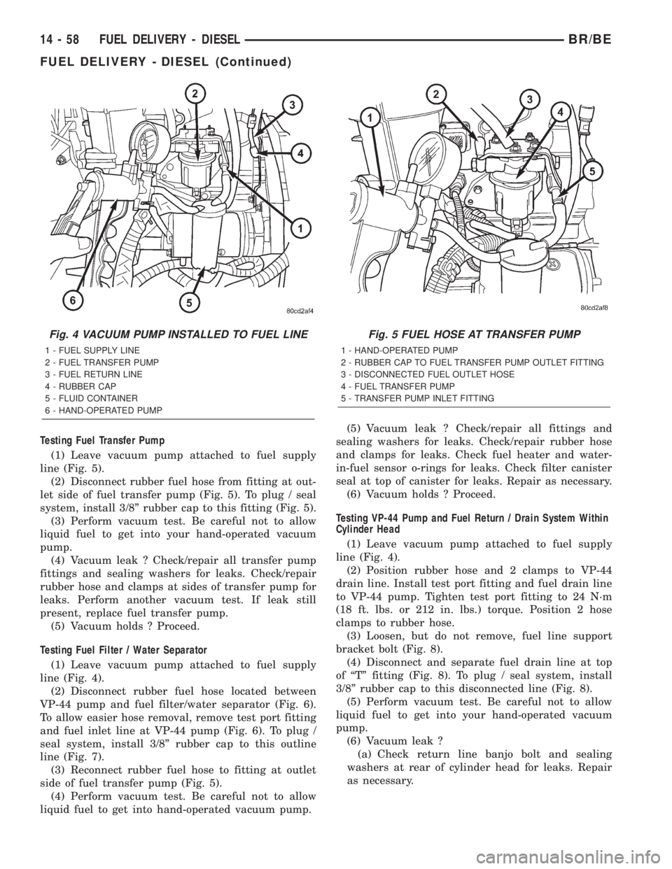
(1) Leave vacuum pump attached to fuel supply
line (Fig. 5).
(2) Disconnect rubber fuel hose from fitting at out-
let side of fuel transfer pump (Fig. 5). To plug / seal
system, install 3/8º rubber cap to this fitting (Fig. 5).
(3) Perform vacuum test. Be careful not to allow
liquid fuel to get into your hand-operated vacuum
pump.
(4) Vacuum leak ? Check/repair all transfer pump
fittings and sealing washers for leaks. Check/repair
rubber hose and clamps at sides of transfer pump for
leaks. Perform another vacuum test. If leak still
present, replace fuel transfer pump.
(5) Vacuum holds ? Proceed.
Testing Fuel Filter / Water Separator
(1) Leave vacuum pump attached to fuel supply
line (Fig. 4).
(2) Disconnect rubber fuel hose located between
VP-44 pump and fuel filter/water separator (Fig. 6).
To allow easier hose removal, remove test port fitting
and fuel inlet line at VP-44 pump (Fig. 6). To plug /
seal system, install 3/8º rubber cap to this outline
line (Fig. 7).
(3) Reconnect rubber fuel hose to fitting at outlet
side of fuel transfer pump (Fig. 5).
(4) Perform vacuum test. Be careful not to allow
liquid fuel to get into hand-operated vacuum pump.(5) Vacuum leak ? Check/repair all fittings and
sealing washers for leaks. Check/repair rubber hose
and clamps for leaks. Check fuel heater and water-
in-fuel sensor o-rings for leaks. Check filter canister
seal at top of canister for leaks. Repair as necessary.
(6) Vacuum holds ? Proceed.
Testing VP-44 Pump and Fuel Return / Drain System Within
Cylinder Head
(1) Leave vacuum pump attached to fuel supply
line (Fig. 4).
(2) Position rubber hose and 2 clamps to VP-44
drain line. Install test port fitting and fuel drain line
to VP-44 pump. Tighten test port fitting to 24 N´m
(18 ft. lbs. or 212 in. lbs.) torque. Position 2 hose
clamps to rubber hose.
(3) Loosen, but do not remove, fuel line support
bracket bolt (Fig. 8).
(4) Disconnect and separate fuel drain line at top
of ªTº fitting (Fig. 8). To plug / seal system, install
3/8º rubber cap to this disconnected line (Fig. 8).
(5) Perform vacuum test. Be careful not to allow
liquid fuel to get into your hand-operated vacuum
pump.
(6) Vacuum leak ?
(a) Check return line banjo bolt and sealing
washers at rear of cylinder head for leaks. Repair
as necessary.
Fig. 4 VACUUM PUMP INSTALLED TO FUEL LINE
1 - FUEL SUPPLY LINE
2 - FUEL TRANSFER PUMP
3 - FUEL RETURN LINE
4 - RUBBER CAP
5 - FLUID CONTAINER
6 - HAND-OPERATED PUMP
Fig. 5 FUEL HOSE AT TRANSFER PUMP
1 - HAND-OPERATED PUMP
2 - RUBBER CAP TO FUEL TRANSFER PUMP OUTLET FITTING
3 - DISCONNECTED FUEL OUTLET HOSE
4 - FUEL TRANSFER PUMP
5 - TRANSFER PUMP INLET FITTING
14 - 58 FUEL DELIVERY - DIESELBR/BE
FUEL DELIVERY - DIESEL (Continued)