2002 DODGE RAM engine oil
[x] Cancel search: engine oilPage 1123 of 2255
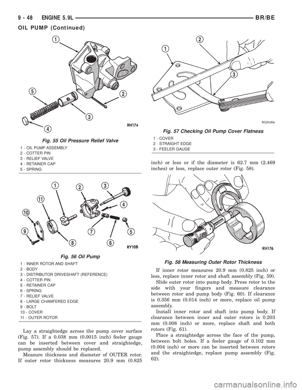
Lay a straightedge across the pump cover surface
(Fig. 57). If a 0.038 mm (0.0015 inch) feeler gauge
can be inserted between cover and straightedge,
pump assembly should be replaced.
Measure thickness and diameter of OUTER rotor.
If outer rotor thickness measures 20.9 mm (0.825inch) or less or if the diameter is 62.7 mm (2.469
inches) or less, replace outer rotor (Fig. 58).
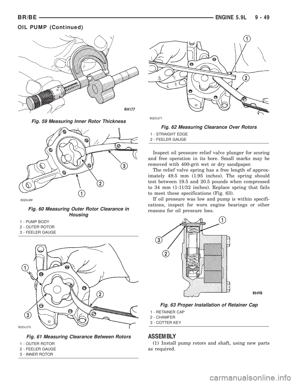
If inner rotor measures 20.9 mm (0.825 inch) or
less, replace inner rotor and shaft assembly (Fig. 59).
Slide outer rotor into pump body. Press rotor to the
side with your fingers and measure clearance
between rotor and pump body (Fig. 60). If clearance
is 0.356 mm (0.014 inch) or more, replace oil pump
assembly.
Install inner rotor and shaft into pump body. If
clearance between inner and outer rotors is 0.203
mm (0.008 inch) or more, replace shaft and both
rotors (Fig. 61).
Place a straightedge across the face of the pump,
between bolt holes. If a feeler gauge of 0.102 mm
(0.004 inch) or more can be inserted between rotors
and the straightedge, replace pump assembly (Fig.
62).
Fig. 55 Oil Pressure Relief Valve
1 - OIL PUMP ASSEMBLY
2 - COTTER PIN
3 - RELIEF VALVE
4 - RETAINER CAP
5 - SPRING
Fig. 56 Oil Pump
1 - INNER ROTOR AND SHAFT
2 - BODY
3 - DISTRIBUTOR DRIVESHAFT (REFERENCE)
4 - COTTER PIN
5 - RETAINER CAP
6 - SPRING
7 - RELIEF VALVE
8 - LARGE CHAMFERED EDGE
9 - BOLT
10 - COVER
11 - OUTER ROTOR
Fig. 57 Checking Oil Pump Cover Flatness
1 - COVER
2 - STRAIGHT EDGE
3 - FEELER GAUGE
Fig. 58 Measuring Outer Rotor Thickness
9 - 48 ENGINE 5.9LBR/BE
OIL PUMP (Continued)
Page 1124 of 2255
Inspect oil pressure relief valve plunger for scoring
and free operation in its bore. Small marks may be
removed with 400-grit wet or dry sandpaper.
The relief valve spring has a free length of approx-
imately 49.5 mm (1.95 inches). The spring should
test between 19.5 and 20.5 pounds when compressed
to 34 mm (1-11/32 inches). Replace spring that fails
to meet these specifications (Fig. 63).
If oil pressure was low and pump is within specifi-
cations, inspect for worn engine bearings or other
reasons for oil pressure loss.
ASSEMBLY
(1) Install pump rotors and shaft, using new parts
as required.
Fig. 59 Measuring Inner Rotor Thickness
Fig. 60 Measuring Outer Rotor Clearance in
Housing
1 - PUMP BODY
2 - OUTER ROTOR
3 - FEELER GAUGE
Fig. 61 Measuring Clearance Between Rotors
1 - OUTER ROTOR
2 - FEELER GAUGE
3 - INNER ROTOR
Fig. 62 Measuring Clearance Over Rotors
1 - STRAIGHT EDGE
2 - FEELER GAUGE
Fig. 63 Proper Installation of Retainer Cap
1 - RETAINER CAP
2 - CHAMFER
3 - COTTER KEY
BR/BEENGINE 5.9L 9 - 49
OIL PUMP (Continued)
Page 1125 of 2255
(2) Position the oil pump cover onto the pump
body. Tighten cover bolts to 11 N´m (95 in. lbs.)
torque.
(3) Install the relief valve and spring. Insert the
cotter pin.
(4) Tap on a new retainer cap.
(5) Prime oil pump before installation by filling
rotor cavity with engine oil.
INSTALLATION
(1) Install oil pump. During installation slowly
rotate pump body to ensure driveshaft-to-pump rotor
shaft engagement.
(2) Hold the oil pump base flush against mating
surface on No.5 main bearing cap. Finger tighten
pump attaching bolts. Tighten attaching bolts to 41
N´m (30 ft. lbs.) torque.
(3) Install the oil pan (Refer to 9 - ENGINE/LU-
BRICATION/OIL PAN - INSTALLATION).
INTAKE MANIFOLD
DESCRIPTION
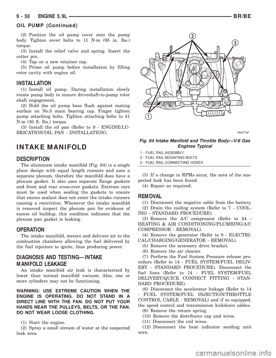
The aluminum intake manifold (Fig. 64) is a single
plane design with equal length runners and uses a
separate plenum, therefore the manifold does have a
plenum gasket. It also uses separate flange gaskets
and front and rear cross-over gaskets. Extreme care
must be used when sealing the gaskets to ensure
that excess sealant does not enter the intake runners
causing a restriction. Whenever the intake manifold
is removed inspect the plenum pan for evidence of
excess oil buildup, this condition indicates that the
plenum pan gasket is leaking.
OPERATION
The intake manifold, meters and delivers air to the
combustion chambers allowing the fuel delivered by
the fuel injectors to ignite, thus producing power.
DIAGNOSIS AND TESTINGÐINTAKE
MANIFOLD LEAKAGE
An intake manifold air leak is characterized by
lower than normal manifold vacuum. Also, one or
more cylinders may not be functioning.
WARNING: USE EXTREME CAUTION WHEN THE
ENGINE IS OPERATING. DO NOT STAND IN A
DIRECT LINE WITH THE FAN. DO NOT PUT YOUR
HANDS NEAR THE PULLEYS, BELTS, OR THE FAN.
DO NOT WEAR LOOSE CLOTHING.
(1) Start the engine.
(2) Spray a small stream of water at the suspected
leak area.(3) If a change in RPMs occur, the area of the sus-
pected leak has been found.
(4) Repair as required.
REMOVAL
(1) Disconnect the negative cable from the battery.
(2) Drain the cooling system (Refer to 7 - COOL-
ING - STANDARD PROCEDURE).
(3) Remove the A/C compressor (Refer to 24 -
HEATING & AIR CONDITIONING/PLUMBING/A/C
COMPRESSOR - REMOVAL).
(4) Remove the generator (Refer to 8 - ELECTRI-
CAL/CHARGING/GENERATOR - REMOVAL).
(5) Remove the accessory drive bracket.
(6) Remove the air cleaner.
(7) Perform the Fuel System Pressure release pro-
cedure (Refer to 14 - FUEL SYSTEM/FUEL DELIV-
ERY - STANDARD PROCEDURE). Disconnect the
fuel lines (Refer to 14 - FUEL SYSTEM/FUEL
DELIVERY/QUICK CONNECT FITTING - STAN-
DARD PROCEDURE).
(8) Disconnect the accelerator linkage (Refer to 14
- FUEL SYSTEM/FUEL INJECTION/THROTTLE
CONTROL CABLE - REMOVAL) and if so equipped,
the speed control and transmission kickdown cables.
(9) Remove the return spring.
(10) Remove the distributor cap and wires.
(11) Disconnect the coil wires.
(12) Disconnect the heat indicator sending unit
wire.
Fig. 64 Intake Manifold and Throttle BodyÐV-8 Gas
Engines Typical
1 - FUEL RAIL ASSEMBLY
2 - FUEL RAIL MOUNTING BOLTS
3 - FUEL RAIL CONNECTING HOSES
9 - 50 ENGINE 5.9LBR/BE
OIL PUMP (Continued)
Page 1127 of 2255
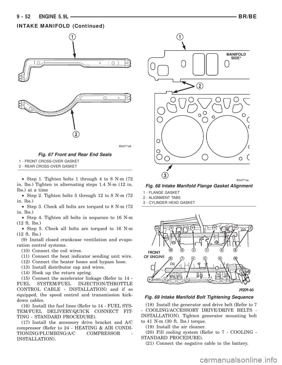
²Step 1. Tighten bolts 1 through 4 to 8 N´m (72
in. lbs.) Tighten in alternating steps 1.4 N´m (12 in.
lbs.) at a time
²Step 2. Tighten bolts 5 through 12 to 8 N´m (72
in. lbs.)
²Step 3. Check all bolts are torqued to 8 N´m (72
in. lbs.)
²Step 4. Tighten all bolts in sequence to 16 N´m
(12 ft. lbs.)
²Step 5. Check all bolts are torqued to 16 N´m
(12 ft. lbs.)
(9) Install closed crankcase ventilation and evapo-
ration control systems.
(10) Connect the coil wires.
(11) Connect the heat indicator sending unit wire.
(12) Connect the heater hoses and bypass hose.
(13) Install distributor cap and wires.
(14) Hook up the return spring.
(15) Connect the accelerator linkage (Refer to 14 -
FUEL SYSTEM/FUEL INJECTION/THROTTLE
CONTROL CABLE - INSTALLATION) and if so
equipped, the speed control and transmission kick-
down cables.
(16) Install the fuel lines (Refer to 14 - FUEL SYS-
TEM/FUEL DELIVERY/QUICK CONNECT FIT-
TING - STANDARD PROCEDURE).
(17) Install the accessory drive bracket and A/C
compressor (Refer to 24 - HEATING & AIR CONDI-
TIONING/PLUMBING/A/C COMPRESSOR -
INSTALLATION).(18) Install the generator and drive belt (Refer to 7
- COOLING/ACCESSORY DRIVE/DRIVE BELTS -
INSTALLATION). Tighten generator mounting bolt
to 41 N´m (30 ft. lbs.) torque.
(19) Install the air cleaner.
(20) Fill cooling system (Refer to 7 - COOLING -
STANDARD PROCEDURE).
(21) Connect the negative cable to the battery.
Fig. 67 Front and Rear End Seals
1 - FRONT CROSS-OVER GASKET
2 - REAR CROSS-OVER GASKET
Fig. 68 Intake Manifold Flange Gasket Alignment
1 - FLANGE GASKET
2 - ALIGNMENT TABS
3 - CYLINDER HEAD GASKET
Fig. 69 Intake Manifold Bolt Tightening Sequence
9 - 52 ENGINE 5.9LBR/BE
INTAKE MANIFOLD (Continued)
Page 1129 of 2255
(3) Remove power steering pump (Refer to 19 -
STEERING/PUMP - REMOVAL).
(4) Remove vibration damper (Refer to 9 -
ENGINE/ENGINE BLOCK/VIBRATION DAMPER -
REMOVAL).
(5) Loosen oil pan bolts and remove the front bolt
at each side.
(6) Remove the cover bolts.
(7) Remove chain case cover and gasket using
extreme caution to avoid damaging oil pan gasket.
INSTALLATION
(1) Be sure mating surfaces of chain case cover
and cylinder block are clean and free from burrs.
(2) The water pump mounting surface must be
cleaned.
(3) Using a new cover gasket, carefully install
chain case cover to avoid damaging oil pan gasket.
Use a small amount of MopartSilicone Rubber Adhe-
sive Sealant, or equivalent, at the joint between tim-
ing chain cover gasket and the oil pan gasket. Finger
tighten the timing chain cover bolts at this time.
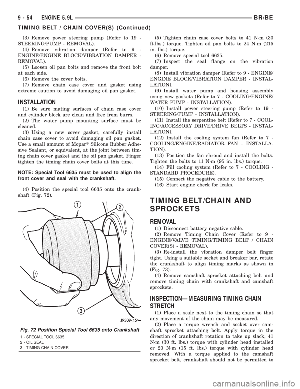
NOTE: Special Tool 6635 must be used to align the
front cover and seal with the crankshaft.
(4) Position the special tool 6635 onto the crank-
shaft (Fig. 72).(5) Tighten chain case cover bolts to 41 N´m (30
ft.lbs.) torque. Tighten oil pan bolts to 24 N´m (215
in. lbs.) torque.
(6) Remove special tool 6635.
(7) Inspect the seal flange on the vibration
damper.
(8) Install vibration damper (Refer to 9 - ENGINE/
ENGINE BLOCK/VIBRATION DAMPER - INSTAL-
LATION).
(9) Install water pump and housing assembly
using new gaskets (Refer to 7 - COOLING/ENGINE/
WATER PUMP - INSTALLATION).
(10) Install power steering pump (Refer to 19 -
STEERING/PUMP - INSTALLATION).
(11) Install the serpentine belt (Refer to 7 - COOL-
ING/ACCESSORY DRIVE/DRIVE BELTS - INSTAL-
LATION).
(12) Install the cooling system fan (Refer to 7 -
COOLING/ENGINE/RADIATOR FAN - INSTALLA-
TION).
(13) Position the fan shroud and install the bolts.
Tighten the bolts to 11 N´m (95 in. lbs.) torque.
(14) Fill cooling system (Refer to 7 - COOLING -
STANDARD PROCEDURE).
(15) Connect the negative cable to the battery.
(16) Start engine check for leaks.
TIMING BELT/CHAIN AND
SPROCKETS
REMOVAL
(1) Disconnect battery negative cable.
(2) Remove Timing Chain Cover (Refer to 9 -
ENGINE/VALVE TIMING/TIMING BELT / CHAIN
COVER(S) - REMOVAL).
(3) Re-install the vibration damper bolt finger
tight. Using a suitable socket and breaker bar, rotate
the crankshaft to align timing marks as shown in
(Fig. 73).
(4) Remove camshaft sprocket attaching bolt and
remove timing chain with crankshaft and camshaft
sprockets.
INSPECTIONÐMEASURING TIMING CHAIN
STRETCH
(1) Place a scale next to the timing chain so that
any movement of the chain may be measured.
(2) Place a torque wrench and socket over cam-
shaft sprocket attaching bolt. Apply torque in the
direction of crankshaft rotation to take up slack; 41
N´m (30 ft. lbs.) torque with cylinder head installed
or 20 N´m (15 ft. lbs.) torque with cylinder head
removed. With a torque applied to the camshaft
sprocket bolt, crankshaft should not be permitted to
Fig. 72 Position Special Tool 6635 onto Crankshaft
1 - SPECIAL TOOL 6635
2 - OIL SEAL
3 - TIMING CHAIN COVER
9 - 54 ENGINE 5.9LBR/BE
TIMING BELT / CHAIN COVER(S) (Continued)
Page 1131 of 2255
ENGINE 8.0L
TABLE OF CONTENTS
page page
ENGINE 8.0L
DESCRIPTION.........................58
DIAGNOSIS AND TESTING
DIAGNOSIS AND TESTING - ENGINE
DIAGNOSIS - INTRODUCTION...........58
DIAGNOSIS AND TESTINGÐENGINE
DIAGNOSIS - PERFORMANCE...........59
DIAGNOSIS AND TESTINGÐ ENGINE
DIAGNOSIS - MECHANICAL.............61
DIAGNOSIS AND TESTINGÐENGINE
DIAGNOSIS - LUBRICATION.............63
DIAGNOSIS AND TESTINGÐCYLINDER
COMPRESSION PRESSURE.............64
DIAGNOSIS AND TESTING - CYLINDER
COMBUSTION PRESSURE LEAKAGE......64
STANDARD PROCEDURE
STANDARD PROCEDUREÐCYLINDER
BORE HONING.......................65
STANDARD PROCEDURE - FORM-IN-
PLACE GASKETS AND SEALERS.........66
STANDARD PROCEDURE - REPAIR
DAMAGED OR WORN THREADS.........66
STANDARD PROCEDUREÐHYDROSTATIC
LOCK...............................66
REMOVAL.............................67
INSTALLATION.........................68
SPECIFICATIONS
8.OL ENGINE........................68
TORQUE............................71
SPECIAL TOOLS
8.0L ENGINE.........................72
AIR CLEANER ELEMENT
REMOVAL - 8.0L........................75
INSTALLATION - 8.0L....................75
CYLINDER HEAD
DESCRIPTION.........................76
DIAGNOSIS AND TESTINGÐCYLINDER HEAD
GASKET FAILURE.....................76
REMOVAL.............................76
CLEANING............................77
INSPECTION..........................77
INSTALLATION.........................77
CYLINDER HEAD COVER(S)
DESCRIPTION.........................78
REMOVAL.............................78
CLEANING............................79
INSPECTION..........................79
INSTALLATION.........................79INTAKE/EXHAUST VALVES & SEATS
DESCRIPTION.........................80
STANDARD PROCEDURE
VALVE SERVICE......................80
REMOVAL
REMOVALÐVALVE STEM SEALS.........82
REMOVALÐVALVES AND VALVE SPRINGS . 82
CLEANING............................83
INSPECTION..........................83
INSTALLATION
INSTALLATIONÐVALVE STEM SEAL......83
INSTALLATIONÐVALVES AND VALVE
SPRINGS............................84
ROCKER ARM / ADJUSTER ASSY
REMOVAL.............................84
INSTALLATION.........................84
ENGINE BLOCK
CLEANING............................85
INSPECTION..........................85
CAMSHAFT & BEARINGS (IN BLOCK)
REMOVAL
REMOVALÐCAMSHAFT BEARINGS.......85
REMOVALÐCAMSHAFT................85
INSTALLATION
INSTALLATIONÐCAMSHAFT BEARINGS . . . 86
INSTALLATIONÐCAMSHAFT............86
CONNECTING ROD BEARINGS
STANDARD PROCEDURE - CONNECTING
ROD BEARING FITTING................87
CRANKSHAFT
REMOVAL.............................87
INSTALLATION.........................88
CRANKSHAFT MAIN BEARINGS
STANDARD PROCEDUREÐFITTING
CRANKSHAFT MAIN BEARINGS..........88
REMOVAL.............................88
INSTALLATION.........................88
CRANKSHAFT OIL SEAL - FRONT
REMOVAL
REMOVALÐFRONT OIL SEAL - FRONT
COVER INSTALLED....................89
REMOVALÐFRONT OIL SEAL - FRONT
COVER REMOVED....................89
INSTALLATION
INSTALLATIONÐFRONT OIL SEAL ± FRONT
COVER INSTALLED....................89
INSTALLATIONÐFRONT OIL SEAL - FRONT
COVER REMOVED....................90
9 - 56 ENGINE 8.0LBR/BE
Page 1132 of 2255
CRANKSHAFT OIL SEAL - REAR
REMOVAL.............................90
INSTALLATION.........................90
CRANKSHAFT REAR OIL SEAL RETAINER
REMOVAL.............................90
INSTALLATION.........................90
HYDRAULIC LIFTERS
DIAGNOSIS AND TESTINGÐHYDRAULIC
TAPPETS............................91
REMOVAL.............................92
CLEANING............................92
INSTALLATION.........................92
PISTON & CONNECTING ROD
DESCRIPTION.........................93
STANDARD PROCEDUREÐPISTON FITTING . 93
REMOVAL.............................94
CLEANING............................94
INSPECTION..........................94
INSTALLATION.........................94
PISTON RINGS
STANDARD PROCEDUREÐFITTING PISTON
RINGS..............................95
VIBRATION DAMPER
REMOVAL.............................96
INSTALLATION.........................97
FRONT MOUNT
REMOVAL.............................97
INSTALLATION.........................98
REAR MOUNT
REMOVAL.............................98
INSTALLATION.........................98
LUBRICATION
DESCRIPTION.........................98
OPERATION...........................98
DIAGNOSIS AND TESTING
DIAGNOSIS AND TESTINGÐENGINE OIL
LEAKS..............................99
DIAGNOSIS AND TESTINGÐENGINE OIL
PRESSURE.........................101OIL
STANDARD PROCEDURE - ENGINE OIL....101
OIL FILTER
REMOVAL............................102
INSTALLATION........................102
OIL PAN
REMOVAL............................102
CLEANING...........................103
INSPECTION.........................103
INSTALLATION........................103
OIL PUMP
REMOVAL............................104
CLEANING...........................104
INSPECTION.........................104
INSTALLATION........................106
INTAKE MANIFOLD
DESCRIPTION........................106
DIAGNOSIS AND TESTINGÐINTAKE
MANIFOLD LEAKAGE.................106
REMOVAL............................107
CLEANING...........................107
INSPECTION.........................108
INSTALLATION........................108
EXHAUST MANIFOLD
DESCRIPTION........................109
OPERATION..........................109
REMOVAL............................109
CLEANING...........................109
INSPECTION.........................109
INSTALLATION........................109
TIMING BELT / CHAIN COVER(S)
REMOVAL............................110
INSTALLATION........................110
TIMING BELT/CHAIN AND SPROCKETS
REMOVAL............................111
INSPECTIONÐMEASURING TIMING CHAIN
STRETCH...........................111
INSTALLATION........................111
BR/BEENGINE 8.0L 9 - 57
Page 1133 of 2255
ENGINE 8.0L
DESCRIPTION
The 8.0 Liter (488 CID) ten-cylinder engine is a
V-Type lightweight, single cam, overhead valve
engine with hydraulic roller tappets. This engine is
designed for unleaded fuel.
Engine lubrication system consists of a gerotor
type oil pump mounted in the timing chain cover and
driven by the crankshaft. The V-10 uses a full flow
oil filter.
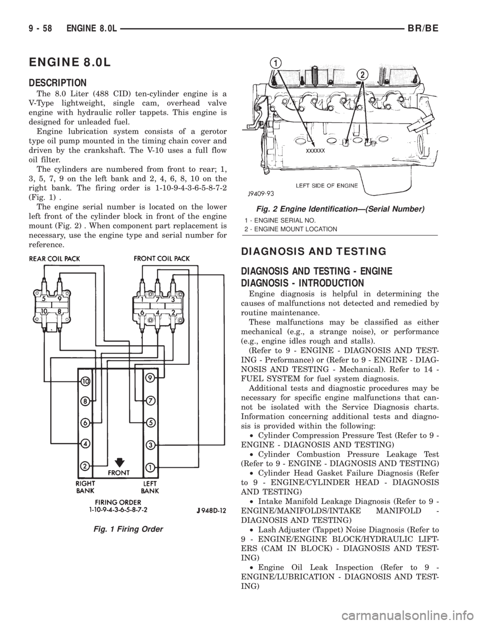
The cylinders are numbered from front to rear; 1,
3, 5, 7, 9 on the left bank and 2, 4, 6, 8, 10 on the
right bank. The firing order is 1-10-9-4-3-6-5-8-7-2
(Fig. 1) .
The engine serial number is located on the lower
left front of the cylinder block in front of the engine
mount (Fig. 2) . When component part replacement is
necessary, use the engine type and serial number for
reference.
DIAGNOSIS AND TESTING
DIAGNOSIS AND TESTING - ENGINE
DIAGNOSIS - INTRODUCTION
Engine diagnosis is helpful in determining the
causes of malfunctions not detected and remedied by
routine maintenance.
These malfunctions may be classified as either
mechanical (e.g., a strange noise), or performance
(e.g., engine idles rough and stalls).
(Refer to 9 - ENGINE - DIAGNOSIS AND TEST-
ING - Preformance) or (Refer to 9 - ENGINE - DIAG-
NOSIS AND TESTING - Mechanical). Refer to 14 -
FUEL SYSTEM for fuel system diagnosis.
Additional tests and diagnostic procedures may be
necessary for specific engine malfunctions that can-
not be isolated with the Service Diagnosis charts.
Information concerning additional tests and diagno-
sis is provided within the following:
²Cylinder Compression Pressure Test (Refer to 9 -
ENGINE - DIAGNOSIS AND TESTING)
²Cylinder Combustion Pressure Leakage Test
(Refer to 9 - ENGINE - DIAGNOSIS AND TESTING)
²Cylinder Head Gasket Failure Diagnosis (Refer
to 9 - ENGINE/CYLINDER HEAD - DIAGNOSIS
AND TESTING)
²Intake Manifold Leakage Diagnosis (Refer to 9 -
ENGINE/MANIFOLDS/INTAKE MANIFOLD -
DIAGNOSIS AND TESTING)
²Lash Adjuster (Tappet) Noise Diagnosis (Refer to
9 - ENGINE/ENGINE BLOCK/HYDRAULIC LIFT-
ERS (CAM IN BLOCK) - DIAGNOSIS AND TEST-
ING)
²Engine Oil Leak Inspection (Refer to 9 -
ENGINE/LUBRICATION - DIAGNOSIS AND TEST-
ING)
Fig. 1 Firing Order
Fig. 2 Engine IdentificationÐ(Serial Number)
1 - ENGINE SERIAL NO.
2 - ENGINE MOUNT LOCATION
9 - 58 ENGINE 8.0LBR/BE