2002 DODGE RAM warning
[x] Cancel search: warningPage 24 of 2255

TOWING WHEN KEYS ARE NOT AVAILABLE
When the vehicle is locked and keys are not avail-
able, use a flat bed hauler. A Wheel-lift or Sling-type
device can be used on 4WD vehicles providedall the
wheels are lifted off the ground using tow dol-
lies.
FOUR-WHEEL-DRIVE VEHICLE TOWING
Chrysler Corporation recommends that a vehicle be
transported on a flat-bed device. A Wheel-lift or
Sling-type device can be used providedall the
wheels are lifted off the ground using tow dol-
lies.WARNING: WHEN TOWING A DISABLED VEHICLE
AND THE DRIVE WHEELS ARE SECURED IN A
WHEEL LIFT OR TOW DOLLIES, ENSURE THE
TRANSMISSION IS IN THE PARK POSITION (AUTO-
MATIC TRANSMISSION) OR A FORWARD DRIVE
GEAR (MANUAL TRANSMISSION).
CAUTION: Many vehicles are equipped with air
dams, spoilers, and/or ground effect panels. To
avoid component damage, a wheel-lift towing vehi-
cle or a flat-bed hauling vehicle is recommended.
BR/BELUBRICATION & MAINTENANCE 0 - 11
TOWING (Continued)
Page 154 of 2255
(13) Install the fill hole plug and tighten to 34 N´m
(25 ft. lbs.).
(14) Remove support and lower vehicle.
DIFFERENTIAL - POWR-LOK
DIAGNOSIS AND TESTING - POWR-LOKT
WARNING: WHEN SERVICING VEHICLES WITH A
POWR-LOKTDIFFERENTIAL DO NOT USE THE
ENGINE TO TURN THE AXLE AND WHEELS. BOTH
REAR WHEELS MUST BE RAISED AND THE VEHI-
CLE SUPPORTED. THE AXLE CAN EXERT ENOUGH
FORCE IF ONE WHEEL IS IN CONTACT WITH A
SURFACE TO CAUSE THE VEHICLE TO MOVE.
The differential can be tested without removing the
differential case by measuring rotating torque. Make
sure brakes are not dragging during this measure-
ment.
(1) Place blocks in front and rear of both front
wheels.
(2) Raise one rear wheel until it is completely off
the ground.
(3) Engine off, transmission in neutral, and park-
ing brake off.
(4) Remove wheel and bolt Special Tool 6790 or
equivalent to wheel studs.(5) Use torque wrench on special tool to rotate
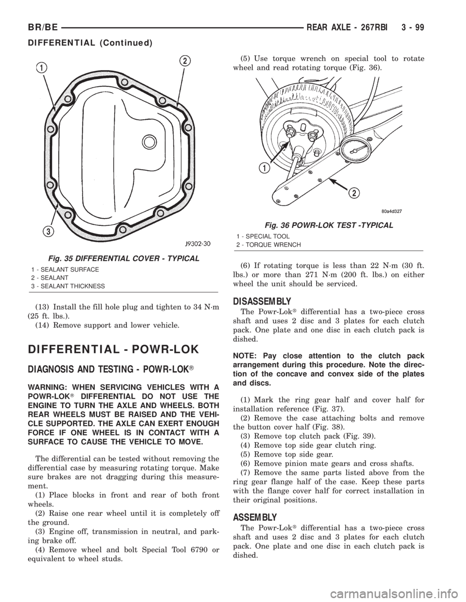
wheel and read rotating torque (Fig. 36).
(6) If rotating torque is less than 22 N´m (30 ft.
lbs.) or more than 271 N´m (200 ft. lbs.) on either
wheel the unit should be serviced.
DISASSEMBLY
The Powr-Loktdifferential has a two-piece cross
shaft and uses 2 disc and 3 plates for each clutch
pack. One plate and one disc in each clutch pack is
dished.
NOTE: Pay close attention to the clutch pack
arrangement during this procedure. Note the direc-
tion of the concave and convex side of the plates
and discs.
(1) Mark the ring gear half and cover half for
installation reference (Fig. 37).
(2) Remove the case attaching bolts and remove
the button cover half (Fig. 38).
(3) Remove top clutch pack (Fig. 39).
(4) Remove top side gear clutch ring.
(5) Remove top side gear.
(6) Remove pinion mate gears and cross shafts.
(7) Remove the same parts listed above from the
ring gear flange half of the case. Keep these parts
with the flange cover half for correct installation in
their original positions.
ASSEMBLY
The Powr-Loktdifferential has a two-piece cross
shaft and uses 2 disc and 3 plates for each clutch
pack. One plate and one disc in each clutch pack is
dished.
Fig. 35 DIFFERENTIAL COVER - TYPICAL
1 - SEALANT SURFACE
2 - SEALANT
3 - SEALANT THICKNESS
Fig. 36 POWR-LOK TEST -TYPICAL
1 - SPECIAL TOOL
2 - TORQUE WRENCH
BR/BEREAR AXLE - 267RBI 3 - 99
DIFFERENTIAL (Continued)
Page 190 of 2255
BRAKES
TABLE OF CONTENTS
page page
BRAKES - BASE........................... 1BRAKES - ABS........................... 35
BRAKES - BASE
TABLE OF CONTENTS
page page
BRAKES - BASE
SPECIFICATIONS
BASE BRAKE.........................2
TORQUE CHART......................3
SPECIAL TOOLS
BASE BRAKES........................4
HYDRAULIC/MECHANICAL
DESCRIPTION..........................4
WARNING.............................4
DIAGNOSIS AND TESTING - BASE BRAKE
SYSTEM.............................5
STANDARD PROCEDURE
STANDARD PROCEDURE - MANUAL
BLEEDING............................7
STANDARD PROCEDURE - PRESSURE
BLEEDING............................8
BRAKE LINES
STANDARD PROCEDURE
STANDARD PROCEDURE - DOUBLE
INVERTED FLARING....................8
STANDARD PROCEDURE - ISO FLARING . . . 8
COMBINATION VALVE
DESCRIPTION..........................8
OPERATION............................9
DIAGNOSIS AND TESTING - COMBINATION
VALVE ...............................9
REMOVAL.............................9
INSTALLATION..........................9
DISC BRAKE CALIPERS
DESCRIPTION.........................10
OPERATION...........................10
REMOVAL
REMOVAL - REAR.....................10
REMOVAL - FRONT....................11
DISASSEMBLY.........................11
CLEANING............................12
INSPECTION..........................12ASSEMBLY............................13
INSTALLATION
INSTALLATION - REAR.................14
INSTALLATION - FRONT................14
FLUID
DIAGNOSIS AND TESTING - BRAKE FLUID
CONTAMINATION.....................15
STANDARD PROCEDURE - BRAKE FLUID
LEVEL..............................15
SPECIFICATIONS
BRAKE FLUID........................15
FLUID RESERVOIR
REMOVAL.............................15
INSTALLATION.........................15
PEDAL
DESCRIPTION.........................17
OPERATION...........................17
REMOVAL.............................17
INSTALLATION.........................17
POWER BRAKE BOOSTER
DIAGNOSIS AND TESTING - HYDRAULIC
BOOSTER...........................18
STANDARD PROCEDURE - BLEEDING......19
REMOVAL.............................19
INSTALLATION.........................19
ROTORS
DIAGNOSIS AND TESTING
DISC BRAKE ROTOR..................20
REMOVAL
REMOVAL - REAR.....................21
REMOVAL - FRONT ± 2500..............22
REMOVAL - FRONT - 3500..............22
INSTALLATION
INSTALLATION - REAR.................22
INSTALLATION - FRONT ± 2500..........23
INSTALLATION - FRONT - 3500...........23
BR/BEBRAKES 5 - 1
Page 193 of 2255
SPECIAL TOOLS
BASE BRAKESHYDRAULIC/MECHANICAL
DESCRIPTION
This vehicle is equipped with front disc brakes and
rear drum brakes also certain vehicles have four
wheel disc brakes. The front and rear disc brakes
consist of dual piston calipers and ventilated rotors.
The rear brakes are dual brake shoe, internal
expanding units with cast brake drums. The parking
brake mechanism is cable operated and connected to
the rear brake trailing shoes. Power brake assist is
standard equipment. A vacuum operated power brake
booster is used on gas engine vehicles. A hydraulic
booster is used on diesel engine vehicles.
Two antilock brake systems are used on this vehi-
cle. A rear wheel antilock (RWAL) brake system and
all-wheel antilock brake system (ABS). The RWAL
and ABS systems are designed to retard wheel
lockup while braking. Retarding wheel lockup is
accomplished by modulating fluid pressure to the
wheel brake units. Both systems are monitored by a
microprocessor which controls the operation of the
systems.
WARNING
WARNING: DUST AND DIRT ACCUMULATING ON
BRAKE PARTS DURING NORMAL USE MAY CON-
TAIN ASBESTOS FIBERS FROM PRODUCTION OR
AFTERMARKET LININGS. BREATHING EXCESSIVE
CONCENTRATIONS OF ASBESTOS FIBERS CAN
CAUSE SERIOUS BODILY HARM. EXERCISE CARE
WHEN SERVICING BRAKE PARTS. DO NOT CLEAN
BRAKE PARTS WITH COMPRESSED AIR OR BY
DRY BRUSHING. USE A VACUUM CLEANER SPE-
CIFICALLY DESIGNED FOR THE REMOVAL OF
ASBESTOS FIBERS FROM BRAKE COMPONENTS.
IF A SUITABLE VACUUM CLEANER IS NOT AVAIL-
ABLE, CLEANING SHOULD BE DONE WITH A
WATER DAMPENED CLOTH. DO NOT SAND, OR
GRIND BRAKE LINING UNLESS EQUIPMENT USED
IS DESIGNED TO CONTAIN THE DUST RESIDUE.
DISPOSE OF ALL RESIDUE CONTAINING ASBES-
TOS FIBERS IN SEALED BAGS OR CONTAINERS
TO MINIMIZE EXPOSURE TO YOURSELF AND OTH-
ERS. FOLLOW PRACTICES PRESCRIBED BY THE
OCCUPATIONAL SAFETY AND HEALTH ADMINIS-
TRATION AND THE ENVIRONMENTAL PROTECTION
AGENCY FOR THE HANDLING, PROCESSING, AND
DISPOSITION OF DUST OR DEBRIS THAT MAY
CONTAIN ASBESTOS FIBERS.
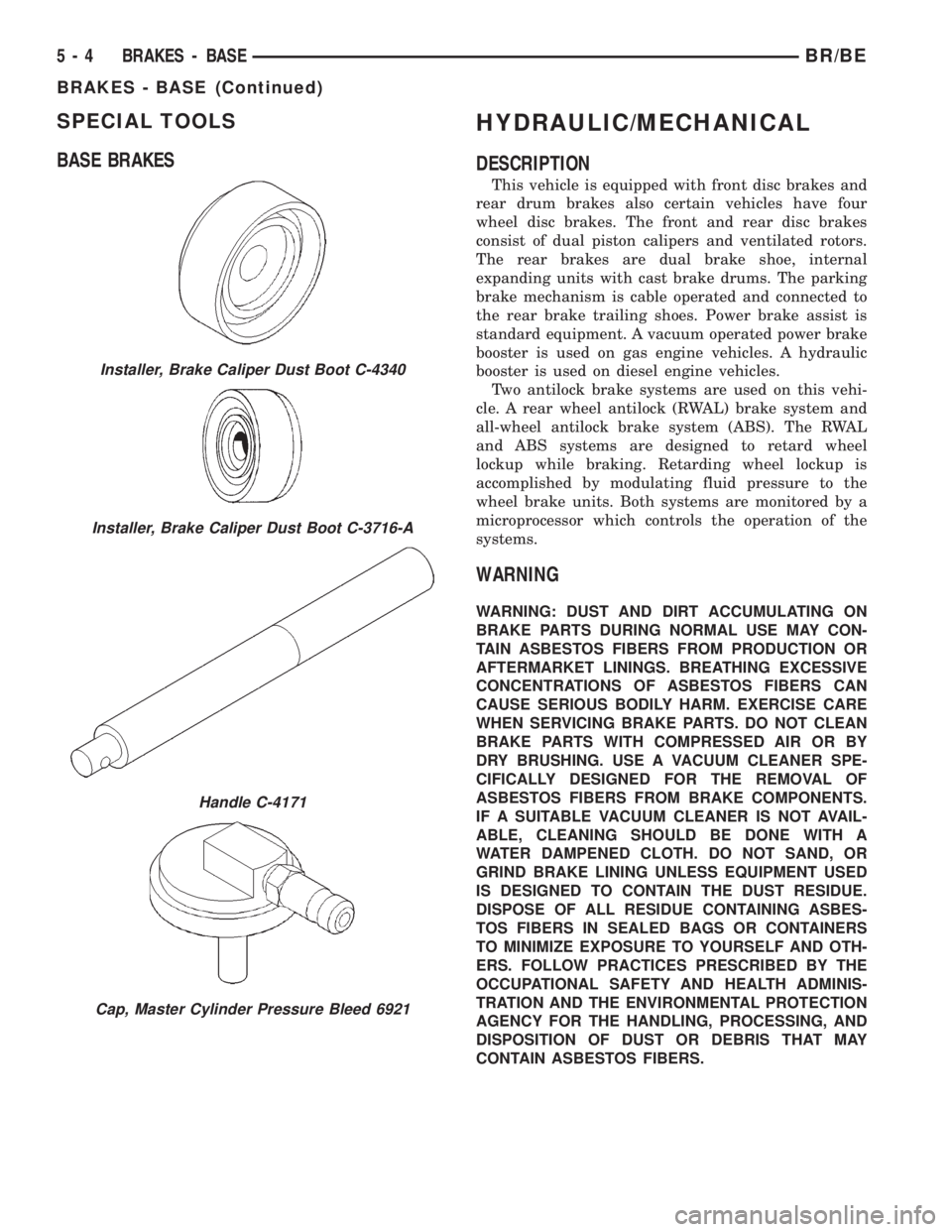
Installer, Brake Caliper Dust Boot C-4340
Installer, Brake Caliper Dust Boot C-3716-A
Handle C-4171
Cap, Master Cylinder Pressure Bleed 6921
5 - 4 BRAKES - BASEBR/BE
BRAKES - BASE (Continued)
Page 197 of 2255
STANDARD PROCEDURE - PRESSURE
BLEEDING
Use Mopar brake fluid, or an equivalent quality
fluid meeting SAE J1703-F and DOT 3 standards
only. Use fresh, clean fluid from a sealed container at
all times.
If pressure bleeding equipment will be used, the
front brake metering valve will have to be held open
to bleed the front brakes. The valve stem is located
in the forward end or top of the combination valve.
The stem must either be pressed inward, or held out-
ward slightly. A spring clip tool or helper is needed to
hold the valve stem in position.
Follow the manufacturers instructions carefully
when using pressure equipment. Do not exceed the
tank manufacturers pressure recommendations. Gen-
erally, a tank pressure of 15-20 psi is sufficient for
bleeding.
Fill the bleeder tank with recommended fluid and
purge air from the tank lines before bleeding.
Do not pressure bleed without a proper master cyl-
inder adapter. The wrong adapter can lead to leak-
age, or drawing air back into the system. Use
adapter provided with the equipment or Adapter
6921.
BRAKE LINES
STANDARD PROCEDURE
STANDARD PROCEDURE - DOUBLE INVERTED
FLARING
A preformed metal brake tube is recommended and
preferred for all repairs. However, double-wall steel
tube can be used for emergency repair when factory
replacement parts are not readily available.
(1) Cut off damaged tube with Tubing Cutter.
(2) Ream cut edges of tubing to ensure proper
flare.
(3) Install replacement tube nut on the tube.
(4) Insert tube in flaring tool.
(5) Place gauge form over the end of the tube.
(6) Push tubing through flaring tool jaws until
tube contacts recessed notch in gauge that matches
tube diameter.
(7) Tighten the tool bar on the tube
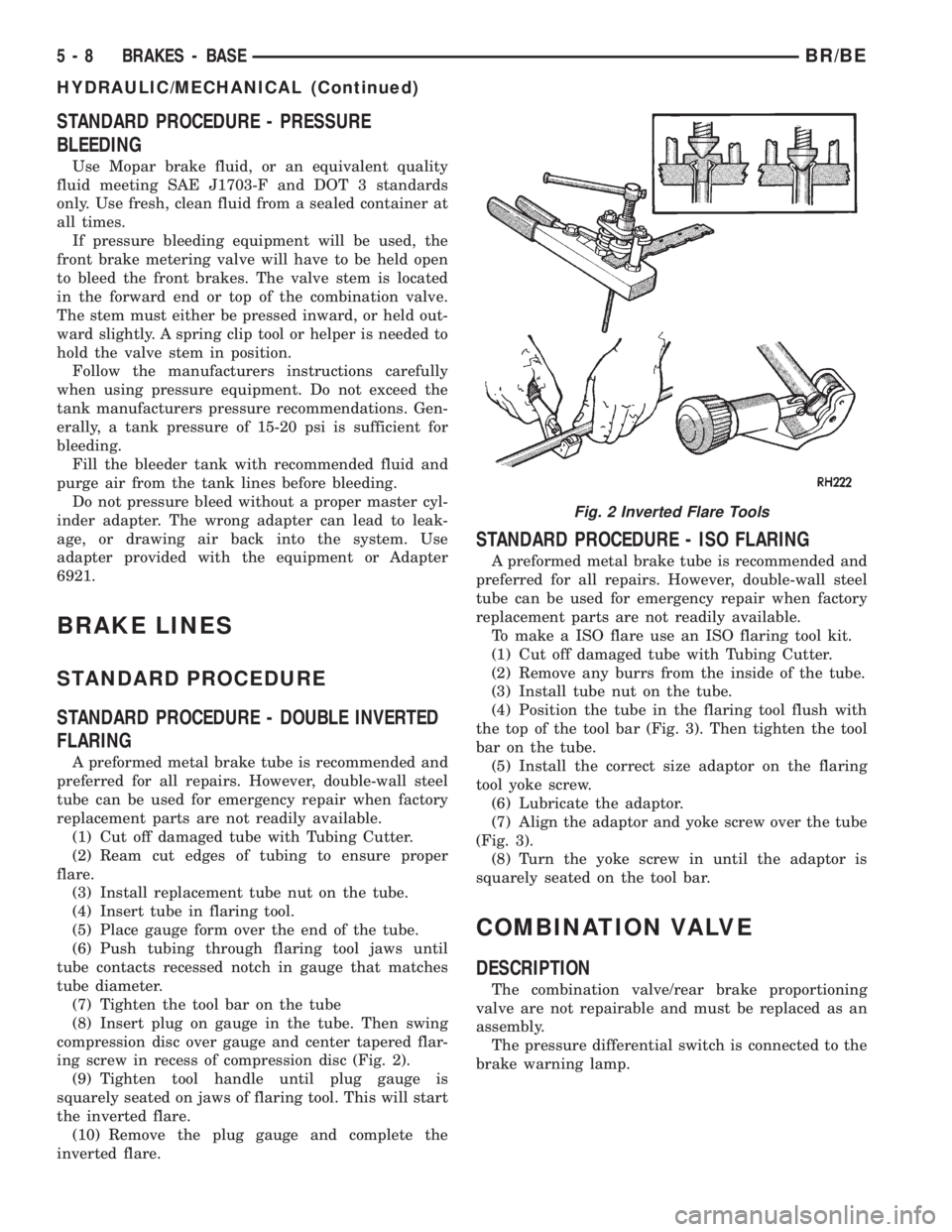
(8) Insert plug on gauge in the tube. Then swing
compression disc over gauge and center tapered flar-
ing screw in recess of compression disc (Fig. 2).
(9) Tighten tool handle until plug gauge is
squarely seated on jaws of flaring tool. This will start
the inverted flare.
(10) Remove the plug gauge and complete the
inverted flare.
STANDARD PROCEDURE - ISO FLARING
A preformed metal brake tube is recommended and
preferred for all repairs. However, double-wall steel
tube can be used for emergency repair when factory
replacement parts are not readily available.
To make a ISO flare use an ISO flaring tool kit.
(1) Cut off damaged tube with Tubing Cutter.
(2) Remove any burrs from the inside of the tube.
(3) Install tube nut on the tube.
(4) Position the tube in the flaring tool flush with
the top of the tool bar (Fig. 3). Then tighten the tool
bar on the tube.
(5) Install the correct size adaptor on the flaring
tool yoke screw.
(6) Lubricate the adaptor.
(7) Align the adaptor and yoke screw over the tube
(Fig. 3).
(8) Turn the yoke screw in until the adaptor is
squarely seated on the tool bar.
COMBINATION VALVE
DESCRIPTION
The combination valve/rear brake proportioning
valve are not repairable and must be replaced as an
assembly.
The pressure differential switch is connected to the
brake warning lamp.
Fig. 2 Inverted Flare Tools
5 - 8 BRAKES - BASEBR/BE
HYDRAULIC/MECHANICAL (Continued)
Page 198 of 2255

OPERATION
PRESSURE DIFFERENTIAL SWITCH
The switch is triggered by movement of the switch
valve. The purpose of the switch is to monitor fluid
pressure in the separate front/rear brake hydraulic
circuits.
A decrease or loss of fluid pressure in either
hydraulic circuit will cause the switch valve to shut-
tle forward or rearward in response to the pressure
differential. Movement of the switch valve will push
the switch plunger upward. This closes the switch
internal contacts completing the electrical circuit to
the warning lamp. The switch valve may remain in
an actuated position until repair restores system
pressures to normal levels.
DIAGNOSIS AND TESTING - COMBINATION
VALVE
Pressure Differential Switch
(1) Have helper sit in drivers seat to apply brake
pedal and observe red brake warning light.
(2) Raise vehicle on hoist.(3) Connect bleed hose to a rear wheel cylinder
and immerse hose end in container partially filled
with brake fluid.
(4) Have helper press and hold brake pedal to floor
and observe warning light.
(a) If warning light illuminates, switch is operat-
ing correctly.
(b) If light fails to illuminate, check circuit fuse,
bulb, and wiring. The parking brake switch can be
used to aid in identifying whether or not the brake
light bulb and fuse is functional. Repair or replace
parts as necessary and test differential pressure
switch operation again.
(5) If warning light still does not illuminate,
switch is faulty. Replace combination valve assembly,
bleed brake system and verify proper switch and
valve operation.
REMOVAL
(1) Remove pressure differential switch wire con-
nector (Fig. 4) from the valve.
(2) Remove the brake lines from the valve.
(3) Remove the valve mounting bolt and remove
the valve from the bracket.
INSTALLATION
(1) Position the valve on the bracket and install
the mounting bolt. Tighten the mounting bolt to 23
N´m (210 in. lbs.).
(2) Install the brake lines into the valve and
tighten to 19-23 N´m (170-200 in. lbs.).
Fig. 3 ISO Flaring
1 - ADAPTER
2 - LUBRICATE HERE
3 - PILOT
4 - FLUSH WITH BAR
5 - TUBING
6 - BAR ASSEMBLY
Fig. 4 Pressure
1 - COMBINATION VALVE
2 - BRAKE LINES
3 - MOUNTING BOLT
4 - PRESSURE DIFFERENTIAL SWITCH
BR/BEBRAKES - BASE 5 - 9
COMBINATION VALVE (Continued)
Page 201 of 2255
CAUTION: Do not blow the piston out of the bore
with sustained air pressure. This could result in a
cracked piston.
WARNING: NEVER ATTEMPT TO CATCH THE PIS-
TON AS IT LEAVES THE BORE. THIS COULD
RESULT IN PERSONAL INJURY.
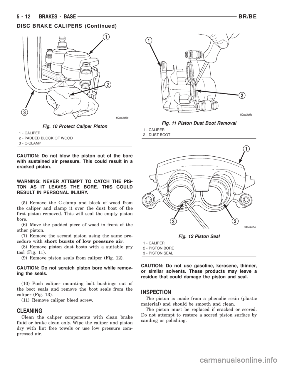
(5) Remove the C-clamp and block of wood from
the caliper and clamp it over the dust boot of the
first piston removed. This will seal the empty piston
bore.
(6) Move the padded piece of wood in front of the
other piston.
(7) Remove the second piston using the same pro-
cedure withshort bursts of low pressure air.
(8) Remove piston dust boots with a suitable pry
tool (Fig. 11).
(9) Remove piston seals from caliper (Fig. 12).
CAUTION: Do not scratch piston bore while remov-
ing the seals.
(10) Push caliper mounting bolt bushings out of
the boot seals and remove the boot seals from the
caliper (Fig. 13).
(11) Remove caliper bleed screw.
CLEANING
Clean the caliper components with clean brake
fluid or brake clean only. Wipe the caliper and piston
dry with lint free towels or use low pressure com-
pressed air.CAUTION: Do not use gasoline, kerosene, thinner,
or similar solvents. These products may leave a
residue that could damage the piston and seal.
INSPECTION
The piston is made from a phenolic resin (plastic
material) and should be smooth and clean.
The piston must be replaced if cracked or scored.
Do not attempt to restore a scored piston surface by
sanding or polishing.
Fig. 10 Protect Caliper Piston
1 - CALIPER
2 - PADDED BLOCK OF WOOD
3 - C-CLAMP
Fig. 11 Piston Dust Boot Removal
1 - CALIPER
2 - DUST BOOT
Fig. 12 Piston Seal
1 - CALIPER
2 - PISTON BORE
3 - PISTON SEAL
5 - 12 BRAKES - BASEBR/BE
DISC BRAKE CALIPERS (Continued)
Page 208 of 2255
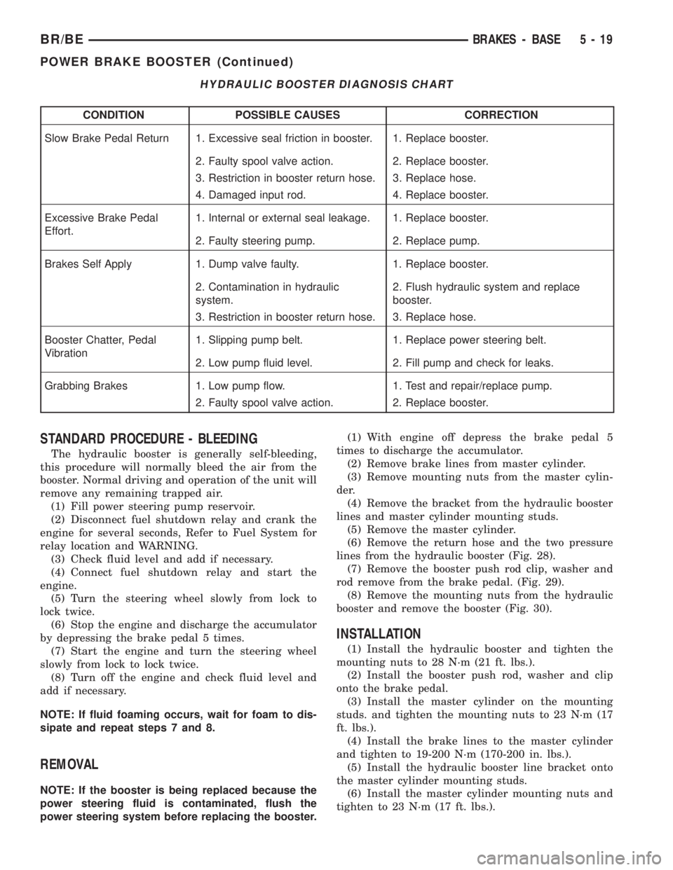
HYDRAULIC BOOSTER DIAGNOSIS CHART
CONDITION POSSIBLE CAUSES CORRECTION
Slow Brake Pedal Return 1. Excessive seal friction in booster. 1. Replace booster.
2. Faulty spool valve action. 2. Replace booster.
3. Restriction in booster return hose. 3. Replace hose.
4. Damaged input rod. 4. Replace booster.
Excessive Brake Pedal
Effort.1. Internal or external seal leakage. 1. Replace booster.
2. Faulty steering pump. 2. Replace pump.
Brakes Self Apply 1. Dump valve faulty. 1. Replace booster.
2. Contamination in hydraulic
system.2. Flush hydraulic system and replace
booster.
3. Restriction in booster return hose. 3. Replace hose.
Booster Chatter, Pedal
Vibration1. Slipping pump belt. 1. Replace power steering belt.
2. Low pump fluid level. 2. Fill pump and check for leaks.
Grabbing Brakes 1. Low pump flow. 1. Test and repair/replace pump.
2. Faulty spool valve action. 2. Replace booster.
STANDARD PROCEDURE - BLEEDING
The hydraulic booster is generally self-bleeding,
this procedure will normally bleed the air from the
booster. Normal driving and operation of the unit will
remove any remaining trapped air.
(1) Fill power steering pump reservoir.
(2) Disconnect fuel shutdown relay and crank the
engine for several seconds, Refer to Fuel System for
relay location and WARNING.
(3) Check fluid level and add if necessary.
(4) Connect fuel shutdown relay and start the
engine.
(5) Turn the steering wheel slowly from lock to
lock twice.
(6) Stop the engine and discharge the accumulator
by depressing the brake pedal 5 times.
(7) Start the engine and turn the steering wheel
slowly from lock to lock twice.
(8) Turn off the engine and check fluid level and
add if necessary.
NOTE: If fluid foaming occurs, wait for foam to dis-
sipate and repeat steps 7 and 8.
REMOVAL
NOTE: If the booster is being replaced because the
power steering fluid is contaminated, flush the
power steering system before replacing the booster.(1) With engine off depress the brake pedal 5
times to discharge the accumulator.
(2) Remove brake lines from master cylinder.
(3) Remove mounting nuts from the master cylin-
der.
(4) Remove the bracket from the hydraulic booster
lines and master cylinder mounting studs.
(5) Remove the master cylinder.
(6) Remove the return hose and the two pressure
lines from the hydraulic booster (Fig. 28).
(7) Remove the booster push rod clip, washer and
rod remove from the brake pedal. (Fig. 29).
(8) Remove the mounting nuts from the hydraulic
booster and remove the booster (Fig. 30).
INSTALLATION
(1) Install the hydraulic booster and tighten the
mounting nuts to 28 N´m (21 ft. lbs.).
(2) Install the booster push rod, washer and clip
onto the brake pedal.
(3) Install the master cylinder on the mounting
studs. and tighten the mounting nuts to 23 N´m (17
ft. lbs.).
(4) Install the brake lines to the master cylinder
and tighten to 19-200 N´m (170-200 in. lbs.).
(5) Install the hydraulic booster line bracket onto
the master cylinder mounting studs.
(6) Install the master cylinder mounting nuts and
tighten to 23 N´m (17 ft. lbs.).
BR/BEBRAKES - BASE 5 - 19
POWER BRAKE BOOSTER (Continued)