2002 DODGE RAM warning
[x] Cancel search: warningPage 542 of 2255

(3) If the multi-function switch fails any of the
continuity or resistance tests, replace the faulty
switch unit as required.
REMOVAL
WARNING: ON VEHICLES EQUIPPED WITH AIR-
BAGS, DISABLE THE AIRBAG SYSTEM BEFORE
ATTEMPTING ANY STEERING WHEEL, STEERING
COLUMN, OR INSTRUMENT PANEL COMPONENT
DIAGNOSIS OR SERVICE. DISCONNECT AND ISO-
LATE THE BATTERY NEGATIVE (GROUND) CABLE,
THEN WAIT TWO MINUTES FOR THE AIRBAG SYS-
TEM CAPACITOR TO DISCHARGE BEFORE PER-
FORMING FURTHER DIAGNOSIS OR SERVICE. THIS
IS THE ONLY SURE WAY TO DISABLE THE AIRBAG
SYSTEM. FAILURE TO TAKE THE PROPER PRE-
CAUTIONS COULD RESULT IN ACCIDENTAL AIR-
BAG DEPLOYMENT AND POSSIBLE PERSONAL
INJURY.
(1) Disconnect and isolate the battery negative
cable.
(2) If the vehicle is so equipped, unscrew the lever
from the tilt steering column adjuster mechanism
located on the left side of the column just below the
multi-function switch control stalk. Turn the lever
counterclockwise to unscrew it from the adjuster.
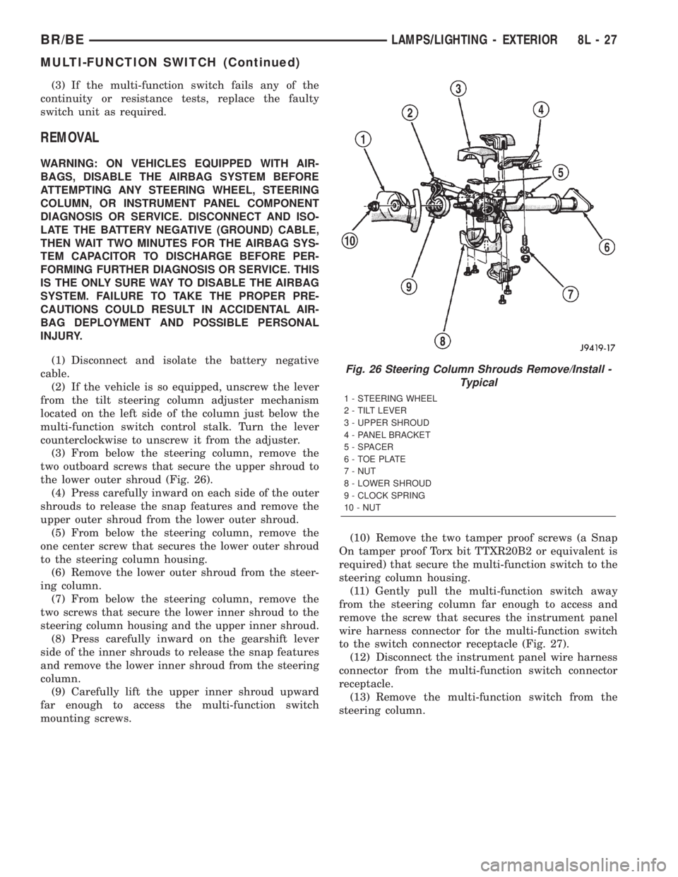
(3) From below the steering column, remove the
two outboard screws that secure the upper shroud to
the lower outer shroud (Fig. 26).
(4) Press carefully inward on each side of the outer
shrouds to release the snap features and remove the
upper outer shroud from the lower outer shroud.
(5) From below the steering column, remove the
one center screw that secures the lower outer shroud
to the steering column housing.
(6) Remove the lower outer shroud from the steer-
ing column.
(7) From below the steering column, remove the
two screws that secure the lower inner shroud to the
steering column housing and the upper inner shroud.
(8) Press carefully inward on the gearshift lever
side of the inner shrouds to release the snap features
and remove the lower inner shroud from the steering
column.
(9) Carefully lift the upper inner shroud upward
far enough to access the multi-function switch
mounting screws.(10) Remove the two tamper proof screws (a Snap
On tamper proof Torx bit TTXR20B2 or equivalent is
required) that secure the multi-function switch to the
steering column housing.
(11) Gently pull the multi-function switch away
from the steering column far enough to access and
remove the screw that secures the instrument panel
wire harness connector for the multi-function switch
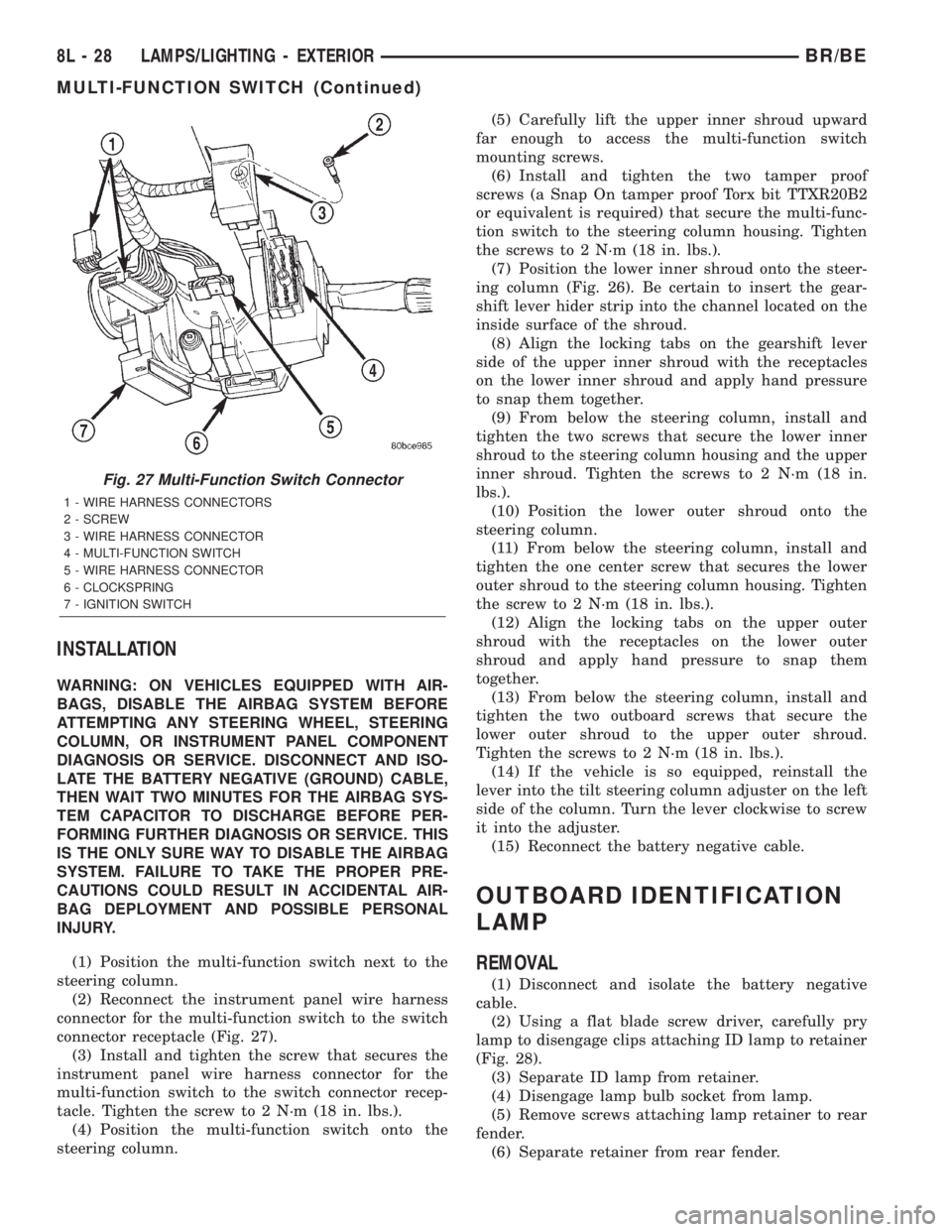
to the switch connector receptacle (Fig. 27).
(12) Disconnect the instrument panel wire harness
connector from the multi-function switch connector
receptacle.
(13) Remove the multi-function switch from the
steering column.
Fig. 26 Steering Column Shrouds Remove/Install -
Typical
1 - STEERING WHEEL
2 - TILT LEVER
3 - UPPER SHROUD
4 - PANEL BRACKET
5 - SPACER
6 - TOE PLATE
7 - NUT
8 - LOWER SHROUD
9 - CLOCK SPRING
10 - NUT
BR/BELAMPS/LIGHTING - EXTERIOR 8L - 27
MULTI-FUNCTION SWITCH (Continued)
Page 543 of 2255

INSTALLATION
WARNING: ON VEHICLES EQUIPPED WITH AIR-
BAGS, DISABLE THE AIRBAG SYSTEM BEFORE
ATTEMPTING ANY STEERING WHEEL, STEERING
COLUMN, OR INSTRUMENT PANEL COMPONENT
DIAGNOSIS OR SERVICE. DISCONNECT AND ISO-
LATE THE BATTERY NEGATIVE (GROUND) CABLE,
THEN WAIT TWO MINUTES FOR THE AIRBAG SYS-
TEM CAPACITOR TO DISCHARGE BEFORE PER-
FORMING FURTHER DIAGNOSIS OR SERVICE. THIS
IS THE ONLY SURE WAY TO DISABLE THE AIRBAG
SYSTEM. FAILURE TO TAKE THE PROPER PRE-
CAUTIONS COULD RESULT IN ACCIDENTAL AIR-
BAG DEPLOYMENT AND POSSIBLE PERSONAL
INJURY.
(1) Position the multi-function switch next to the
steering column.
(2) Reconnect the instrument panel wire harness
connector for the multi-function switch to the switch
connector receptacle (Fig. 27).
(3) Install and tighten the screw that secures the
instrument panel wire harness connector for the
multi-function switch to the switch connector recep-
tacle. Tighten the screw to 2 N´m (18 in. lbs.).
(4) Position the multi-function switch onto the
steering column.(5) Carefully lift the upper inner shroud upward
far enough to access the multi-function switch
mounting screws.
(6) Install and tighten the two tamper proof
screws (a Snap On tamper proof Torx bit TTXR20B2
or equivalent is required) that secure the multi-func-
tion switch to the steering column housing. Tighten
the screws to 2 N´m (18 in. lbs.).
(7) Position the lower inner shroud onto the steer-
ing column (Fig. 26). Be certain to insert the gear-
shift lever hider strip into the channel located on the
inside surface of the shroud.
(8) Align the locking tabs on the gearshift lever
side of the upper inner shroud with the receptacles
on the lower inner shroud and apply hand pressure
to snap them together.
(9) From below the steering column, install and
tighten the two screws that secure the lower inner
shroud to the steering column housing and the upper
inner shroud. Tighten the screws to 2 N´m (18 in.
lbs.).
(10) Position the lower outer shroud onto the
steering column.
(11) From below the steering column, install and
tighten the one center screw that secures the lower
outer shroud to the steering column housing. Tighten
the screw to 2 N´m (18 in. lbs.).
(12) Align the locking tabs on the upper outer
shroud with the receptacles on the lower outer
shroud and apply hand pressure to snap them
together.
(13) From below the steering column, install and
tighten the two outboard screws that secure the
lower outer shroud to the upper outer shroud.
Tighten the screws to 2 N´m (18 in. lbs.).
(14) If the vehicle is so equipped, reinstall the
lever into the tilt steering column adjuster on the left
side of the column. Turn the lever clockwise to screw
it into the adjuster.
(15) Reconnect the battery negative cable.
OUTBOARD IDENTIFICATION
LAMP
REMOVAL
(1) Disconnect and isolate the battery negative
cable.
(2) Using a flat blade screw driver, carefully pry
lamp to disengage clips attaching ID lamp to retainer
(Fig. 28).
(3) Separate ID lamp from retainer.
(4) Disengage lamp bulb socket from lamp.
(5) Remove screws attaching lamp retainer to rear
fender.
(6) Separate retainer from rear fender.
Fig. 27 Multi-Function Switch Connector
1 - WIRE HARNESS CONNECTORS
2 - SCREW
3 - WIRE HARNESS CONNECTOR
4 - MULTI-FUNCTION SWITCH
5 - WIRE HARNESS CONNECTOR
6 - CLOCKSPRING
7 - IGNITION SWITCH
8L - 28 LAMPS/LIGHTING - EXTERIORBR/BE
MULTI-FUNCTION SWITCH (Continued)
Page 548 of 2255

LAMPS/LIGHTING - INTERIOR
TABLE OF CONTENTS
page page
LAMPS/LIGHTING - INTERIOR
SPECIFICATIONS
INTERIOR LAMPS.....................33
DOME LAMP
REMOVAL.............................34
INSTALLATION.........................34
DOOR AJAR SWITCH
DESCRIPTION.........................34
DIAGNOSIS AND TESTING - DOOR AJAR
SWITCH............................34
REMOVAL.............................35
INSTALLATION.........................35GLOVE BOX LAMP AND SWITCH
REMOVAL.............................35
INSTALLATION.........................36
READING LAMP
DESCRIPTION.........................36
OPERATION...........................36
REMOVAL.............................36
INSTALLATION.........................37
VANITY LAMP
REMOVAL.............................37
INSTALLATION.........................37
LAMPS/LIGHTING - INTERIOR
SPECIFICATIONS
INTERIOR LAMPS
LAMP BULB
A/C HEATER CONTROL 158
ASH RECEIVER 161
CIGAR LIGHTER 161
HEADLAMP SWITCH 158
HEATER CONTROL 158
INSTRUMENT CLUSTER PC194
RADIO ASC
AIRBAG HIGH LINE PC194
AIRBAG LOW LINE PC74
ANTI-LOCK BRAKE PC74
BATTERY VOLTAGE PC194
BRAKE WARNING PC194LAMP BULB
CHECK ENGINE PC74
ENGINE OIL PRESSURE PC74
FOUR WHEEL DRIVE PC194
HIGH BEAM PC194
LOW FUEL PC194
LOW WASHER FLUID PC74
MAINTENANCE
REQUIREDPC74
MESSAGE CENTER PC194
SEAT BELT PC74
TURN SIGNAL PC194
UPSHIFT PC74
DOME 1004
GLOVE COMPARTMENT 1891
VANITY MIRROR LAMP P/N 6501966
BR/BELAMPS/LIGHTING - INTERIOR 8L - 33
Page 549 of 2255

DOME LAMP
REMOVAL
(1) Using a small flat blade, pry the left side (driv-
er's side) of the dome lamp lens downward from
dome lamp.
(2) Allow the lens to hang down (Fig. 1) , this will
disengage the right side of the lamp (passenger's
side) from the headliner.
(3) Pull the right side of the lamp down and slide
the lamp to the right (Fig. 2) .
(4) Separate the lamp from the headliner.
(5) Disengage dome lamp wire connector from body
wire harness.
(6) Separate dome lamp from vehicle.
INSTALLATION
(1) Position dome lamp at headliner.
(2) Connect dome lamp wire connector to body
wire harness.
(3) Position the left side of the lamp in the head-
liner opening and slide lamp to the left.
(4) Push the right side of the lamp in the head-
liner opening and push the lamp lens up into the
lamp to secure.
DOOR AJAR SWITCH
DESCRIPTION
The door ajar switches are mounted to the door
hinge pillars. The switches close a path to ground for
the Central Timer Module (CTM) when a door is
opened, and open the ground path when a door is
closed.
The door ajar switches cannot be repaired and, if
faulty or damaged, they must be replaced.
DIAGNOSIS AND TESTING - DOOR AJAR
SWITCH
For circuit descriptions and diagrams, refer to the
appropriate wiring information. The wiring informa-
tion includes wiring diagrams, proper wire and con-
nector repair procedures, details of wire harness
routing and retention, connector pin-out information
and location views for the various wire harness con-
nectors, splices and grounds.
WARNING: ON VEHICLES EQUIPPED WITH AIR-
BAGS, REFER TO ELECTRICAL, RESTRAINTS
BEFORE ATTEMPTING ANY STEERING WHEEL,
STEERING COLUMN, OR INSTRUMENT PANEL
COMPONENT DIAGNOSIS OR SERVICE. FAILURE
TO TAKE THE PROPER PRECAUTIONS COULD
RESULT IN ACCIDENTAL AIRBAG DEPLOYMENT
AND POSSIBLE PERSONAL INJURY.
(1) Rotate the headlamp switch knob counterclock-
wise to ensure that the dome lamps are not switched
off. Open the driver door and note whether the inte-
rior lamps light. They should light. If OK, (Refer to 8
- ELECTRICAL/LAMPS/LIGHTING - EXTERIOR/
HEADLAMP SWITCH - DIAGNOSIS AND TEST-
ING). If not OK, go to Step 2.
(2) Disconnect and isolate the battery negative
cable. Unplug the driver door ajar switch from its
wire harness connector. Check for continuity between
the ground circuit cavity of the driver door ajar
switch wire harness connector and a good ground.
There should be continuity. If OK, go to Step 3. If not
OK, repair the circuit to ground as required.
Fig. 1 Dome Lamp Lens
1 - HEADLINER
2 - CONNECTOR
3 - DOME LAMP
4 - LENS
5 - BULB
Fig. 2 Dome Lamp
1 - SLIDE LAMP
8L - 34 LAMPS/LIGHTING - INTERIORBR/BE
Page 594 of 2255

RESTRAINTS
TABLE OF CONTENTS
page page
RESTRAINTS
DESCRIPTION..........................1
OPERATION............................2
WARNING.............................3
DIAGNOSIS AND TESTING - AIRBAG SYSTEM . 4
STANDARD PROCEDURE
STANDARD PROCEDURE - HANDLING
NON-DEPLOYED AIRBAGS...............4
STANDARD PROCEDURE - SERVICE
AFTER AN AIRBAG DEPLOYMENT.........4
STANDARD PROCEDURE - VERIFICATION
TEST................................5
SPECIAL TOOLS - AIRBAG SYSTEM.........6
AIRBAG CONTROL MODULE
DESCRIPTION..........................6
OPERATION............................6
REMOVAL.............................7
INSTALLATION..........................8
CHILD TETHER
REMOVAL.............................9
INSTALLATION..........................9
CLOCKSPRING
DESCRIPTION.........................10
OPERATION...........................10
STANDARD PROCEDURE - CLOCKSPRING
CENTERING.........................11
REMOVAL.............................12
INSTALLATION.........................13
DRIVER AIRBAG
DESCRIPTION.........................14
OPERATION...........................14
REMOVAL.............................14
DISASSEMBLY.........................15
ASSEMBLY............................16
INSTALLATION.........................17
FRONT SEAT BELT & RETRACTOR
REMOVAL
REMOVAL - STANDARD CAB............18REMOVAL - CLUB/QUAD CAB............19
INSTALLATION
INSTALLATION - STANDARD CAB.........19
INSTALLATION - CLUB/QUAD CAB........20
FRONT SEAT BELT BUCKLE
REMOVAL.............................20
INSTALLATION.........................20
PASSENGER AIRBAG
DESCRIPTION.........................21
OPERATION...........................21
REMOVAL.............................21
INSTALLATION.........................23
PASSENGER AIRBAG ON/OFF SWITCH
DESCRIPTION.........................23
OPERATION...........................24
REMOVAL.............................24
INSTALLATION.........................25
REAR SEAT BELT & RETRACTOR
REMOVAL.............................26
INSTALLATION.........................26
REAR SEAT BELT BUCKLE
REMOVAL.............................27
INSTALLATION.........................27
SEAT BELT SWITCH
DESCRIPTION.........................28
OPERATION...........................28
DIAGNOSIS AND TESTING - SEAT BELT
SWITCH............................28
SEAT BELT TURNING LOOP ADJUSTER
REMOVAL.............................29
INSTALLATION.........................29
TURNING LOOP HGT ADJUSTER KNOB
REMOVAL.............................30
INSTALLATION.........................30
RESTRAINTS
DESCRIPTION
A dual front airbag system is standard factory-in-
stalled safety equipment on this model. The airbag
system is a passive, inflatable, Supplemental
Restraint System (SRS) and vehicles with this equip-
ment can be readily identified by the ªSRS - AIR-
BAGº logo molded into the driver airbag trim coverin the center of the steering wheel and also into the
passenger airbag door on the instrument panel above
the glove box (Fig. 1). Vehicles with the airbag sys-
tem can also be identified by the airbag indicator,
which will illuminate in the instrument cluster for
about seven seconds as a bulb test each time the
ignition switch is turned to the On position.
The dual front airbag system consists of the follow-
ing major components, which are described in further
detail elsewhere in this service manual:
BR/BERESTRAINTS 8O - 1
Page 596 of 2255

circumstances necessitate that a child, or an adult
with certain medical conditions be placed in the front
passenger seating position. Refer to the owner's man-
ual in the vehicle glove box for specific recommenda-
tions concerning the specific circumstances where the
passenger airbag on/off switch should be used to dis-
able the passenger airbag.
Deployment of the airbags depends upon the angle
and severity of the impact. The airbag system is
designed to deploy upon a frontal impact within a
thirty degree angle from either side of the vehicle
center line. Deployment is not based upon vehicle
speed; rather, deployment is based upon the rate of
deceleration as measured by the forces of gravity (G
force) upon the airbag system impact sensor, which is
integral to the ACM. When a frontal impact is severe
enough, the microprocessor in the ACM signals the
inflator units of both airbag modules to deploy the
airbags. During a frontal vehicle impact, the knee
blockers work in concert with properly fastened and
adjusted seat belts to restrain both the driver and
the front seat passenger in the proper position for an
airbag deployment. The knee blockers also absorb
and distribute the crash energy from the driver and
the front seat passenger to the structure of the
instrument panel.
Typically, the driver and front seat passenger recall
more about the events preceding and following a col-
lision than they have of the airbag deployment itself.
This is because the airbag deployment and deflation
occur so rapidly. In a typical 48 kilometer-per-hour
(30 mile-per-hour) barrier impact, from the moment
of impact until both airbags are fully inflated takes
about 40 milliseconds. Within one to two seconds
from the moment of impact, both airbags are almost
entirely deflated. The times cited for these events are
approximations, which apply only to a barrier impact
at the given speed. Actual times will vary somewhat,
depending upon the vehicle speed, impact angle,
severity of the impact, and the type of collision.
When the ACM monitors a problem in any of the
airbag system circuits or components, it stores a
fault code or Diagnostic Trouble Code (DTC) in its
memory circuit and sends an electronic message to
the EMIC to turn on the airbag indicator. Proper
testing of the airbag system components, the
Chrysler Collision Detection (CCD) data bus, the
data bus message inputs to and outputs from the
EMIC or the ACM, as well as the retrieval or erasure
of a DTC from the ACM requires the use of a
DRBIIItscan tool. Refer to the appropriate diagnos-
tic information.
See the owner's manual in the vehicle glove box for
more information on the features, use and operation
of all of the factory-installed passenger restraints,
including the airbag system.WARNING
WARNING: THE AIRBAG SYSTEM IS A SENSITIVE,
COMPLEX ELECTROMECHANICAL UNIT. BEFORE
ATTEMPTING TO DIAGNOSE OR SERVICE ANY AIR-
BAG SYSTEM OR RELATED STEERING WHEEL,
STEERING COLUMN, OR INSTRUMENT PANEL
COMPONENTS YOU MUST FIRST DISCONNECT
AND ISOLATE THE BATTERY NEGATIVE (GROUND)
CABLE. THEN WAIT TWO MINUTES FOR THE SYS-
TEM CAPACITOR TO DISCHARGE BEFORE FUR-
THER SYSTEM SERVICE. THIS IS THE ONLY SURE
WAY TO DISABLE THE AIRBAG SYSTEM. FAILURE
TO DO THIS COULD RESULT IN ACCIDENTAL AIR-
BAG DEPLOYMENT AND POSSIBLE PERSONAL
INJURY.
WARNING: THE DRIVER AIRBAG INFLATOR UNIT
CONTAINS SODIUM AZIDE AND POTASSIUM
NITRATE. THESE MATERIALS ARE POISONOUS
AND EXTREMELY FLAMMABLE. CONTACT WITH
ACID, WATER, OR HEAVY METALS MAY PRODUCE
HARMFUL AND IRRITATING GASES (SODIUM
HYDROXIDE IS FORMED IN THE PRESENCE OF
MOISTURE) OR COMBUSTIBLE COMPOUNDS. THE
PASSENGER AIRBAG UNIT CONTAINS ARGON GAS
PRESSURIZED TO OVER 2500 PSI. DO NOT
ATTEMPT TO DISMANTLE AN AIRBAG UNIT OR
TAMPER WITH ITS INFLATOR. DO NOT PUNCTURE,
INCINERATE, OR BRING INTO CONTACT WITH
ELECTRICITY. DO NOT STORE AT TEMPERATURES
EXCEEDING 93É C (200É F).
WARNING: REPLACE AIRBAG SYSTEM COMPO-
NENTS ONLY WITH PARTS SPECIFIED IN THE
DAIMLERCHRYSLER MOPAR PARTS CATALOG.
SUBSTITUTE PARTS MAY APPEAR INTERCHANGE-
ABLE, BUT INTERNAL DIFFERENCES MAY RESULT
IN INFERIOR OCCUPANT PROTECTION.
WARNING: THE FASTENERS, SCREWS, AND
BOLTS ORIGINALLY USED FOR THE AIRBAG SYS-
TEM COMPONENTS HAVE SPECIAL COATINGS
AND ARE SPECIFICALLY DESIGNED FOR THE AIR-
BAG SYSTEM. THEY MUST NEVER BE REPLACED
WITH ANY SUBSTITUTES. ANY TIME A NEW FAS-
TENER IS NEEDED, REPLACE IT WITH THE COR-
RECT FASTENERS PROVIDED IN THE SERVICE
PACKAGE OR SPECIFIED IN THE
DAIMLERCHRYSLER MOPAR PARTS CATALOG.
BR/BERESTRAINTS 8O - 3
RESTRAINTS (Continued)
Page 597 of 2255

WARNING: WHEN A STEERING COLUMN HAS AN
AIRBAG UNIT ATTACHED, NEVER PLACE THE COL-
UMN ON THE FLOOR OR ANY OTHER SURFACE
WITH THE STEERING WHEEL OR AIRBAG UNIT
FACE DOWN.
DIAGNOSIS AND TESTING - AIRBAG SYSTEM
Proper diagnosis and testing of the airbag system
components, the Chrysler Collision Detection (CCD)
data bus, the data bus message inputs to and out-
puts from the ElectroMechanical Instrument Cluster
(EMIC) or the Airbag Control Module (ACM), as well
as the retrieval or erasure of a Diagnostic Trouble
Code (DTC) from the ACM requires the use of a
DRBIIItscan tool. Refer to the appropriate diagnos-
tic information.
WARNING: ON VEHICLES EQUIPPED WITH AIR-
BAGS, DISABLE THE AIRBAG SYSTEM BEFORE
ATTEMPTING ANY STEERING WHEEL, STEERING
COLUMN, OR INSTRUMENT PANEL COMPONENT
DIAGNOSIS OR SERVICE. DISCONNECT AND ISO-
LATE THE BATTERY NEGATIVE (GROUND) CABLE,
THEN WAIT TWO MINUTES FOR THE AIRBAG SYS-
TEM CAPACITOR TO DISCHARGE BEFORE PER-
FORMING FURTHER DIAGNOSIS OR SERVICE. THIS
IS THE ONLY SURE WAY TO DISABLE THE AIRBAG
SYSTEM. FAILURE TO TAKE THE PROPER PRE-
CAUTIONS COULD RESULT IN ACCIDENTAL AIR-
BAG DEPLOYMENT AND POSSIBLE PERSONAL
INJURY.
STANDARD PROCEDURE
STANDARD PROCEDURE - HANDLING
NON-DEPLOYED AIRBAGS
At no time should any source of electricity be per-
mitted near the inflator on the back of a non-de-
ployed airbag. When carrying a non-deployed airbag,
the trim cover or airbag cushion side of the unit
should be pointed away from the body to minimize
injury in the event of an accidental deployment. If
the airbag unit is placed on a bench or any other sur-
face, the trim cover or airbag cushion side of the unit
should be face up to minimize movement in the event
of an accidental deployment. In addition, the airbag
system should be disarmed whenever any steering
wheel, steering column, or instrument panel compo-
nents require diagnosis or service. Failure to observe
this warning could result in accidental airbag deploy-
ment and possible personal injury.
All damaged, faulty, or non-deployed airbags which
are replaced on vehicles are to handled and disposed
of properly. If an airbag unit is faulty or damagedand non-deployed, refer to the Hazardous Substance
Control System for proper disposal. Dispose of all
non-deployed and deployed airbags in a manner con-
sistent with state, provincial, local and federal regu-
lations.
AIRBAG STORAGE
An airbag must be stored in its original, special
container until it is used for service. Also, it must be
stored in a clean, dry environment; away from
sources of extreme heat, sparks, and high electrical
energy. Always place or store any airbag on a surface
with its trim cover or airbag cushion side facing up,
to minimize movement in case of an accidental
deployment.
STANDARD PROCEDURE - SERVICE AFTER AN
AIRBAG DEPLOYMENT
Any vehicle which is to be returned to use follow-
ing an airbag deployment, must have both airbags,
the driver airbag trim cover, the clockspring, and the
steering column assembly replaced. These compo-
nents are not intended for reuse and will be damaged
or weakened as a result of an airbag deployment,
which may or may not be obvious during a visual
inspection. Other vehicle components should be
closely inspected, but are to be replaced only as
required by the extent of the visible damage
incurred.
CLEANUP PROCEDURE
Following an airbag deployment, the vehicle inte-
rior will contain a powdery residue. This residue con-
sists primarily of harmless particulate by-products of
the small pyrotechnic charge used to initiate the pro-
pellant used to deploy the airbags. However, this res-
idue may also contain traces of sodium hydroxide
powder, a chemical by-product of the propellant
material that is used to generate the nitrogen gas
that inflates the airbag. Since sodium hydroxide pow-
der can irritate the skin, eyes, nose, or throat, be
sure to wear safety glasses, rubber gloves, and a
long-sleeved shirt during cleanup (Fig. 2).
WARNING: IF YOU EXPERIENCE SKIN IRRITATION
DURING CLEANUP, RUN COOL WATER OVER THE
AFFECTED AREA. ALSO, IF YOU EXPERIENCE
IRRITATION OF THE NOSE OR THROAT, EXIT THE
VEHICLE FOR FRESH AIR UNTIL THE IRRITATION
CEASES. IF IRRITATION CONTINUES, SEE A PHYSI-
CIAN.
Begin the cleanup by removing both airbags from
the vehicle. Refer to the appropriate service removal
procedures.
8O - 4 RESTRAINTSBR/BE
RESTRAINTS (Continued)
Page 598 of 2255

CAUTION: All damaged, faulty, or non-deployed air-
bags which are replaced on vehicles are to handled
and disposed of properly. If an airbag unit is faulty
or damaged and non-deployed, refer to the Hazard-
ous Substance Control System for proper disposal.
Dispose of all non-deployed and deployed airbags
in a manner consistent with state, provincial, local
and federal regulations.
Next, use a vacuum cleaner to remove any residual
powder from the vehicle interior. Clean from outside
the vehicle and work your way inside, so that you
avoid kneeling or sitting on a non-cleaned area. Be
certain to vacuum the heater and air conditioning
outlets as well (Fig. 3). Run the heater and air con-
ditioner blower on the lowest speed setting and vac-
uum any powder expelled from the outlets. You may
need to vacuum the interior of the vehicle a second
time to recover all of the powder.
STANDARD PROCEDURE - VERIFICATION TEST
The following procedure should be performed using
a DRBIIItscan tool to verify proper airbag system
operation following the service or replacement of any
airbag system component.
WARNING: ON VEHICLES EQUIPPED WITH AIR-
BAGS, DISABLE THE AIRBAG SYSTEM BEFORE
ATTEMPTING ANY STEERING WHEEL, STEERING
COLUMN, OR INSTRUMENT PANEL COMPONENT
DIAGNOSIS OR SERVICE. DISCONNECT AND ISO-
LATE THE BATTERY NEGATIVE (GROUND) CABLE,
THEN WAIT TWO MINUTES FOR THE AIRBAG SYS-
TEM CAPACITOR TO DISCHARGE BEFORE PER-
FORMING FURTHER DIAGNOSIS OR SERVICE. THIS
IS THE ONLY SURE WAY TO DISABLE THE AIRBAG
SYSTEM. FAILURE TO TAKE THE PROPER PRE-
CAUTIONS COULD RESULT IN ACCIDENTAL AIR-
BAG DEPLOYMENT AND POSSIBLE PERSONAL
INJURY.
(1) During the following test, the battery negative
cable remains disconnected and isolated, as it was
during the airbag component removal and installa-
tion procedures.
(2) Be certain that the DRBIIItscan tool contains
the latest version of the proper DRBIIItsoftware.
Connect the DRBIIItto the 16-way Data Link Con-
nector (DLC). The DLC is located on the driver side
lower edge of the instrument panel, outboard of the
steering column (Fig. 4).
(3) Turn the ignition switch to the On position and
exit the vehicle with the DRBIIIt.
(4) Check to be certain that nobody is in the vehi-
cle, then reconnect the battery negative cable.
(5) Using the DRBIIIt, read and record the active
(current) Diagnostic Trouble Code (DTC) data.
(6) Next, use the DRBIIItto read and record any
stored (historical) DTC data.
(7) If any DTC is found in Step 5 or Step 6, refer
to the appropriate diagnostic information.
(8) Use the DRBIIItto erase the stored DTC data.
If any problems remain, the stored DTC data will not
erase. Refer to the appropriate diagnostic informa-
tion to diagnose any stored DTC that will not erase.
If the stored DTC information is successfully erased,
go to Step 9.
(9) Turn the ignition switch to the Off position for
about fifteen seconds, and then back to the On posi-
tion. Observe the airbag indicator in the instrument
cluster. It should light for six to eight seconds, and
then go out. This indicates that the airbag system is
functioning normally and that the repairs are com-
plete. If the airbag indicator fails to light, or lights
and stays on, there is still an active airbag system
Fig. 2 Wear Safety Glasses and Rubber Gloves -
Typical
Fig. 3 Vacuum Heater and A/C Outlets - Typical
BR/BERESTRAINTS 8O - 5
RESTRAINTS (Continued)