2002 DODGE RAM warning
[x] Cancel search: warningPage 501 of 2255

high beam indicator. If no headlamp system problems
are found, the following procedure will help locate a
short or open in the high beam indicator circuit.
Refer to the appropriate wiring information. The wir-
ing information includes wiring diagrams, proper
wire and connector repair procedures, details of wire
harness routing and retention, connector pin-out
information and location views for the various wire
harness connectors, splices and grounds.
WARNING: ON VEHICLES EQUIPPED WITH AIR-
BAGS, DISABLE THE AIRBAG SYSTEM BEFORE
ATTEMPTING ANY STEERING WHEEL, STEERING
COLUMN, OR INSTRUMENT PANEL COMPONENT
DIAGNOSIS OR SERVICE. DISCONNECT AND ISO-
LATE THE BATTERY NEGATIVE (GROUND) CABLE,
THEN WAIT TWO MINUTES FOR THE AIRBAG SYS-
TEM CAPACITOR TO DISCHARGE BEFORE PER-
FORMING FURTHER DIAGNOSIS OR SERVICE. THIS
IS THE ONLY SURE WAY TO DISABLE THE AIRBAG
SYSTEM. FAILURE TO TAKE THE PROPER PRE-
CAUTIONS COULD RESULT IN ACCIDENTAL AIR-
BAG DEPLOYMENT AND POSSIBLE PERSONAL
INJURY.
INDICATOR DOES NOT ILLUMINATE WITH HIGH BEAMS
SELECTED
(1) Check the fused B(+) fuse (Fuse 14 - 10
ampere) in the Junction Block (JB). If OK, go to Step
2. If not OK, repair the shorted circuit or component
as required and replace the faulty fuse.
(2) Check for battery voltage at the fused B(+) fuse
(Fuse 14 - 10 ampere) in the JB. If OK, go to Step 3.
If not OK, repair the open fused B(+) circuit between
the JB and the Power Distribution Center (PDC) as
required.
(3) Be certain that the headlamp high beams are
selected with the headlamp beam select switch by
turning the headlamp switch to the On position, pull-
ing the multi-function switch stalk toward the steer-
ing wheel, then inspecting the headlamps at the
front of the vehicle. Once the headlamp high beams
are selected, turn the headlamp switch to the Off
position. Disconnect and isolate the battery negative
cable. Remove the instrument cluster from the
instrument panel. Reconnect the battery negative
cable. Check for battery voltage at the fused B(+) cir-
cuit cavity of the instrument panel wire harness con-
nector (Connector C1) for the instrument cluster. If
OK, go to Step 4. If not OK, repair the open fused
B(+) circuit between the instrument cluster and the
JB as required.
(4) Disconnect and isolate the battery negative
cable. Check for continuity between the high beam
indicator driver circuit cavity of the instrument panel
wire harness connector (Connector C2) for the instru-ment cluster and a good ground. There should be
continuity. If OK, replace the faulty headlamp high
beam indicator bulb and bulb holder unit. If not OK,
repair the open high beam indicator driver circuit
between the instrument cluster and the headlamp
beam select (multi-function) switch as required.
INDICATOR STAYS ILLUMINATED WITH HIGH BEAMS NOT
SELECTED
(1) Be certain that the headlamp low beams are
selected with the headlamp beam select switch by
turning the headlamp switch to the On position, pull-
ing the multi-function switch stalk toward the steer-
ing wheel, then inspecting the headlamps at the
front of the vehicle. Once the headlamp low beams
are selected, turn the headlamp switch to the Off
position. Disconnect and isolate the battery negative
cable. Remove the instrument cluster from the
instrument panel. Check for continuity between the
high beam indicator driver circuit cavity of the
instrument panel wire harness connector (Connector
C2) for the instrument cluster and a good ground.
There should be no continuity. If OK, replace the
faulty instrument cluster. If not OK, repair the
shorted high beam indicator driver circuit between
the instrument cluster and the headlamp beam select
(multi-function) switch as required.
LOW FUEL INDICATOR
DESCRIPTION
A low fuel indicator is standard equipment on all
instrument clusters. The low fuel indicator is located
near the lower edge of the instrument cluster overlay,
to the right of center. The low fuel indicator consists
of a stenciled cutout of the International Control and
Display Symbol icon for ªFuelº in the opaque layer of
the instrument cluster overlay. The dark outer layer
of the overlay prevents the indicator from being
clearly visible when it is not illuminated. An amber
lens behind the cutout in the opaque layer of the
overlay causes the icon to appear in amber through
the translucent outer layer of the overlay when the
indicator is illuminated from behind by a Light Emit-
ting Diode (LED) soldered onto the instrument clus-
ter electronic circuit board. The low fuel indicator is
serviced as a unit with the instrument cluster.
OPERATION
The low fuel indicator gives an indication to the
vehicle operator when the level of fuel in the fuel
tank becomes low. This indicator is controlled by a
transistor on the instrument cluster circuit board
based upon cluster programming and electronic mes-
sages received by the cluster from the Powertrain
Control Module (PCM) over the Chrysler Collision
8J - 22 INSTRUMENT CLUSTERBR/BE
HIGH BEAM INDICATOR (Continued)
Page 508 of 2255
disconnect mechanism, (Refer to 3 - DIFFERENTIAL
& DRIVELINE/FRONT AXLE/AXLE VACUUM
MOTOR - OPERATION). The four-wheel drive switch
input to the instrument cluster circuitry can be diag-
nosed using conventional diagnostic tools and meth-
ods.
DIAGNOSIS AND TESTING - FOUR-WHEEL
DRIVE INDICATOR
The diagnosis found here addresses an inoperative
four-wheel drive indicator condition. If the problem
being diagnosed is related to indicator accuracy, be
certain to confirm that the problem is with the indi-
cator and not with a damaged or inoperative front
axle disconnect mechanism. (Refer to 3 - DIFFEREN-
TIAL & DRIVELINE/FRONT AXLE/AXLE VACUUM
MOTOR - DIAGNOSIS AND TESTING). If no front
axle disconnect problem is found, the following proce-
dure will help locate a short or open in the four-
wheel drive switch input to the instrument cluster.
Refer to the appropriate wiring information. The wir-
ing information includes wiring diagrams, proper
wire and connector repair procedures, details of wire
harness routing and retention, connector pin-out
information and location views for the various wire
harness connectors, splices and grounds.
WARNING: ON VEHICLES EQUIPPED WITH AIR-
BAGS, DISABLE THE AIRBAG SYSTEM BEFORE
ATTEMPTING ANY STEERING WHEEL, STEERING
COLUMN, OR INSTRUMENT PANEL COMPONENT
DIAGNOSIS OR SERVICE. DISCONNECT AND ISO-
LATE THE BATTERY NEGATIVE (GROUND) CABLE,
THEN WAIT TWO MINUTES FOR THE AIRBAG SYS-
TEM CAPACITOR TO DISCHARGE BEFORE PER-
FORMING FURTHER DIAGNOSIS OR SERVICE. THIS
IS THE ONLY SURE WAY TO DISABLE THE AIRBAG
SYSTEM. FAILURE TO TAKE THE PROPER PRE-
CAUTIONS COULD RESULT IN ACCIDENTAL AIR-
BAG DEPLOYMENT AND POSSIBLE PERSONAL
INJURY.
INDICATOR DOES NOT ILLUMINATE WITH FOUR-WHEEL
DRIVE MODE SELECTED
(1) Disconnect and isolate the battery negative
cable. Disconnect the engine wire harness connector
for the four-wheel drive switch from the switch con-
nector receptacle. Check for continuity between the
ground circuit cavity of the engine wire harness con-
nector for the four-wheel drive switch and a good
ground. There should be continuity. If OK, go to Step
2. If not OK, repair the open ground circuit to ground
(G100) as required.
(2) Reconnect the battery negative cable. Turn the
ignition switch to the On position. Install a jumper
wire between the 4WD switch sense circuit cavity ofthe engine wire harness connector for the four-wheel
drive switch and a good ground. The four-wheel drive
indicator should light. If OK, replace the faulty four-
wheel drive switch. If not OK, go to Step 3.
(3) Turn the ignition switch to the Off position.
Disconnect and isolate the battery negative cable.
Remove the instrument cluster from the instrument
panel. Check for continuity between the 4WD switch
sense circuit cavities of the instrument panel wire
harness connector (Connector C2) for the instrument
cluster and the engine wire harness connector for the
four-wheel drive switch. There should be continuity.
If OK, replace the faulty instrument cluster. If not
OK, repair the open 4WD switch sense circuit
between the instrument cluster and the four-wheel
drive switch as required.
INDICATOR STAYS ILLUMINATED WITH FOUR-WHEEL DRIVE
MODE NOT SELECTED
(1) Disconnect and isolate the battery negative
cable. Disconnect the engine wire harness connector
for the four-wheel drive switch from the switch con-
nector receptacle. Check for continuity between the
ground circuit terminal and the 4WD switch sense
circuit terminal in the four-wheel drive switch con-
nector receptacle. There should be no continuity. If
OK, repair the shorted 4WD switch sense circuit
between the four-wheel drive switch and the instru-
ment cluster as required. If not OK, replace the
faulty four-wheel drive switch.
SPEEDOMETER
DESCRIPTION
A speedometer is standard equipment on all instru-
ment clusters. The speedometer is located just to the
right of the tachometer near the center of the instru-
ment cluster. The speedometer consists of a movable
gauge needle or pointer controlled by the instrument
cluster circuitry and a fixed 210 degree primary scale
on the gauge dial face that reads left-to-right either
from 0 to 120 mph, or from 0 to 200 km/h, depending
upon the market for which the vehicle is manufac-
tured. Each version also has a secondary inner scale
on the gauge dial face that provides the equivalent
opposite units from the primary scale. Text appearing
on the cluster overlay just below the hub of the
speedometer needle abbreviates the unit of measure
for the primary scale in all upper case letters (i.e.:
MPH or KM/H), followed by the unit of measure for
the secondary scale in all lower case letters (i.e.: mph
or km/h). The speedometer graphics are white (pri-
mary scale) and red (secondary scale) against a black
field, making them clearly visible within the instru-
ment cluster in daylight. When illuminated from
behind by the panel lamps dimmer controlled cluster
BR/BEINSTRUMENT CLUSTER 8J - 29
SHIFT INDICATOR (TRANSFER CASE) (Continued)
Page 511 of 2255
TURN SIGNAL INDICATOR
DESCRIPTION
Two turn signal indicators are standard equipment
on all instrument clusters. The turn signal indicators
are located near the upper edge of the instrument
cluster overlay, between the speedometer and the
tachometer. Each turn signal indicator consists of a
stenciled cutout of the International Control and Dis-
play Symbol icon for ªTurn Warningº in the opaque
layer of the instrument cluster overlay. The dark
outer layer of the overlay prevents these icons from
being clearly visible when their lamps are not illumi-
nated. The icons appear in green through the trans-
lucent outer layer of the overlay when the indicator
is illuminated from behind by a replaceable incandes-
cent bulb and bulb holder unit located on the instru-
ment cluster electronic circuit board. The turn signal
indicators are serviced as a unit with the instrument
cluster.
OPERATION
The turn signal indicators give an indication to the
vehicle operator that the turn signal (left or right
indicator flashing) or hazard warning (both left and
right indicators flashing) have been selected. These
indicators are controlled by two individual hard
wired inputs to the instrument cluster electronic cir-
cuit board. The turn signal indicator bulbs are
grounded on the instrument cluster electronic circuit
board at all times. The turn signal indicator bulbs
only illuminate when they are provided with battery
current by the turn signal and hazard warning
switch circuitry of the left multi-function switch on
the steering column through separate left and right
turn signal inputs to the instrument cluster; there-
fore, these indicators can be illuminated, regardless
of the ignition switch position.
The turn signal indicators are connected in series
between ground and the output of the turn signal
and hazard warning switch circuitry, but in parallel
with the other turn signal circuits. This arrangement
allows the turn signal indicators to remain functional
regardless of the condition of the other circuits in the
turn signal and hazard warning system. For more
information on the turn signal and hazard warning
system, (Refer to 8 - ELECTRICAL/LAMPS/LIGHT-
ING - EXTERIOR - OPERATION - TURN SIGNAL &
HAZARD WARNING SYSTEM). The turn signal
indicators can be diagnosed using conventional diag-
nostic tools and methods.
DIAGNOSIS AND TESTING - TURN SIGNAL
INDICATOR
The diagnosis found here addresses an inoperative
turn signal indicator lamp condition. If the problem
being diagnosed is related to inoperative turn signals
or hazard warning lamps, be certain to repair the
turn signal and hazard warning system before
attempting to diagnose or repair the turn signal indi-
cators. If no turn signal or hazard warning system
problems are found, the following procedure will help
locate a short or open in the left or right turn signal
indicator circuit. Refer to the appropriate wiring
information. The wiring information includes wiring
diagrams, proper wire and connector repair proce-
dures, details of wire harness routing and retention,
connector pin-out information and location views for
the various wire harness connectors, splices and
grounds.
(1) Disconnect and isolate the battery negative
cable. Remove the instrument cluster.
(2) Connect the battery negative cable. Activate
the hazard warning system by moving the hazard
warning switch button to the On position. Check for
battery voltage at the inoperative (right or left) turn
signal circuit cavity of the instrument panel wire
harness connector (Connector C2) for the instrument
cluster. There should be a switching (on and off) bat-
tery voltage signal. If OK, replace the faulty turn sig-
nal indicator bulb. If not OK, repair the open (right
or left) turn signal circuit to the left multi-function
switch as required.
UPSHIFT INDICATOR
DESCRIPTION
An upshift indicator is standard equipment on all
instrument clusters. However, on vehicles not
equipped with a manual transmission, this indicator
is disabled. The upshift indicator is located near the
fuel gauge in the instrument cluster overlay, to the
left of center. The upshift indicator consists of an
upward pointed arrow icon that is a stenciled cutout
in the opaque layer of the instrument cluster overlay.
The dark outer layer of the overlay prevents the indi-
cator from being clearly visible when it is not illumi-
nated. An amber lens behind the cutout in the
opaque layer of the overlay causes the icon to appear
in amber through the translucent outer layer of the
overlay when the indicator is illuminated from
behind by a replaceable incandescent bulb and bulb
holder unit located on the instrument cluster elec-
tronic circuit board. The upshift indicator is serviced
as a unit with the instrument cluster.
8J - 32 INSTRUMENT CLUSTERBR/BE
Page 514 of 2255
WASHER FLUID INDICATOR
DESCRIPTION
A washer fluid indicator is standard equipment on
all instrument clusters. The washer fluid indicator is
located near the lower edge of the instrument cluster
overlay, to the right of center. The washer fluid indi-
cator consists of a stenciled cutout of the words
ªLOW WASHERº in the opaque layer of the instru-
ment cluster overlay. The dark outer layer of the
overlay prevents the indicator from being clearly vis-
ible when it is not illuminated. An amber lens behind
the cutout in the opaque layer of the overlay causes
the ªLOW WASHERº text to appear in amber
through the translucent outer layer of the overlay
when it is illuminated from behind by a Light Emit-
ting Diode (LED) soldered onto the instrument clus-
ter electronic circuit board. The washer fluid
indicator is serviced as a unit with the instrument
cluster.
OPERATION
The washer fluid indicator gives an indication to
the vehicle operator when the fluid level in the
washer fluid reservoir is low. This indicator is con-
trolled by a transistor on the instrument cluster elec-
tronic circuit board based upon cluster programming
and a hard wired washer fluid level switch input to
the cluster. The washer fluid indicator Light Emit-
ting Diode (LED) receives battery current on the
instrument cluster electronic circuit board through
the fused ignition switch output (st-run) circuit
whenever the ignition switch is in the On or Start
positions; therefore, the indicator will always be off
when the ignition switch is in any position except On
or Start. The LED only illuminates when it is pro-
vided a path to ground by the instrument cluster
transistor. The instrument cluster will turn on the
washer fluid indicator for the following reasons:
²Bulb Test- Each time the ignition switch is
turned to the On position the indicator is illuminated
for about two seconds as a bulb test.
²Washer Fluid Level Switch Input- Immedi-
ately after the bulb test, if the cluster senses ground
on the washer fluid switch sense circuit for more
than about thirty seconds, it turns on the washer
fluid indicator. Any time after the bulb test, the clus-
ter must sense ground on the washer fluid switch
sense circuit for more than about sixty seconds before
it turns on the indicator. Once illuminated, the indi-
cator will remain illuminated until the ignition
switch is cycled and the cluster senses an open cir-
cuit on the low washer fluid sense input. This strat-
egy is intended to reduce the effect that fluid
sloshing within the washer reservoir can have on
reliable indicator operation.²Actuator Test- Each time the cluster is put
through the actuator test, the indicator will be
turned on during the bulb check portion of the test to
confirm the functionality of the LED and the cluster
control circuitry.
The washer fluid level switch is connected in series
between ground and the washer fluid switch sense
input to the instrument cluster. For more informa-
tion on the washer fluid level switch,(Refer to 8 -
ELECTRICAL/WIPERS/WASHERS/WASHER FLUID
LEVEL SWITCH - OPERATION). For further diag-
nosis of the washer fluid indicator or the instrument
cluster circuitry that controls the indicator, (Refer to
8 - ELECTRICAL/INSTRUMENT CLUSTER - DIAG-
NOSIS AND TESTING). The washer fluid level
switch input to the cluster can be diagnosed using
conventional diagnostic tools and methods.
DIAGNOSIS AND TESTING - WASHER FLUID
INDICATOR
The diagnosis found here addresses an inoperative
washer fluid indicator condition. If the problem being
diagnosed is related to indicator accuracy, be certain
to confirm that the problem is with the indicator or
washer fluid level switch input and not with a dam-
aged or empty washer fluid reservoir, or inoperative
instrument cluster indicator control circuitry. Inspect
the washer fluid reservoir for proper fluid level and
signs of damage or distortion that could affect
washer fluid level switch performance and perform
the instrument cluster actuator test before you pro-
ceed with the following diagnosis. If no washer fluid
reservoir or instrument cluster control circuitry prob-
lem is found, the following procedure will help to
locate a short or open in the washer fluid switch
sense circuit. Refer to the appropriate wiring infor-
mation. The wiring information includes wiring dia-
grams, proper wire and connector repair procedures,
details of wire harness routing and retention, connec-
tor pin-out information and location views for the
various wire harness connectors, splices and grounds.
WARNING: ON VEHICLES EQUIPPED WITH AIR-
BAGS, DISABLE THE AIRBAG SYSTEM BEFORE
ATTEMPTING ANY STEERING WHEEL, STEERING
COLUMN, OR INSTRUMENT PANEL COMPONENT
DIAGNOSIS OR SERVICE. DISCONNECT AND ISO-
LATE THE BATTERY NEGATIVE (GROUND) CABLE,
THEN WAIT TWO MINUTES FOR THE AIRBAG SYS-
TEM CAPACITOR TO DISCHARGE BEFORE PER-
FORMING FURTHER DIAGNOSIS OR SERVICE. THIS
IS THE ONLY SURE WAY TO DISABLE THE AIRBAG
SYSTEM. FAILURE TO TAKE THE PROPER PRE-
CAUTIONS COULD RESULT IN ACCIDENTAL AIR-
BAG DEPLOYMENT AND POSSIBLE PERSONAL
INJURY.
BR/BEINSTRUMENT CLUSTER 8J - 35
Page 516 of 2255
LAMPS
TABLE OF CONTENTS
page page
LAMPS/LIGHTING - EXTERIOR............... 1LAMPS/LIGHTING - INTERIOR............... 33
LAMPS/LIGHTING - EXTERIOR
TABLE OF CONTENTS
page page
LAMPS/LIGHTING - EXTERIOR
DESCRIPTION - TURN SIGNAL & HAZARD
WARNING SYSTEM.....................2
OPERATION - TURN SIGNAL & HAZARD
WARNING SYSTEM.....................2
DIAGNOSIS AND TESTING - TURN SIGNAL &
HAZARD WARNING SYSTEM.............3
SPECIFICATIONS
EXTERIOR LAMPS.....................4
SPECIAL TOOLS
HEADLAMP ALIGNMENT................4
BRAKE LAMP SWITCH
DESCRIPTION..........................4
OPERATION............................4
DIAGNOSIS AND TESTING - BRAKE LAMP
SWITCH.............................5
REMOVAL.............................5
INSTALLATION..........................6
CENTER HIGH MOUNTED STOP LAMP
REMOVAL.............................6
INSTALLATION..........................6
CENTER HIGH MOUNTED STOP LAMP UNIT
REMOVAL.............................6
INSTALLATION..........................6
CLEARANCE LAMP
REMOVAL.............................7
INSTALLATION..........................7
COMBINATION FLASHER
DESCRIPTION..........................7
OPERATION............................7
REMOVAL.............................8
INSTALLATION..........................9
DAYTIME RUNNING LAMP MODULE
DESCRIPTION..........................9
OPERATION............................9
REMOVAL.............................9
INSTALLATION..........................9FOG LAMP
DIAGNOSIS AND TESTING - FOG LAMP.....10
REMOVAL.............................11
INSTALLATION.........................11
FOG LAMP UNIT
REMOVAL.............................12
INSTALLATION.........................12
ADJUSTMENTS........................13
HEADLAMP
DESCRIPTION.........................13
OPERATION...........................13
DIAGNOSIS AND TESTING - HEADLAMP.....14
REMOVAL.............................16
INSTALLATION.........................16
HEADLAMP RELAY
DESCRIPTION.........................17
OPERATION...........................17
DIAGNOSIS AND TESTING - HEADLAMP
RELAY..............................17
REMOVAL.............................18
INSTALLATION.........................18
HEADLAMP SWITCH
DESCRIPTION.........................18
OPERATION...........................18
DIAGNOSIS AND TESTING - HEADLAMP
SWITCH............................19
REMOVAL.............................19
INSTALLATION.........................20
HEADLAMP UNIT
REMOVAL.............................20
INSTALLATION.........................21
ADJUSTMENTS........................21
LICENSE PLATE LAMP
REMOVAL.............................22
INSTALLATION.........................22
LICENSE PLATE LAMP UNIT
REMOVAL.............................22
BR/BELAMPS 8L - 1
Page 517 of 2255
INSTALLATION.........................22
MARKER LAMP
REMOVAL.............................23
INSTALLATION.........................23
MULTI-FUNCTION SWITCH
DESCRIPTION.........................23
OPERATION...........................24
DIAGNOSIS AND TESTING - MULTI-
FUNCTION SWITCH...................25
REMOVAL.............................27
INSTALLATION.........................28
OUTBOARD IDENTIFICATION LAMP
REMOVAL.............................28
INSTALLATION.........................29
PARK/TURN SIGNAL LAMP
REMOVAL.............................29
INSTALLATION.........................29
PARK/TURN SIGNAL LAMP UNIT
REMOVAL.............................29INSTALLATION.........................29
TAIL LAMP
DESCRIPTION.........................29
OPERATION...........................29
REMOVAL.............................29
INSTALLATION.........................30
TAIL LAMP UNIT
REMOVAL.............................30
INSTALLATION.........................30
TURN SIGNAL CANCEL CAM
DESCRIPTION.........................31
OPERATION...........................31
UNDERHOOD LAMP
REMOVAL.............................31
INSTALLATION.........................32
UNDERHOOD LAMP UNIT
REMOVAL.............................32
INSTALLATION.........................32
LAMPS/LIGHTING - EXTERIOR
DESCRIPTION - TURN SIGNAL & HAZARD
WARNING SYSTEM
A turn signal and hazard warning system is stan-
dard factory-installed safety equipment on this
model. The turn signal and hazard warning system
includes the following major components, which are
described in further detail elsewhere in this service
information:
²Combination Flasher- The electronic combi-
nation flasher is installed in the Junction Block (JB),
which is located behind the fuse access panel on the
left outboard end of the instrument panel.
²Hazard Warning Switch- The hazard warning
switch is integral to the multi-function switch on the
left side of the steering column. The hazard warning
switch button protrudes from a dedicated opening in
the shroud on the top of the steering column, just
below the steering wheel.
²Turn Signal Cancel Cam- The turn signal
cancel cam is integral to the clockspring, which is
located beneath the steering column shrouds at the
top of the steering column, just below the steering
wheel.
²Turn Signal Indicators- The two turn signal
indicators, one right and one left, are integral to the
ElectroMechanical Instrument Cluster (EMIC)
located in the instrument panel.
²Turn Signal Lamps- The front turn signal
lamps are integral to the lower front outboard ends
of the headlamp modules, located just outboard of the
two sides of the radiator grille opening. The rear
turn signal lamps are integral to the taillamp mod-
ules located on either side of the vehicle. For pickup
models the taillamp modules are secured to the rear
of the quarter panels at each side of the tailgateopening. For cab and chassis models the taillamp
modules are secured by a stamped steel bracket on
the outboard side of each frame rail near the rear of
the vehicle.
²Turn Signal Switch- The turn signal switch is
integral to the multi-function switch on the left side
of the steering column. The multi-function switch
control stalk that actuates the turn signal switch
protrudes from a dedicated opening in the steering
column shrouds on the left side of the column, just
below the steering wheel.
Hard wired circuitry connects the turn signal and
hazard warning system components to each other
through the electrical system of the vehicle. These
hard wired circuits are integral to several wire har-
nesses, which are routed throughout the vehicle and
retained by many different methods. These circuits
may be connected to each other, to the vehicle elec-
trical system and to the turn signal and hazard
warning system components through the use of a
combination of soldered splices, splice block connec-
tors and many different types of wire harness termi-
nal connectors and insulators. Refer to the
appropriate wiring information. The wiring informa-
tion includes wiring diagrams, proper wire and con-
nector repair procedures, details of wire harness
routing and retention, connector pin-out information
and location views for the various wire harness con-
nectors, splices and grounds.
OPERATION - TURN SIGNAL & HAZARD
WARNING SYSTEM
The turn signal system operates on battery current
received on a fused ignition switch output (run-acc)
circuit so that the turn signals will only operate with
the ignition switch in the On or Accessory positions.
The hazard warning system operates on non-
8L - 2 LAMPS/LIGHTING - EXTERIORBR/BE
Page 518 of 2255
switched battery current received on a fused B(+) cir-
cuit so that the hazard warning remains operational
regardless of the ignition switch position. When the
turn signal (multi-function) switch control stalk is
moved up (right turn) or down (left turn), the turn
signal system is activated. When the turn signal sys-
tem is activated, the circuitry of the turn signal
switch and the combination flasher will cause the
selected (right or left) turn signal indicator, front
park/turn signal lamp, and rear tail/stop/turn signal
lamp to flash on and off. With the hazard warning
(multi-function) switch in the On position, the hazard
warning system is activated. When the hazard warn-
ing system is activated, the circuitry of the hazard
warning switch and the combination flasher will
cause both the right side and the left side turn signal
indicators, front park/turn signal lamps, and rear
tail/stop/turn signal lamps to flash on and off.
Refer to the owner's manual in the vehicle glove
box for more information on the features, use and
operation of the turn signal and hazard warning sys-
tem.
DIAGNOSIS AND TESTING - TURN SIGNAL &
HAZARD WARNING SYSTEM
When diagnosing the turn signal and hazard warn-
ing circuits, remember that high generator output
can burn out bulbs rapidly and repeatedly. If this is a
problem on the vehicle being diagnosed, be certain to
diagnose and repair the charging system as required.
If the problem being diagnosed is related to a failure
of the turn signals to automatically cancel following
completion of a turn, inspect the multi-function
switch for a faulty or damaged cancel actuator and
inspect the turn signal cancel cam on the clockspring
for damaged lobes or improper installation. Refer to
the appropriate wiring information. The wiring infor-
mation includes wiring diagrams, proper wire and
connector repair procedures, details of wire harness
routing and retention, connector pin-out information
and location views for the various wire harness con-
nectors, splices and grounds.
WARNING: ON VEHICLES EQUIPPED WITH AIR-
BAGS, DISABLE THE AIRBAG SYSTEM BEFORE
ATTEMPTING ANY STEERING WHEEL, STEERING
COLUMN, OR INSTRUMENT PANEL COMPONENT
DIAGNOSIS OR SERVICE. DISCONNECT AND ISO-
LATE THE BATTERY NEGATIVE (GROUND) CABLE,
THEN WAIT TWO MINUTES FOR THE AIRBAG SYS-
TEM CAPACITOR TO DISCHARGE BEFORE PER-
FORMING FURTHER DIAGNOSIS OR SERVICE. THIS
IS THE ONLY SURE WAY TO DISABLE THE AIRBAG
SYSTEM. FAILURE TO TAKE THE PROPER PRE-
CAUTIONS COULD RESULT IN ACCIDENTAL AIR-BAG DEPLOYMENT AND POSSIBLE PERSONAL
INJURY.
(1) Turn the ignition switch to the On position.
Actuate the turn signal switch or the hazard warning
switch. Observe the turn signal indicator lamp(s) in
the instrument cluster. If the flash rate is very high,
check for a turn signal bulb that is not lit or is very
dimly lit. Repair the circuits to that lamp or replace
the faulty bulb, as required. If the turn signal indi-
cator(s) fail to light, go to Step 2.
(2) Turn the ignition switch to the Off position.
Check the fused ignition switch output (run-acc) fuse
(Fuse 10 - 10 ampere) in the Junction Block (JB) and
the fused B(+) fuse (Fuse4-20ampere) in the
Power Distribution Center (PDC). If OK, go to Step
3. If not OK, repair the shorted circuit or component
as required and replace the faulty fuse(s).
(3) Check for battery voltage at the fused B(+) fuse
(Fuse4-20ampere) in the PDC. If OK, go to Step 4.
If not OK, repair the open fused B(+) circuit between
the PDC and the battery as required.
(4) Turn the ignition switch to the On position.
Check for battery voltage at the fused ignition switch
output (run-acc) fuse (Fuse 10 - 10 ampere) in the
JB. If OK, go to Step 5. If not OK, repair the open
fused ignition switch output (run-acc) circuit between
the JB and the ignition switch as required.
(5) Turn the ignition switch to the Off position.
Disconnect and isolate the battery negative cable.
Remove the combination flasher from the JB and
replace it with a known good unit. Reconnect the bat-
tery negative cable. Test the operation of the turn
signal and hazard warning systems. If OK, discard
the faulty combination flasher. If not OK, remove the
test flasher and go to Step 6.
(6) Turn the ignition switch to the On position.
Check for battery voltage at the fused ignition switch
output (run-acc) circuit cavity in the JB receptacle
for the combination flasher. If OK, go to Step 7. If
not OK, repair the open fused ignition switch output
(run-acc) circuit between the combination flasher and
the fused ignition switch output (run-acc) fuse (Fuse
10 - 10 ampere) in the JB as required.
(7) Turn the ignition switch to the Off position.
Check for battery voltage at the fused B(+) circuit
cavity of the JB receptacle for the combination
flasher. If OK, go to Step 8. If not OK, repair the
open fused B(+) circuit between the combination
flasher and the fused B(+) fuse (Fuse4-20ampere)
in the PDC as required.
(8) Disconnect and isolate the battery negative
cable. Check for continuity between the ground cir-
cuit cavity of the JB receptacle for the combination
flasher and a good ground. There should be continu-
ity. If OK, go to Step 9. If not OK, repair the open
ground circuit to ground (G201) as required.
BR/BELAMPS/LIGHTING - EXTERIOR 8L - 3
LAMPS/LIGHTING - EXTERIOR (Continued)
Page 522 of 2255
CLEARANCE LAMP
REMOVAL
(1) Disconnect and isolate the battery negative
cable.
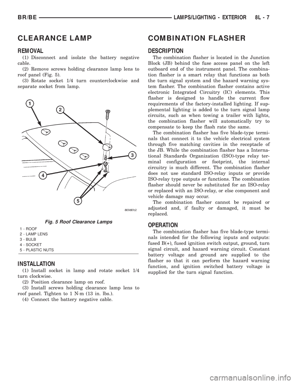
(2) Remove screws holding clearance lamp lens to
roof panel (Fig. 5).
(3) Rotate socket 1/4 turn counterclockwise and
separate socket from lamp.
INSTALLATION
(1) Install socket in lamp and rotate socket 1/4
turn clockwise.
(2) Position clearance lamp on roof.
(3) Install screws holding clearance lamp lens to
roof panel. Tighten to 1 N´m (13 in. lbs.).
(4) Connect the battery negative cable.
COMBINATION FLASHER
DESCRIPTION
The combination flasher is located in the Junction
Block (JB) behind the fuse access panel on the left
outboard end of the instrument panel. The combina-
tion flasher is a smart relay that functions as both
the turn signal system and the hazard warning sys-
tem flasher. The combination flasher contains active
electronic Integrated Circuitry (IC) elements. This
flasher is designed to handle the current flow
requirements of the factory-installed lighting. If sup-
plemental lighting is added to the turn signal lamp
circuits, such as when towing a trailer with lights,
the combination flasher will automatically try to
compensate to keep the flash rate the same.
The combination flasher has five blade-type termi-
nals that connect it to the vehicle electrical system
through five matching cavities in the receptacle of
the JB. While the combination flasher has a Interna-
tional Standards Organization (ISO)-type relay ter-
minal configuration or footprint, the internal
circuitry is much different. The combination flasher
does not use standard ISO-relay inputs or provide
ISO-relay type outputs or functions. The combination
flasher should never be substituted for an ISO-relay
or replaced with an ISO-relay, or else component and
vehicle damage may occur.
The combination flasher cannot be repaired or
adjusted and, if faulty or damaged, it must be
replaced.
OPERATION
The combination flasher has five blade-type termi-
nals intended for the following inputs and outputs:
fused B(+), fused ignition switch output, ground, turn
signal circuit, and hazard warning circuit. Constant
battery voltage and ground are supplied to the
flasher so that it can perform the hazard warning
function, and ignition switched battery voltage is
supplied for the turn signal function.
Fig. 5 Roof Clearance Lamps
1 - ROOF
2 - LAMP LENS
3 - BULB
4 - SOCKET
5 - PLASTIC NUTS
BR/BELAMPS/LIGHTING - EXTERIOR 8L - 7