2002 DODGE RAM Wiring diagram
[x] Cancel search: Wiring diagramPage 675 of 2255
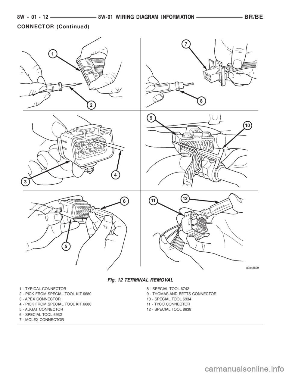
Fig. 12 TERMINAL REMOVAL
1 - TYPICAL CONNECTOR
2 - PICK FROM SPECIAL TOOL KIT 6680
3 - APEX CONNECTOR
4 - PICK FROM SPECIAL TOOL KIT 6680
5 - AUGAT CONNECTOR
6 - SPECIAL TOOL 6932
7 - MOLEX CONNECTOR8 - SPECIAL TOOL 6742
9 - THOMAS AND BETTS CONNECTOR
10 - SPECIAL TOOL 6934
11 - TYCO CONNECTOR
12 - SPECIAL TOOL 8638
8W - 01 - 12 8W-01 WIRING DIAGRAM INFORMATIONBR/BE
CONNECTOR (Continued)
Page 676 of 2255
DIODE
REMOVAL
(1) Disconnect the battery.
(2) Locate the diode in the harness, and remove
the protective covering.
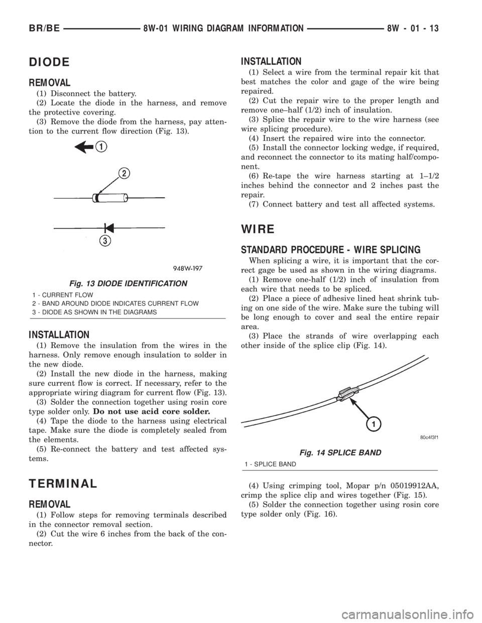
(3) Remove the diode from the harness, pay atten-
tion to the current flow direction (Fig. 13).
INSTALLATION
(1) Remove the insulation from the wires in the
harness. Only remove enough insulation to solder in
the new diode.
(2) Install the new diode in the harness, making
sure current flow is correct. If necessary, refer to the
appropriate wiring diagram for current flow (Fig. 13).
(3) Solder the connection together using rosin core
type solder only.Do not use acid core solder.
(4) Tape the diode to the harness using electrical
tape. Make sure the diode is completely sealed from
the elements.
(5) Re-connect the battery and test affected sys-
tems.
TERMINAL
REMOVAL
(1) Follow steps for removing terminals described
in the connector removal section.
(2) Cut the wire 6 inches from the back of the con-
nector.
INSTALLATION
(1) Select a wire from the terminal repair kit that
best matches the color and gage of the wire being
repaired.
(2) Cut the repair wire to the proper length and
remove one±half (1/2) inch of insulation.
(3) Splice the repair wire to the wire harness (see
wire splicing procedure).
(4) Insert the repaired wire into the connector.
(5) Install the connector locking wedge, if required,
and reconnect the connector to its mating half/compo-
nent.
(6) Re-tape the wire harness starting at 1±1/2
inches behind the connector and 2 inches past the
repair.
(7) Connect battery and test all affected systems.
WIRE
STANDARD PROCEDURE - WIRE SPLICING
When splicing a wire, it is important that the cor-
rect gage be used as shown in the wiring diagrams.
(1) Remove one-half (1/2) inch of insulation from
each wire that needs to be spliced.
(2) Place a piece of adhesive lined heat shrink tub-
ing on one side of the wire. Make sure the tubing will
be long enough to cover and seal the entire repair
area.
(3) Place the strands of wire overlapping each
other inside of the splice clip (Fig. 14).
(4) Using crimping tool, Mopar p/n 05019912AA,
crimp the splice clip and wires together (Fig. 15).
(5) Solder the connection together using rosin core
type solder only (Fig. 16).
Fig. 13 DIODE IDENTIFICATION
1 - CURRENT FLOW
2 - BAND AROUND DIODE INDICATES CURRENT FLOW
3 - DIODE AS SHOWN IN THE DIAGRAMS
Fig. 14 SPLICE BAND
1 - SPLICE BAND
BR/BE8W-01 WIRING DIAGRAM INFORMATION 8W - 01 - 13
Page 677 of 2255
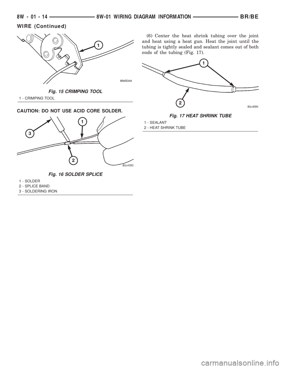
CAUTION: DO NOT USE ACID CORE SOLDER.(6) Center the heat shrink tubing over the joint
and heat using a heat gun. Heat the joint until the
tubing is tightly sealed and sealant comes out of both
ends of the tubing (Fig. 17).
Fig. 15 CRIMPING TOOL
1 - CRIMPING TOOL
Fig. 16 SOLDER SPLICE
1 - SOLDER
2 - SPLICE BAND
3 - SOLDERING IRON
Fig. 17 HEAT SHRINK TUBE
1 - SEALANT
2 - HEAT SHRINK TUBE
8W - 01 - 14 8W-01 WIRING DIAGRAM INFORMATIONBR/BE
WIRE (Continued)
Page 1018 of 2255
8W-91 CONNECTOR/GROUND/SPLICE LOCATION
TABLE OF CONTENTS
page
CONNECTOR/GROUND/SPLICE LOCATION
DESCRIPTION..........................1
CONNECTOR/GROUND/SPLICE
LOCATION
DESCRIPTION
This section provides illustrations identifying con-
nector, ground, and splice locations in the vehicle.Connector, ground, and splice indexes are provided.
Use the wiring diagrams in each section for connec-
tor, ground, and splice identification. Refer to the
index for the proper figure number. For items that
are not shown in this section N/S is placed in the
Fig. column.
CONNECTORS
CONNECTOR NAME/
NUMBERCOLOR LOCATION FIG.
4WD Switch BK On Front Axle N/S
A/C Compressor Clutch BK Rear of A/C Compressor 7, 8, 11
A/C Heater Control BK Center of Instrument Panel 33
A/C Heater Temperature
SelectNAT Center of Instrument Panel 33
A/C High Pressure Switch BK At A/C Compressor 7, 8, 11
A/C Low Pressure Switch BK Top of A/C Accumulator 1, 3
Accelerator Pedal Position
Sensor (Diesel)Left Front of Engine 13, 14
Aftermarket Trailer Tow
ConnectorRear of Vehicle N/S
Airbag Control Module Center of I.P. at Airbag Control Module 30
Ambient Temperature Sensor BK Radiator Left Support N/S
Ash Receiver Lamp BK Center of Instrument Panel 34
Back-up Lamp Switch (M/T) BK Top of Transmission 16
Battery Temperature Sensor BK Below Battery Tray 21
Blend Door Actuator Center of Instrument Panel N/S
Blower Motor BK Bottom Right of Instrument Panel 30
Blower Motor Resistor Block BK Bottom Right of Instrument Panel 34
Brake Lamp Switch Brake Pedal Arm 30, 32
Brake Pressure Switch BK At Master Cylinder 18
Bypass Jumper (A/T) GN Top Of Clutch Pedal 35
C105 Rear of Front Bumper N/S
C106 BK Rear of Front Bumper 22
C114 BK Radiator Left Support 20
C125 (Diesel) BK Left Rear of Engine Compartment 3
BR/BE8W-91 CONNECTOR/GROUND/SPLICE LOCATION 8W - 91 - 1
Page 1061 of 2255
tribution points for the electrical current required to
operate all of the many standard and optional facto-
ry-installed electrical and electronic powertrain,
chassis, safety, security, comfort and convenience sys-
tems. At the same time, the power distribution sys-
tem was designed to provide ready access to these
electrical distribution points for the vehicle techni-
cian to use when conducting diagnosis and repair of
faulty circuits. The power distribution system can
also prove useful for the sourcing of additional elec-
trical circuits that may be required to provide the
electrical current needed to operate many accessories
that the vehicle owner may choose to have installed
in the aftermarket.
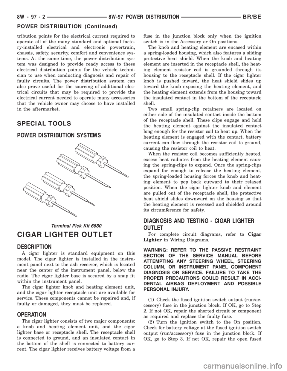
SPECIAL TOOLS
POWER DISTRIBUTION SYSTEMS
CIGAR LIGHTER OUTLET
DESCRIPTION
A cigar lighter is standard equipment on this
model. The cigar lighter is installed in the instru-
ment panel next to the ash receiver, which is located
near the center of the instrument panel, below the
radio. The cigar lighter base is secured by a snap fit
within the instrument panel.
The cigar lighter knob and heating element unit,
and the cigar lighter receptacle unit are available for
service. These components cannot be repaired and, if
faulty or damaged, they must be replaced.
OPERATION
The cigar lighter consists of two major components:
a knob and heating element unit, and the cigar
lighter base or receptacle shell. The receptacle shell
is connected to ground, and an insulated contact in
the bottom of the shell is connected to battery cur-
rent. The cigar lighter receives battery voltage from afuse in the junction block only when the ignition
switch is in the Accessory or On positions.
The knob and heating element are encased within
a spring-loaded housing, which also features a sliding
protective heat shield. When the knob and heating
element are inserted in the receptacle shell, the heat-
ing element resistor coil is grounded through its
housing to the receptacle shell. If the cigar lighter
knob is pushed inward, the heat shield slides up
toward the knob exposing the heating element, and
the heating element extends from the housing toward
the insulated contact in the bottom of the receptacle
shell.
Two small spring-clip retainers are located on
either side of the insulated contact inside the bottom
of the receptacle shell. These clips engage and hold
the heating element against the insulated contact
long enough for the resistor coil to heat up. When the
heating element is engaged with the contact, battery
current can flow through the resistor coil to ground,
causing the resistor coil to heat.
When the resistor coil becomes sufficiently heated,
excess heat radiates from the heating element caus-
ing the spring-clips to expand. Once the spring-clips
expand far enough to release the heating element,
the spring-loaded housing forces the knob and heat-
ing element to pop back outward to their relaxed
position. When the cigar lighter knob and element
are pulled out of the receptacle shell, the protective
heat shield slides downward on the housing so that
the heating element is recessed and shielded around
its circumference for safety.
DIAGNOSIS AND TESTING - CIGAR LIGHTER
OUTLET
For complete circuit diagrams, refer toCigar
Lighterin Wiring Diagrams.
WARNING: REFER TO THE PASSIVE RESTRAINT
SECTION OF THE SERVICE MANUAL BEFORE
ATTEMPTING ANY STEERING WHEEL, STEERING
COLUMN, OR INSTRUMENT PANEL COMPONENT
DIAGNOSIS OR SERVICE. FAILURE TO TAKE THE
PROPER PRECAUTIONS COULD RESULT IN ACCI-
DENTAL AIRBAG DEPLOYMENT AND POSSIBLE
PERSONAL INJURY.
(1) Check the fused ignition switch output (run/ac-
cessory) fuse in the junction block. If OK, go to Step
2. If not OK, repair the shorted circuit or component
as required and replace the faulty fuse.
(2) Turn the ignition switch to the On position.
Check for battery voltage at the fused ignition switch
output (run/accessory) fuse in the junction block. If
OK, go to Step 3. If not OK, repair the open fused
Terminal Pick Kit 6680
8W - 97 - 2 8W-97 POWER DISTRIBUTIONBR/BE
POWER DISTRIBUTION (Continued)
Page 1066 of 2255
tor between many of the engine compartment, instru-
ment panel, and body wire harnesses. The JB houses
up to nineteen blade-type fuses (two standard-type
and seventeen mini-type), up to two blade-type auto-
matic resetting circuit breakers, the electronic combi-
nation turn signal and hazard warning flasher, and
one International Standards Organization (ISO)
micro-relay.
The molded plastic JB housing has integral mount-
ing brackets that are secured with two screws to the
left instrument panel end bracket. The left end of the
instrument panel cover has a snap-fit fuse access
panel that can be removed for service of the JB. A
fuse puller and spare fuse holders are located on the
back of the fuse access cover, as well as an adhesive-
backed fuse layout map to ensure proper fuse identi-
fication.
The JB unit cannot be repaired and is only ser-
viced as an assembly. If any internal circuit or the JB
housing is faulty or damaged, the entire JB unit
must be replaced.
OPERATION
All of the circuits entering and leaving the JB do
so through up to nine wire harness connectors, which
are connected to the JB through integral connector
receptacles molded into the JB housing. Internal con-
nection of all of the JB circuits is accomplished by an
intricate combination of hard wiring and bus bars.
Refer toWiring Diagramsfor the location of com-
plete JB circuit diagrams.
DIAGNOSIS AND TESTING - JUNCTION BLOCK
The junction block does not incorporate any self
diagnostic capability. Most of the electrical circuits
incorporated into the vehicle must pass through the
junction block at one point or another. The most effi-
cient means of diagnosing a suspected junction block
problem involves a simple continuity tester or ohm
meter. Using the Wiring Diagrams as a guide trace
the problem circuit to the proper junction block cav-
ity and test all circuits in the effected circuit for
proper continuity. A open or high resistance circuit is
a sign of a problem. Some other possible junction
block problems to look for are:
²Loose fuse receptacle terminals.
²Loose relay / circuit breaker receptacle termi-
nals.
²Bent or distorted electrical circuit pins.
²Incorrect size fuse installed in junction block
fuse cavity.
²Dark areas identifying a source of excess heat.
²Defective fuse, relay or circuit breaker installed
in junction block cavity.
REMOVAL
(1) Disconnect and isolate the battery negative
cable.
(2) Remove the fuse access bezel from the instru-
ment panel.
(3) Remove the steering column cover (Refer to 23
- BODY/INSTRUMENT PANEL/STEERING COL-
UMN OPENING COVER - REMOVAL).
(4) Remove the hood release handle retaining
screws and position the handle assembly out of the
way.
(5) Remove the lower knee blocker from the instru-
ment panel.
(6) Pull drivers side carpet down, out of the way.
(7) Remove the parking brake switch connector,
release linkage and retaining fasteners and position
the assembly out the drivers door opening.
(8) Remove the electrical ground connections,
located behind park brake mounting location.
(9) Remove the two junction block retaining
screws. To access the upper retaining screw a 15 inch
long #2 Phillips screwdriver will be required. Access
the upper screw through hole in dash support brace.
(10) Reach through the outboard side of the instru-
ment panel steering column opening to access and
disconnect all of the wire harness connectors from
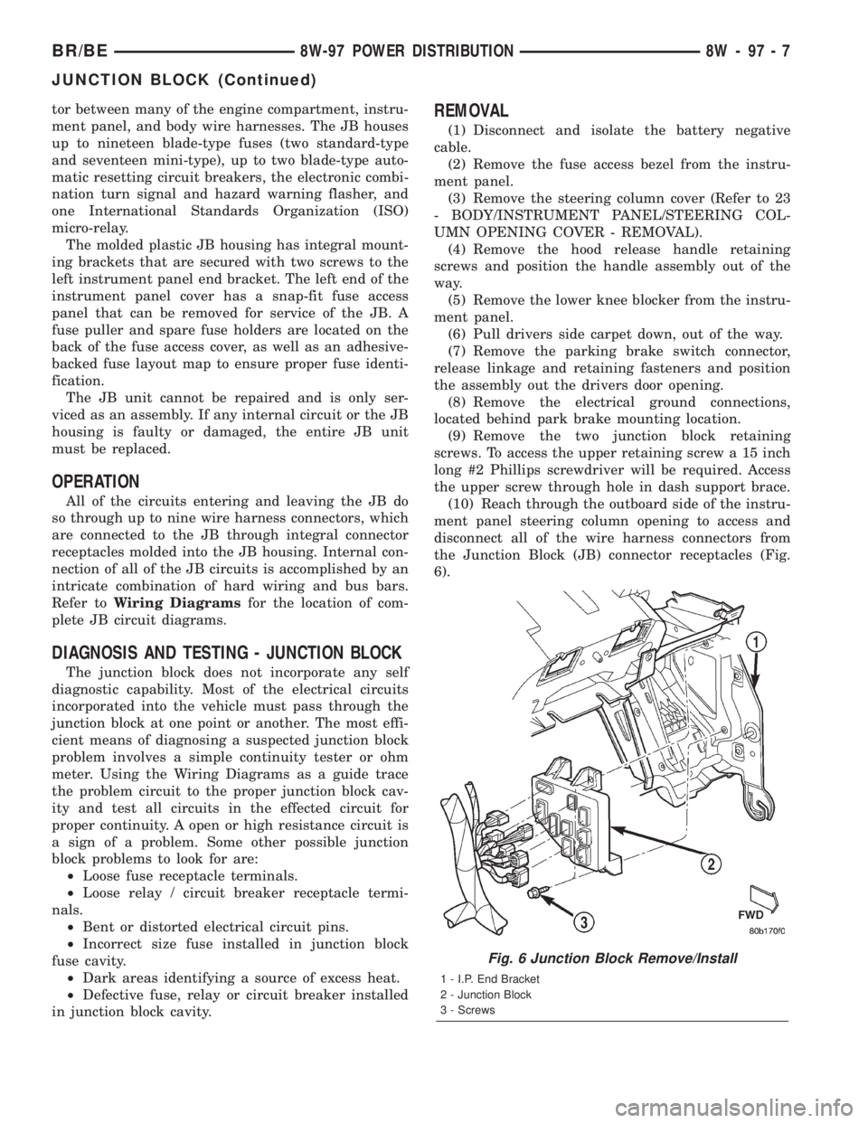
the Junction Block (JB) connector receptacles (Fig.
6).
Fig. 6 Junction Block Remove/Install
1 - I.P. End Bracket
2 - Junction Block
3 - Screws
BR/BE8W-97 POWER DISTRIBUTION 8W - 97 - 7
JUNCTION BLOCK (Continued)
Page 1067 of 2255
(11) Remove the junction block from under the
instrument panel.
INSTALLATION
NOTE: If the Junction Block (JB) is being replaced
with a new unit, be certain to transfer each of the
fuses, circuit breakers and relays from the faulty JB
to the proper cavities of the replacement JB. Refer
to Junction Block in the index of this service man-
ual for the location of complete circuit diagrams
and cavity assignments for the JB.
(1) Position the junction block under the instru-
ment panel.
(2) Connect all of the wire harness connectors on
the Junction Block (JB) connector receptacles.
(3) Install the two junction block retaining screws.
(4) Install the electrical ground connections,
located behind park brake mounting location.
(5) Install the parking brake switch connector,
release linkage and retaining fasteners.
(6) Reposition drivers side carpet.
(7) Install the lower knee blocker on the instru-
ment panel.
(8) Install the hood release handle retaining
screws.
(9) Install the steering column cover.
(10) Install the fuse access bezel on the instrument
panel.
(11) Connect the battery negative cable.
POWER DISTRIBUTION
CENTER
DESCRIPTION
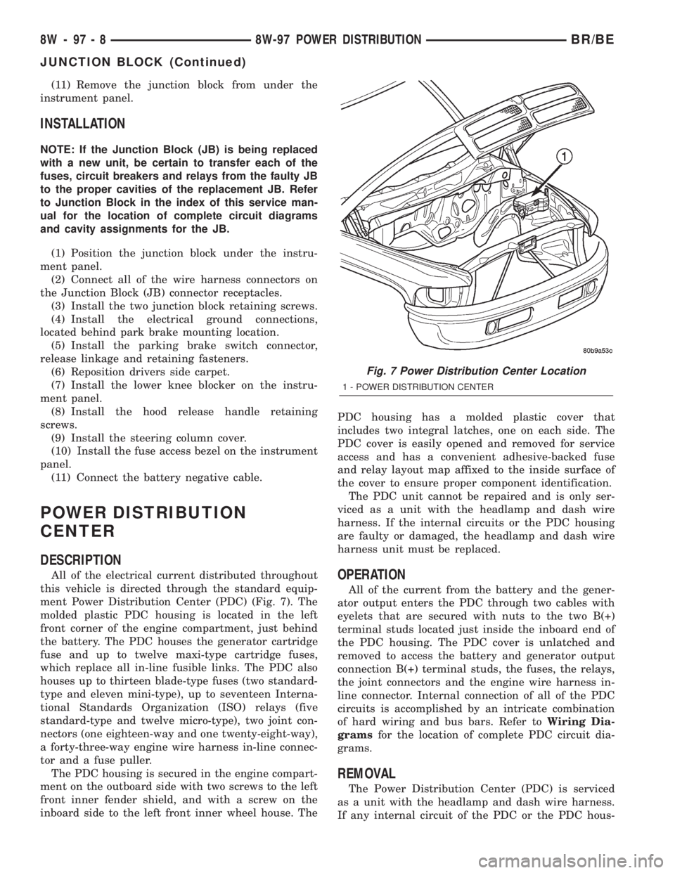
All of the electrical current distributed throughout
this vehicle is directed through the standard equip-
ment Power Distribution Center (PDC) (Fig. 7). The
molded plastic PDC housing is located in the left
front corner of the engine compartment, just behind
the battery. The PDC houses the generator cartridge
fuse and up to twelve maxi-type cartridge fuses,
which replace all in-line fusible links. The PDC also
houses up to thirteen blade-type fuses (two standard-
type and eleven mini-type), up to seventeen Interna-
tional Standards Organization (ISO) relays (five
standard-type and twelve micro-type), two joint con-
nectors (one eighteen-way and one twenty-eight-way),
a forty-three-way engine wire harness in-line connec-
tor and a fuse puller.
The PDC housing is secured in the engine compart-
ment on the outboard side with two screws to the left
front inner fender shield, and with a screw on the
inboard side to the left front inner wheel house. ThePDC housing has a molded plastic cover that
includes two integral latches, one on each side. The
PDC cover is easily opened and removed for service
access and has a convenient adhesive-backed fuse
and relay layout map affixed to the inside surface of
the cover to ensure proper component identification.
The PDC unit cannot be repaired and is only ser-
viced as a unit with the headlamp and dash wire
harness. If the internal circuits or the PDC housing
are faulty or damaged, the headlamp and dash wire
harness unit must be replaced.OPERATION
All of the current from the battery and the gener-
ator output enters the PDC through two cables with
eyelets that are secured with nuts to the two B(+)
terminal studs located just inside the inboard end of
the PDC housing. The PDC cover is unlatched and
removed to access the battery and generator output
connection B(+) terminal studs, the fuses, the relays,
the joint connectors and the engine wire harness in-
line connector. Internal connection of all of the PDC
circuits is accomplished by an intricate combination
of hard wiring and bus bars. Refer toWiring Dia-
gramsfor the location of complete PDC circuit dia-
grams.
REMOVAL
The Power Distribution Center (PDC) is serviced
as a unit with the headlamp and dash wire harness.
If any internal circuit of the PDC or the PDC hous-
Fig. 7 Power Distribution Center Location
1 - POWER DISTRIBUTION CENTER
8W - 97 - 8 8W-97 POWER DISTRIBUTIONBR/BE
JUNCTION BLOCK (Continued)
Page 1069 of 2255
INSTALLATION
The Power Distribution Center (PDC) is serviced
as a unit with the headlamp and dash wire harness.
If any internal circuit of the PDC or the PDC hous-
ing is faulty or damaged, the entire PDC and head-
lamp and dash wire harness unit must be replaced.
NOTE: If the PDC is being replaced with a new unit,
be certain to transfer each of the blade-type fuses,
cartridge fuses and relays from the faulty PDC to
the proper cavities of the replacement PDC. Refer
to Power Distribution in the index of this service
manual for the location of complete PDC circuit dia-
grams and cavity assignments.
(1) Position the PDC and the headlamp and dash
wire harness unit in the engine compartment.
(2) Install and tighten the two screws that secure
the PDC housing to the left front fender inner shield.
Tighten the screws to 8.4 N´m (75 in. lbs.).
(3) Install and tighten the screw that secures the
PDC housing to the left front fender wheel housing.
Tighten the screw to 2.2 N´m (20 in. lbs.).
(4) Install the eyelet of the battery positive cable
PDC take out onto the forward B(+) terminal stud in
the PDC.
(5) Install and tighten the nut that secures the
eyelet of the battery positive cable PDC take out to
the forward B(+) terminal stud in the PDC. Tighten
the nut to 8.4 N´m (75 in. lbs.).
(6) Install the eyelet of the battery negative cable
generator output take out onto the rearward B(+) ter-
minal stud in the PDC.
(7) Install and tighten the nut that secures the
eyelet of the battery negative cable generator output
take out to the rearward B(+) terminal stud in the
PDC. Tighten the nut to 75 in. lbs.
(8) Reconnect the engine wire harness in-line con-
nector to the PDC.
(9) Install and tighten the screw that secures the
engine wire harness in-line connector to the PDC.
Tighten the screw until a distinct audible click is
heard.
(10) Install and latch the cover onto the PDC.
(11) Engage each of the retainers that secure the
headlamp and dash wire harness to the vehicle body
and chassis components. Refer toConnector Loca-
tionsin Wiring for the location of more information
on the headlamp and dash wire harness retainer
locations.
(12) Install all of the fasteners that secure each of
the headlamp and dash wire harness ground eyelets
to the vehicle body and chassis components. Refer to
Connector Locationsin Wiring for the location of
more information on the ground eyelet locations.(13) Reconnect each of the headlamp and dash
wire harness connectors. Refer toConnector Loca-
tionsin Wiring for the location of more information
on the headlamp and dash wire harness connector
locations.
(14) Reconnect the battery negative cable.
POWER OUTLET
DESCRIPTION
Two power outlets are installed in the vehicle. One
in the instrument panel next to the cigar lighter and
the other in the right rear quarter trim panel. The
power outlet bases are secured by a snap fit within
the instrument panel or trim panel. A plastic protec-
tive cap snaps into the power outlet base when the
power outlet is not being used, and hangs from the
power outlet base mount by an integral bail strap
while the power outlet is in use.
The power outlet receptacle unit and the accessory
power outlet protective cap are available for service.
The power outlet receptacle cannot be repaired and,
if faulty or damaged, it must be replaced.
OPERATION
The power outlet base or receptacle shell is con-
nected to ground, and an insulated contact in the
bottom of the shell is connected to battery current.
The power outlet receives battery voltage from a fuse
in the Junction Block at all times.
While the power outlet is very similar to a cigar
lighter base unit, it does not include the two small
spring-clip retainers inside the bottom of the recepta-
cle shell that are used to secure the cigar lighter
heating element to the insulated contact.
DIAGNOSIS AND TESTING - POWER OUTLET
For complete circuit diagrams, refer toPower
Outletin Wiring Diagrams.
(1) Check the fused B(+) fuse in the junction block.
If OK, go to Step 2. If not OK, repair the shorted cir-
cuit or component as required and replace the faulty
fuse.
(2) Check for battery voltage at the fused B(+) fuse
in the junction block. If OK, go to Step 3. If not OK,
repair the open fused B(+) circuit to the battery as
required.
(3) Remove the plastic protective cap from the
power outlet receptacle. Check for continuity between
the inside circumference of the power outlet recepta-
cle and a good ground. There should be continuity. If
OK, go to Step 4. If not OK, go to Step 5.
(4) Check for battery voltage at the insulated con-
tact located at the back of the power outlet recepta-
cle. If not OK, go to Step 5.
8W - 97 - 10 8W-97 POWER DISTRIBUTIONBR/BE
POWER DISTRIBUTION CENTER (Continued)