2002 DODGE RAM Wiring diagram
[x] Cancel search: Wiring diagramPage 2138 of 2255
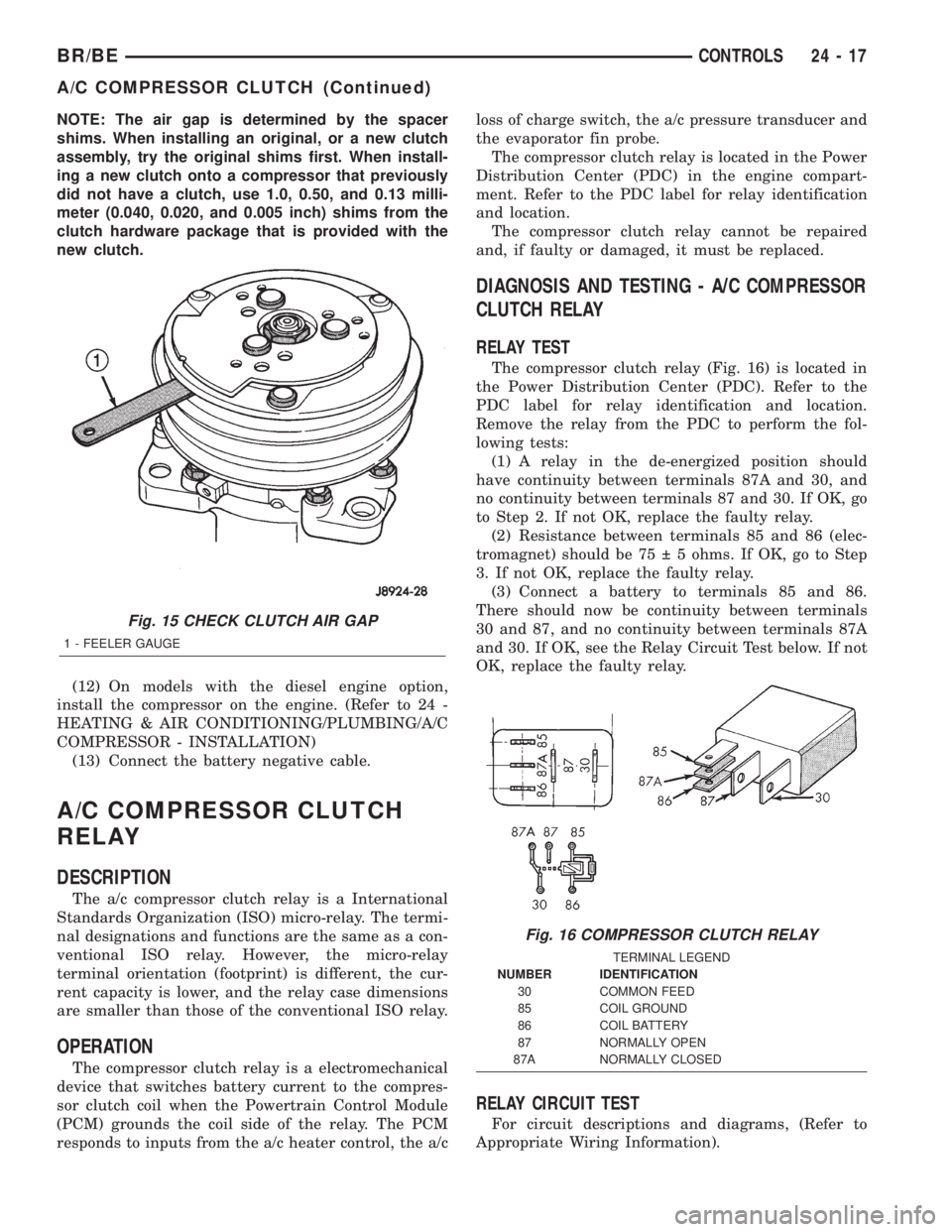
NOTE: The air gap is determined by the spacer
shims. When installing an original, or a new clutch
assembly, try the original shims first. When install-
ing a new clutch onto a compressor that previously
did not have a clutch, use 1.0, 0.50, and 0.13 milli-
meter (0.040, 0.020, and 0.005 inch) shims from the
clutch hardware package that is provided with the
new clutch.
(12) On models with the diesel engine option,
install the compressor on the engine. (Refer to 24 -
HEATING & AIR CONDITIONING/PLUMBING/A/C
COMPRESSOR - INSTALLATION)
(13) Connect the battery negative cable.
A/C COMPRESSOR CLUTCH
RELAY
DESCRIPTION
The a/c compressor clutch relay is a International
Standards Organization (ISO) micro-relay. The termi-
nal designations and functions are the same as a con-
ventional ISO relay. However, the micro-relay
terminal orientation (footprint) is different, the cur-
rent capacity is lower, and the relay case dimensions
are smaller than those of the conventional ISO relay.
OPERATION
The compressor clutch relay is a electromechanical
device that switches battery current to the compres-
sor clutch coil when the Powertrain Control Module
(PCM) grounds the coil side of the relay. The PCM
responds to inputs from the a/c heater control, the a/closs of charge switch, the a/c pressure transducer and
the evaporator fin probe.
The compressor clutch relay is located in the Power
Distribution Center (PDC) in the engine compart-
ment. Refer to the PDC label for relay identification
and location.
The compressor clutch relay cannot be repaired
and, if faulty or damaged, it must be replaced.
DIAGNOSIS AND TESTING - A/C COMPRESSOR
CLUTCH RELAY
RELAY TEST
The compressor clutch relay (Fig. 16) is located in
the Power Distribution Center (PDC). Refer to the
PDC label for relay identification and location.
Remove the relay from the PDC to perform the fol-
lowing tests:
(1) A relay in the de-energized position should
have continuity between terminals 87A and 30, and
no continuity between terminals 87 and 30. If OK, go
to Step 2. If not OK, replace the faulty relay.
(2) Resistance between terminals 85 and 86 (elec-
tromagnet) should be 75 5 ohms. If OK, go to Step
3. If not OK, replace the faulty relay.
(3) Connect a battery to terminals 85 and 86.
There should now be continuity between terminals
30 and 87, and no continuity between terminals 87A
and 30. If OK, see the Relay Circuit Test below. If not
OK, replace the faulty relay.
RELAY CIRCUIT TEST
For circuit descriptions and diagrams, (Refer to
Appropriate Wiring Information).
Fig. 15 CHECK CLUTCH AIR GAP
1 - FEELER GAUGE
Fig. 16 COMPRESSOR CLUTCH RELAY
TERMINAL LEGEND
NUMBER IDENTIFICATION
30 COMMON FEED
85 COIL GROUND
86 COIL BATTERY
87 NORMALLY OPEN
87A NORMALLY CLOSED
BR/BECONTROLS 24 - 17
A/C COMPRESSOR CLUTCH (Continued)
Page 2141 of 2255
(4) Reinstall the cluster bezel to the instrument
panel(Refer to 23 - BODY/INSTRUMENT PANEL/
CLUSTER BEZEL - INSTALLATION).
(5) Reach under the instrument panel to reinstall
the a/c heater control vacuum harness retainer to the
side of the center distribution duct.
(6) Plug in the two halves of the a/c heater control
to HVAC housing vacuum harness connector.
(7) Connect the battery negative cable.
A/C HIGH PRESSURE SWITCH
DESCRIPTION
The a/c high pressure switch is located on the dis-
charge line near the compressor. The switch is
screwed onto a fitting that contains a Schrader-type
valve, which allows the switch to be serviced without
discharging the refrigerant system. The discharge
line fitting is equipped with an O-ring to seal the
switch connection.
OPERATION
The a/c high pressure switch is connected in series
electrically with the a/c low pressure switch between
ground and the Powertrain Control Module (PCM).
The switch contacts open and close causing the PCM
to turn the compressor clutch on and off. This pre-
vents compressor operation when the discharge line
pressure approaches high levels.
The a/c high pressure switch contacts are open
when the discharge line pressure rises above about3100 to 3375 kPa (450 to 490 psi). The switch con-
tacts will close when the discharge line pressure
drops to about 1860 to 2275 kPa (270 to 330 psi).
When checking refrigerant system pressures with a
manifold gauge set, keep in mind that the indicated
pressures will be about 172 kpa (25 psi) below the
actual switch pressure values due to the pressure
drop that occurs in the refrigerant system between
the switch and the high pressure service port.
The a/c high pressure switch is a factory-calibrated
unit. The switch cannot be adjusted or repaired and,
if faulty or damaged, it must be replaced.
DIAGNOSIS AND TESTING - A/C HIGH
PRESSURE SWITCH
Before performing diagnosis of the a/c high pres-
sure switch, verify that the refrigerant system has
the correct refrigerant charge. (Refer to 24 - HEAT-
ING & AIR CONDITIONING - DIAGNOSIS AND
TESTING)
For circuit descriptions and diagrams, (Refer to
Appropriate Wiring Information).
(1) Disconnect and isolate the battery negative
cable.
(2) Unplug the a/c high pressure switch wire har-
ness connector from the switch on the refrigerant
system fitting.
(3) On the four terminal high pressure switch,
check for continuity between terminals C and D. On
the two terminal switch, check for continuity
between both terminals of the a/c high pressure
switch. There should be continuity. If OK, test and
repair the A/C switch sense circuit as required. If not
OK, replace the faulty switch.
REMOVAL
(1) Disconnect and isolate the battery negative
cable.
(2) Unplug the wire harness connector from the a/c
high pressure switch, which is mounted to a fitting
on the discharge line between the compressor and
the condenser inlet.
(3) Unscrew the a/c high pressure switch from the
discharge line fitting.
(4) Remove the a/c high pressure switch from the
vehicle.
(5) Remove the O-ring seal from the discharge line
fitting and discard.
INSTALLATION
(1) Lubricate a new O-ring seal with clean refrig-
erant oil and install it on the discharge line fitting.
Use only the specified O-rings as they are made of a
special material for the R-134a system. Use only
refrigerant oil of the type recommended for the com-
pressor in the vehicle. (Refer to 24 - HEATING &
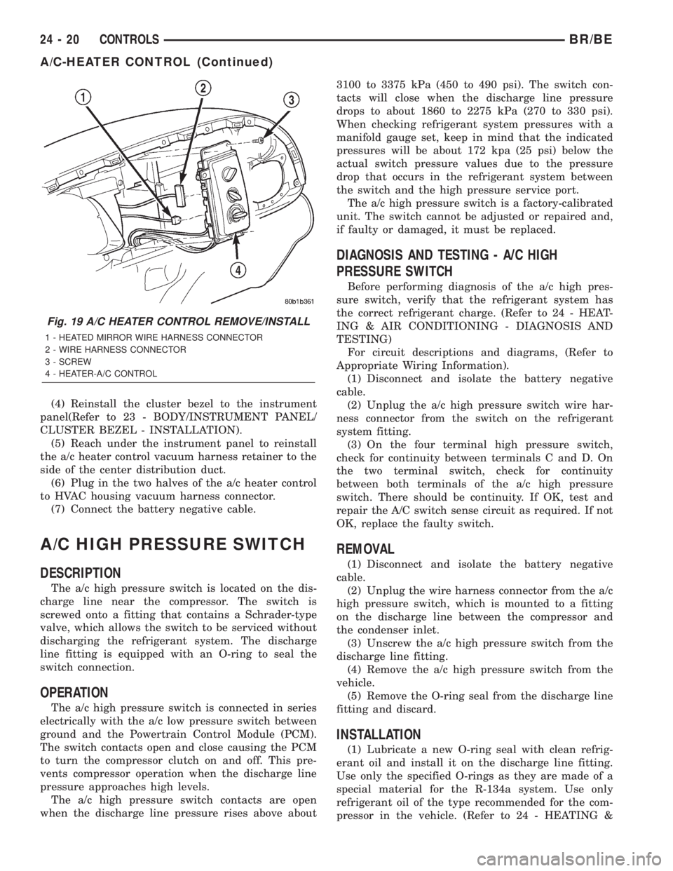
Fig. 19 A/C HEATER CONTROL REMOVE/INSTALL
1 - HEATED MIRROR WIRE HARNESS CONNECTOR
2 - WIRE HARNESS CONNECTOR
3 - SCREW
4 - HEATER-A/C CONTROL
24 - 20 CONTROLSBR/BE
A/C-HEATER CONTROL (Continued)
Page 2142 of 2255
AIR CONDITIONING/PLUMBING/REFRIGERANT
OIL - DESCRIPTION)
(2) Install and tighten the high pressure cut-off
switch on the discharge line fitting. The switch
should be hand-tightened onto the discharge line fit-
ting.
(3) Plug the wire harness connector into the high
pressure cut-off switch.
(4) Connect the battery negative cable.
A/C LOW PRESSURE SWITCH
DESCRIPTION
The a/c low pressure switch is located on the top of
the accumulator. The switch is screwed onto an accu-
mulator fitting that contains a Schrader-type valve,
which allows the switch to be serviced without dis-
charging the refrigerant system. The accumulator fit-
ting is equipped with an O-ring to seal the switch
connection.
OPERATION
The a/c low pressure switch is connected in series
electrically with the a/c high pressure switch and the
a/c heater control, between ground and the Power-
train Control Module (PCM). The switch contacts
open and close causing the PCM to turn the compres-
sor clutch on and off. This regulates the refrigerant
system pressure and controls evaporator tempera-
ture. Controlling evaporator temperature prevents
condensate water on the evaporator fins from freez-
ing and obstructing air conditioning system air flow.
The a/c low pressure switch contacts are open
when the suction pressure is about 152-165 kPa
(22-24 psi) or lower. The switch contacts will close
when the suction pressure rises to about 255-296 kPa
(37-43 psi) or above. Lower ambient temperatures,
below about -1É C (30É F), will also cause the switch
contacts to open. This is due to the pressure/temper-
ature relationship of the refrigerant in the system.
The a/c low pressure switch is a factory-calibrated
unit. It cannot be adjusted or repaired and, if faulty
or damaged, it must be replaced.
DIAGNOSIS AND TESTING - A/C LOW
PRESSURE SWITCH
Before performing diagnosis of the a/c low pressure
switch, be certain that the switch is properly
installed on the accumulator fitting. If the switch is
too loose it may not open the Schrader-type valve in
the accumulator fitting, which will prevent the
switch from correctly monitoring the refrigerant sys-
tem pressure. Also verify that the refrigerant system
has the correct refrigerant charge. (Refer to 24 -HEATING & AIR CONDITIONING - DIAGNOSIS
AND TESTING - A/C PERFORMANCE)
Remember that lower ambient temperatures, below
about -1É C (30É F), during cold weather will open the
switch contacts and prevent compressor operation
due to the pressure/temperature relationship of the
refrigerant. For circuit descriptions and diagrams,
(Refer to Appropriate Wiring Information).
(1) Disconnect and isolate the battery negative
cable.
(2) Unplug the a/c low pressure switch wire har-
ness connector from the switch on the accumulator
fitting.
(3) Install a jumper wire between the two cavities
of the a/c low pressure switch wire harness connector.
(4) Connect a manifold gauge set to the refrigerant
system service ports. (Refer to 24 - HEATING & AIR
CONDITIONING/PLUMBING - STANDARD PRO-
CEDURE - REFRIGERANT SYSTEM SERVICE
EQUIPMENT)
(5) Connect the battery negative cable.
(6) Place the a/c heater mode control switch knob
in any A/C position and start the engine.
(7) Check for continuity between the two terminals
of the low pressure cycling clutch switch. There
should be continuity with a suction pressure reading
of 296 kPa (43 psi) or above, and no continuity with a
suction pressure reading of 172 kPa (25 psi) or below.
If OK, test and repair the A/C switch sense circuit as
required. If not OK, replace the faulty switch.
REMOVAL
(1) Disconnect and isolate the battery negative
cable.
(2) Unplug the wire harness connector from the a/c
low pressure switch on the top of the accumulator
(Fig. 20).
(3) Unscrew the a/c low pressure switch from the
fitting on the top of the accumulator.
(4) Remove the O-ring seal from the accumulator
fitting and discard.
INSTALLATION
(1) Lubricate a new O-ring seal with clean refrig-
erant oil and install it on the accumulator fitting.
Use only the specified O-rings as they are made of a
special material for the R-134a system. Use only
refrigerant oil of the type recommended for the com-
pressor in the vehicle. (Refer to 24 - HEATING &
AIR CONDITIONING/PLUMBING/REFRIGERANT
OIL - DESCRIPTION)
(2) Install and tighten the a/c low pressure switch
on the accumulator fitting. The switch should be
hand-tightened onto the accumulator fitting.
(3) Plug the wire harness connector into the a/c
low pressure switch.
BR/BECONTROLS 24 - 21
A/C HIGH PRESSURE SWITCH (Continued)
Page 2143 of 2255
(4) Connect the battery negative cable.
BLOWER MOTOR RELAY
DESCRIPTION
The blower motor relay is an International Stan-
dards Organization (ISO)-type relay. The relay is an
electromechanical device that switches battery cur-
rent from a fuse in the Power Distribution Center
(PDC) directly to the blower motor. The relay is ener-
gized when the relay coil is provided a voltage signal
by the ignition switch. This arrangement reduces the
amount of battery current that must flow through
the ignition switch.
OPERATION
The blower motor relay control circuit is protected
by a fuse located in the junction block. When the
relay is de-energized, the blower motor receives no
battery current.The blower motor relay is located in the PDC in
the engine compartment. Refer to the PDC label for
blower motor relay identification and location.
The blower motor relay cannot be repaired and, if
faulty or damaged, it must be replaced.
DIAGNOSIS AND TESTING - BLOWER MOTOR
RELAY
RELAY TEST
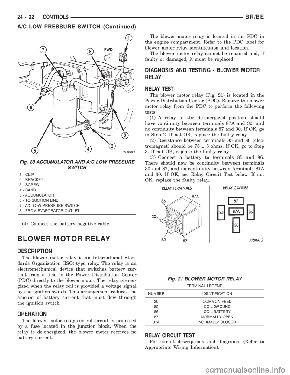
The blower motor relay (Fig. 21) is located in the
Power Distribution Center (PDC). Remove the blower
motor relay from the PDC to perform the following
tests:
(1) A relay in the de-energized position should
have continuity between terminals 87A and 30, and
no continuity between terminals 87 and 30. If OK, go
to Step 2. If not OK, replace the faulty relay.
(2) Resistance between terminals 85 and 86 (elec-
tromagnet) should be 75 5 ohms. If OK, go to Step
3. If not OK, replace the faulty relay.
(3) Connect a battery to terminals 85 and 86.
There should now be continuity between terminals
30 and 87, and no continuity between terminals 87A
and 30. If OK, see Relay Circuit Test below. If not
OK, replace the faulty relay.
RELAY CIRCUIT TEST
For circuit descriptions and diagrams, (Refer to
Appropriate Wiring Information).
Fig. 20 ACCUMULATOR AND A/C LOW PRESSURE
SWITCH
1 - CLIP
2 - BRACKET
3 - SCREW
4 - BAND
5 - ACCUMULATOR
6 - TO SUCTION LINE
7 - A/C LOW PRESSURE SWITCH
8 - FROM EVAPORATOR OUTLET
Fig. 21 BLOWER MOTOR RELAY
TERMINAL LEGEND
NUMBER IDENTIFICATION
30 COMMON FEED
85 COIL GROUND
86 COIL BATTERY
87 NORMALLY OPEN
87A NORMALLY CLOSED
24 - 22 CONTROLSBR/BE
A/C LOW PRESSURE SWITCH (Continued)
Page 2144 of 2255
(1) The relay common feed terminal cavity (30) is
connected to fused battery feed directly from a fuse
in the Power Distribution Center (PDC), and should
be hot at all times. Check for battery voltage at the
PDC cavity for relay terminal 30. If OK, go to Step 2.
If not OK, repair the open circuit to the PDC fuse as
required.
(2) The relay normally closed terminal cavity (87A)
is not used for this application. Go to Step 3.
(3) The relay normally open terminal cavity (87) is
connected to the blower motor. When the relay is
energized, terminal 87 is connected to terminal 30
and provides full battery current to the blower motor
feed circuit. There should be continuity between the
PDC cavity for terminal 87 and the blower motor
relay output circuit cavity of the blower motor wire
harness connector at all times. If OK, go to Step 4. If
not OK, repair the open circuit to the blower motor
as required.
(4) The coil battery terminal cavity (86) is con-
nected to the ignition switch. When the ignition
switch is placed in the On position, fused ignition
switch output is directed from a fuse in the junction
block to the relay electromagnetic coil to energize the
relay. There should be battery voltage at the PDC
cavity for relay terminal 86 with the ignition switch
in the On position. If OK, go to Step 5. If not OK,
repair the open circuit to the junction block fuse as
required.
(5) The coil ground terminal cavity (85) is con-
nected to ground. This terminal supplies the ground
for the relay electromagnetic coil. There should be
continuity between the PDC cavity for relay terminal
85 and a good ground at all times. If not OK, repair
the open circuit as required.
REMOVAL
(1) Disconnect and isolate the battery negative
cable.
(2) Remove the cover from the Power Distribution
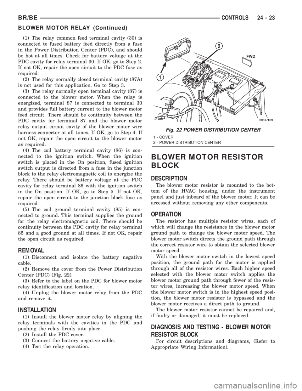
Center (PDC) (Fig. 22).
(3) Refer to the label on the PDC for blower motor
relay identification and location.
(4) Unplug the blower motor relay from the PDC
and remove it.
INSTALLATION
(1) Install the blower motor relay by aligning the
relay terminals with the cavities in the PDC and
pushing the relay firmly into place.
(2) Install the PDC cover.
(3) Connect the battery negative cable.
(4) Test the relay operation.
BLOWER MOTOR RESISTOR
BLOCK
DESCRIPTION
The blower motor resistor is mounted to the bot-
tom of the HVAC housing, under the instrument
panel and just inboard of the blower motor. It can be
accessed without removing any other components.
OPERATION
The resistor has multiple resistor wires, each of
which will change the resistance in the blower motor
ground path to change the blower motor speed. The
blower motor switch directs the ground path through
the correct resistor wire to obtain the selected blower
motor speed.
With the blower motor switch in the lowest speed
position, the ground path for the motor is applied
through all of the resistor wires. Each higher speed
selected with the blower motor switch applies the
blower motor ground path through fewer of the resis-
tor wires, increasing the blower motor speed. When
the blower motor switch is in the highest speed posi-
tion, the blower motor resistor is bypassed and the
blower motor receives a direct path to ground.
The blower motor resistor cannot be repaired and,
if faulty or damaged, it must be replaced.
DIAGNOSIS AND TESTING - BLOWER MOTOR
RESISTOR BLOCK
For circuit descriptions and diagrams, (Refer to
Appropriate Wiring Information).
Fig. 22 POWER DISTRIBUTION CENTER
1 - COVER
2 - POWER DISTRIBUTION CENTER
BR/BECONTROLS 24 - 23
BLOWER MOTOR RELAY (Continued)
Page 2146 of 2255
DIAGNOSIS AND TESTING - BLOWER MOTOR
SWITCH
For circuit descriptions and diagrams, (Refer to
Appropriate Wiring Information).
WARNING: ON VEHICLES EQUIPPED WITH AIR-
BAGS, DISABLE THE AIRBAG SYSTEM BEFORE
ATTEMPTING ANY STEERING WHEEL, STEERING
COLUMN, OR INSTRUMENT PANEL COMPONENT
DIAGNOSIS OR SERVICE. DISCONNECT AND ISO-
LATE THE BATTERY NEGATIVE (GROUND) CABLE,
THEN WAIT TWO MINUTES FOR THE AIRBAG SYS-
TEM CAPACITOR TO DISCHARGE BEFORE PER-
FORMING FURTHER DIAGNOSIS OR SERVICE. THIS
IS THE ONLY SURE WAY TO DISABLE THE AIRBAG
SYSTEM. FAILURE TO TAKE THE PROPER PRE-
CAUTIONS COULD RESULT IN AN ACCIDENTAL
AIRBAG DEPLOYMENT AND POSSIBLE PERSONAL
INJURY.
(1) Check for battery voltage at the fuse in the
Power Distribution Center (PDC). If OK, go to Step
2. If not OK, repair the shorted circuit or component
as required and replace the faulty fuse.
(2) Turn the ignition switch to the Off position.
Disconnect and isolate the battery negative cable.
Remove the a/c heater control from the instrument
panel. (Refer to 24 - HEATING & AIR CONDITION-
ING/CONTROLS/A/C HEATER CONTROL -
REMOVAL) Check for continuity between the ground
circuit cavity of the a/c heater control wire harness
connector and a good ground. There should be conti-
nuity. If OK, go to Step 3. If not OK, repair the open
circuit to ground as required.
(3) With the a/c heater control wire harness con-
nector unplugged, place the a/c heater mode control
switch knob in any position except the Off position.
Check for continuity between the ground circuit ter-
minal and each of the blower motor driver circuit ter-
minals of the a/c heater control as you move the
blower motor switch knob to each of the four speed
positions. There should be continuity at each driver
circuit terminal in only one blower motor switch
speed position. If OK, test and repair the blower
driver circuits between the a/c heater control connec-
tor and the blower motor resistor as required. If not
OK, replace the faulty a/c heater control unit.
REMOVAL
The blower motor switch cannot be repaired and, if
faulty or damaged, the entire heater-only or a/c
heater control unit must be replaced. (Refer to 24 -
HEATING & AIR CONDITIONING/CONTROLS/A/C
HEATER CONTROL - REMOVAL) The blower motor
switch knob is serviced separately.
BLEND DOOR ACTUATOR
REMOVAL
WARNING: ON VEHICLES EQUIPPED WITH AIR-
BAGS, DISABLE THE AIRBAG SYSTEM BEFORE
ATTEMPTING ANY STEERING WHEEL, STEERING
COLUMN, OR INSTRUMENT PANEL COMPONENT
DIAGNOSIS OR SERVICE. DISCONNECT AND ISO-
LATE THE BATTERY NEGATIVE (GROUND) CABLE,
THEN WAIT TWO MINUTES FOR THE AIRBAG SYS-
TEM CAPACITOR TO DISCHARGE BEFORE PER-
FORMING FURTHER DIAGNOSIS OR SERVICE. THIS
IS THE ONLY SURE WAY TO DISABLE THE AIRBAG
SYSTEM. FAILURE TO TAKE THE PROPER PRE-
CAUTIONS COULD RESULT IN AN ACCIDENTAL
AIRBAG DEPLOYMENT AND POSSIBLE PERSONAL
INJURY.
(1) Turn the ignition switch to the run position.
(2) Locate the temperature control knob in the mid
(12 o'clock) position.
(3) Turn the ignition switch to the off position.
(4) Disconnect and isolate the battery negative
cable.
(5) Remove the instrument panel from the vehi-
cle(Refer to 23 - BODY/INSTRUMENT PANEL/IN-
STRUMENT PANEL ASSEMBLY - REMOVAL).
(6) Remove the HVAC housing from the vehicle.
(Refer to 24 - HEATING & AIR CONDITIONING/
DISTRIBUTION/HVAC HOUSING - REMOVAL)
(7) Unplug the wire harness connector from the
blend door actuator (Fig. 24).
(8) Remove the two mounting screws which secure
the actuator to the housing.
(9) Slide the blend door actuator off the blend door
shaft.
NOTE: A black plastic coupler may be attached to
the blend door shaft. Remove the coupler and
inspect for damage. Reinstall if there is no damage
found.
INSTALLATION
NOTE: Before installing the blend door actuator, be
certain that the blend door is not binding and is
capable of full travel in both directions.
(1) Align the actuator with the blend door shaft
and rotate the actuator to align it to the mounting
bosses on the HVAC housing.
(2) Align and install the actuator screws. Tighten
the mounting screws to 2.2 N´m (20 in. lbs.).
(3) Plug in the wire harness connector to the blend
door actuator.
BR/BECONTROLS 24 - 25
BLOWER MOTOR SWITCH (Continued)
Page 2153 of 2255
DIAGNOSIS AND TESTING - BLOWER MOTOR
WARNING: ON VEHICLES EQUIPPED WITH AIR-
BAGS, DISABLE THE AIRBAG SYSTEM BEFORE
ATTEMPTING ANY STEERING WHEEL, STEERING
COLUMN, OR INSTRUMENT PANEL COMPONENT
DIAGNOSIS OR SERVICE. DISCONNECT AND ISO-
LATE THE BATTERY NEGATIVE (GROUND) CABLE,
THEN WAIT TWO MINUTES FOR THE AIRBAG SYS-
TEM CAPACITOR TO DISCHARGE BEFORE PER-
FORMING FURTHER DIAGNOSIS OR SERVICE. THIS
IS THE ONLY SURE WAY TO DISABLE THE AIRBAG
SYSTEM. FAILURE TO TAKE THE PROPER PRE-
CAUTIONS COULD RESULT IN AN ACCIDENTAL
AIRBAG DEPLOYMENT AND POSSIBLE PERSONAL
INJURY.
For circuit descriptions and diagrams, (Refer to
Appropriate Wiring Information). Possible causes of
an inoperative blower motor include:
²Faulty fuse
²Faulty blower motor circuit wiring or wire har-
ness connectors
²Faulty blower motor resistor
²Faulty blower motor relay
²Faulty blower motor switch
²Faulty a/c heater mode control switch
²Faulty blower motor.
Possible causes of the blower motor not operating
in all speeds include:
²Faulty fuse
²Faulty blower motor switch
²Faulty blower motor resistor
²Faulty blower motor relay
²Faulty blower motor circuit wiring or wire har-
ness connectors.
VIBRATION
Possible causes of blower motor vibration include:
²Improper blower motor mounting
²Improper blower wheel mounting
²Blower wheel out of balance or deformed
²Blower motor faulty.
NOISE
To verify that the blower is the source of the noise,
unplug the blower motor wire harness connector and
operate the HVAC system. If the noise goes away,
possible causes include:
²Foreign material in the HVAC housing
²Improper blower motor mounting
²Improper blower wheel mounting
²Blower motor faulty.
REMOVAL
(1) Disconnect and isolate the battery negative
cable.
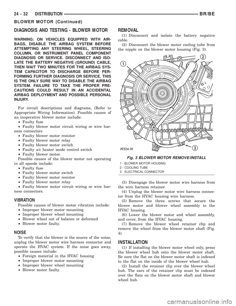
(2) Disconnect the blower motor cooling tube from
the nipple on the blower motor housing (Fig. 3).
(3) Disengage the blower motor wire harness from
the wire harness retainer.
(4) Unplug the blower motor wire harness connec-
tor from the HVAC housing wire harness.
(5) Remove the three screws that secure the
blower motor and blower wheel assembly to the
HVAC housing.
(6) Lower the blower motor and wheel assembly,
and cover, from the HVAC housing.
(7) Remove the blower wheel retainer clip and
remove the wheel from the blower motor shaft (Fig.
4).
INSTALLATION
(1) If installing the blower motor wheel only, press
the blower wheel hub onto the blower motor shaft.
Be sure the flat on the blower motor shaft is indexed
to the flat on the inside of the blower wheel hub.
(2) Install the retainer clip over the blower wheel
hub. The ears of the retainer clip must be indexed
over the flats on the blower motor shaft and blower
wheel hub.
Fig. 3 BLOWER MOTOR REMOVE/INSTALL
1 - BLOWER MOTOR HOUSING
2 - COOLING TUBE
3 - ELECTRICAL CONNECTOR
24 - 32 DISTRIBUTIONBR/BE
BLOWER MOTOR (Continued)
Page 2226 of 2255
CRANKSHAFT MAIN BEARINGS -
DESCRIPTION........................9-31
CRANKSHAFT MAIN BEARINGS -
INSTALLATION....................9-32,9-88
CRANKSHAFT MAIN BEARINGS -
OPERATION..........................9-31
CRANKSHAFT MAIN BEARINGS -
REMOVAL.......................9-31,9-88
CRANKSHAFT MAIN BEARINGS -
STANDARD PROCEDURE, FITTING........9-88
CRANKSHAFT OIL SEAL - FRONT -
DESCRIPTION........................9-32
CRANKSHAFT OIL SEAL - FRONT -
INSTALLATION...................9-160,9-32
CRANKSHAFT OIL SEAL - FRONT -
OPERATION..........................9-32
CRANKSHAFT OIL SEAL - FRONT -
REMOVAL......................9-160,9-32
CRANKSHAFT OIL SEAL - REAR -
DESCRIPTION........................9-33
CRANKSHAFT OIL SEAL - REAR -
INSTALLATION...............9-162,9-34,9-90
CRANKSHAFT OIL SEAL - REAR -
OPERATION..........................9-33
CRANKSHAFT OIL SEAL - REAR -
REMOVAL..................9-161,9-33,9-90
CRANKSHAFT REAR OIL SEAL RETAINER
- INSTALLATION.................9-163,9-90
CRANKSHAFT REAR OIL SEAL RETAINER
- REMOVAL.....................9-162,9-90
CROSSHEADS - CLEANING.............9-134
CROSSHEADS - INSPECTION...........9-135
CRUISE INDICATOR - DESCRIPTION.......8J-18
CRUISE INDICATOR - OPERATION.......8J-18
CUBBY BIN - INSTALLATION...........23-109
CUBBY BIN - REMOVAL..............23-108
CUP HOLDER - INSTALLATION.........23-110
CUP HOLDER - REMOVAL.............23-109
CUSHION - INSTALLATION, SEAT.......23-138
CUSHION - REMOVAL, SEAT...........23-138
CUSHION COVER - INSTALLATION, SEAT . 23-139
CUSHION COVER - REMOVAL, SEAT.....23-139
CUSHION COVER - SPLIT BENCH -
INSTALLATION, SEAT.................23-140
CUSHION COVER - SPLIT BENCH -
REMOVAL, SEAT....................23-139
CYLINDER - DESCRIPTION, MASTER......5-26
CYLINDER - DIAGNOSIS AND TESTING,
IGNITION SWITCH AND KEY LOCK........19-9
CYLINDER - INSTALLATION, LOCK.......23-74
CYLINDER - INSTALLATION, LOCK.......19-10
CYLINDER - INSTALLATION, MASTER.....5-28
CYLINDER - OPERATION, MASTER........5-26
CYLINDER - REMOVAL, LOCK...........23-74
CYLINDER - REMOVAL, LOCK...........19-10
CYLINDER - REMOVAL, MASTER.........5-27
CYLINDER BLEEDING - STANDARD
PROCEDURE, MASTER.................5-27
CYLINDER BLOCK REFACING -
STANDARD PROCEDURE...............9-148
CYLINDER BORE - DE-GLAZE -
STANDARD PROCEDURE...............9-148
CYLINDER BORE HONING - STANDARD
PROCEDURE.....................9-11,9-65
CYLINDER BORE REPAIR - STANDARD
PROCEDURE........................9-149
CYLINDER COMBUSTION PRESSURE
LEAKAGE - DIAGNOSIS AND TESTING
. . 9-64,9-9
CYLINDER COMPRESSION PRESSURE -
DIAGNOSIS AND TESTING
...........9-64,9-9
CYLINDER HEAD - CLEANING
.......9-134,9-77
CYLINDER HEAD - DESCRIPTION
. . . 9-130,9-20,
9-76
CYLINDER HEAD - INSPECTION
.....9-134,9-77
CYLINDER HEAD - INSTALLATION
........9-77
CYLINDER HEAD - OPERATION
...........9-21
CYLINDER HEAD - REMOVAL
.......9-130,9-76
CYLINDER HEAD COVER GASKET -
DESCRIPTION
........................9-20
CYLINDER HEAD COVER GASKET -
OPERATION
..........................9-21
CYLINDER HEAD COVER(S) - CLEANING
. . 9-137,
9-23,9-79
CYLINDER HEAD COVER(S) -
DESCRIPTION
........................9-78
CYLINDER HEAD COVER(S) -
INSPECTION
................9-138,9-23,9-79CYLINDER HEAD COVER(S) -
INSTALLATION...............9-138,9-23,9-79
CYLINDER HEAD COVER(S) - REMOVAL . . 9-137,
9-23,9-78
CYLINDER HEAD GASKET FAILURE -
DIAGNOSIS AND TESTING..........9-21,9-76
CYLINDER LOCK SWITCH -
DESCRIPTION, DOOR..................8N-5
CYLINDER LOCK SWITCH - DIAGNOSIS
AND TESTING, DOOR..................8N-6
CYLINDER LOCK SWITCH -
INSTALLATION, DOOR.................8N-6
CYLINDER LOCK SWITCH - OPERATION,
DOOR..............................8N-5
CYLINDER LOCK SWITCH - REMOVAL,
DOOR..............................8N-6
CYLINDER/POWER BOOSTER -
DIAGNOSIS AND TESTING, MASTER......5-26
DAM - INSTALLATION, FRONT AIR........13-2
DAM - REMOVAL, FRONT AIR...........13-2
DAMAGED OR WORN THREADS -
STANDARD PROCEDURE,
REPAIR ....................9-11,9-122,9-66
DAMPER - INSPECTION, VIBRATION.....9-172
DAMPER - INSTALLATION,
VIBRATION.................9-173,9-40,9-97
DAMPER - REMOVAL, VIBRATION . . . 9-172,9-40,
9-96
DANA 44 & 60 - REMOVAL..............2-19
DANA 44 AXLE - INSTALLATION......2-20,2-21
DANA 44 AXLE - REMOVAL.............2-21
DANA 60 AXLE - INSTALLATION.......2-20,2-22
DANA 60 AXLE - REMOVAL.............2-21
DATA BUS - DESCRIPTION, CCD..........8E-6
DATA BUS - DIAGNOSIS AND TESTING,
CCD ...............................8E-11
DATA BUS - OPERATION, CCD...........8E-7
DATA LINK CONNECTOR - DESCRIPTION . . 8E-12
DATA LINK CONNECTOR - OPERATION....8E-12
DATA PLATE - DESCRIPTION, ENGINE....9-129
DATA PLATE, SPECIFICATIONS - FUEL
INJECTION PUMP....................14-77
DAY / NIGHT MIRROR - DESCRIPTION,
AUTOMATIC........................8N-11
DAY / NIGHT MIRROR - INSTALLATION,
AUTOMATIC........................8N-13
DAY / NIGHT MIRROR - OPERATION,
AUTOMATIC........................8N-12
DAY / NIGHT MIRROR - REMOVAL,
AUTOMATIC........................8N-13
DAY/NIGHT MIRROR - DIAGNOSIS AND
TESTING, AUTOMATIC................8N-12
DAYTIME RUNNING LAMP MODULE -
DESCRIPTION........................8L-9
DAYTIME RUNNING LAMP MODULE -
INSTALLATION........................8L-9
DAYTIME RUNNING LAMP MODULE -
OPERATION..........................8L-9
DAYTIME RUNNING LAMP MODULE -
REMOVAL...........................8L-9
DECALS - INSTALLATION..............23-64
DECALS - INSTALLATION, BODY
STRIPES...........................23-87
DECALS - REMOVAL..................23-64
DECALS - REMOVAL, BODY STRIPES
.....23-87
DEFINITION - DESCRIPTION, TRIP
.......25-19
DEFROSTER AND DEMISTER DUCT
ADAPTER - INSTALLATION
.............24-33
DEFROSTER AND DEMISTER DUCT
ADAPTER - REMOVAL
.................24-33
DEFROSTER AND DEMISTER DUCTS -
INSTALLATION
.......................24-33
DEFROSTER AND DEMISTER DUCTS -
REMOVAL
..........................24-33
DE-GLAZE - STANDARD PROCEDURE,
CYLINDER BORE
.....................9-148
DELIVERY - SPECIFICATIONS, TORQUE -
FUEL
...............................14-4
DELIVERY SYSTEM - DESCRIPTION,
DIESEL FUEL
........................14-55
DELIVERY SYSTEM - DESCRIPTION,
FUEL
...............................14-2
DELIVERY SYSTEM - OPERATION, FUEL
. . . 14-2
DEMAGNETIZING - STANDARD
PROCEDURE, COMPASS
...............8M-5
DEMISTER DUCT ADAPTER -
INSTALLATION, DEFROSTER
............24-33DEMISTER DUCT ADAPTER - REMOVAL,
DEFROSTER.........................24-33
DEMISTER DUCTS - INSTALLATION,
DEFROSTER.........................24-33
DEMISTER DUCTS - INSTALLATION,
INSTRUMENT PANEL..................24-36
DEMISTER DUCTS - REMOVAL,
DEFROSTER.........................24-33
DEMISTER DUCTS - REMOVAL,
INSTRUMENT PANEL..................24-36
DEMISTER GRILLES - INSTALLATION.....24-31
DEMISTER GRILLES - REMOVAL........24-31
DEPLOYMENT - STANDARD
PROCEDURE, SERVICE AFTER AN
AIRBAG.............................8O-4
DETECTION PUMP - DESCRIPTION, LEAK . 25-34
DETECTION PUMP - INSTALLATION,
LEAK..............................25-34
DETECTION PUMP - OPERATION, LEAK . . . 25-34
DETECTION PUMP - REMOVAL, LEAK....25-34
DIAGRAMS - DESCRIPTION, HOW TO
USE WIRING......................8W-01-1
DIAGRAMS - HYDRAULIC SCHEMATICS,
SCHEMATICS.................21-132,21-302
DIESEL - CLEANING, RADIATOR - 5.9L....7-64
DIESEL - CLEANING, RADIATOR FAN -
5.9L................................7-43
DIESEL - CLEANING, WATER PUMP -
5.9L................................7-72
DIESEL - DESCRIPTION................25-1
DIESEL - DESCRIPTION........14-106,14-108
DIESEL - DESCRIPTION.................8I-6
DIESEL - DESCRIPTION, 5.9L............11-3
DIESEL - DESCRIPTION, BELT
TENSIONERS - 5.9L...................7-23
DIESEL - DESCRIPTION, COOLANT
RECOVERY CONTAINER - 3.9L/5.2L/
5.9L/5.9L............................7-40
DIESEL - DESCRIPTION, COOLING
SYSTEM FLOW - 5.9L...................7-2
DIESEL - DESCRIPTION, ENGINE 5.9L....9-115
DIESEL - DESCRIPTION, ENGINE BLOCK
HEATER - 5.9L........................7-46
DIESEL - DESCRIPTION, ENGINE
COOLANT THERMOSTAT - 5.9L...........7-53
DIESEL - DESCRIPTION, FAN DRIVE
VISCOUS CLUTCH - 5.9L...............7-56
DIESEL - DESCRIPTION, RADIATOR -
5.9L................................7-62
DIESEL - DESCRIPTION, TRANS COOLER
- 5.9L..............................7-84
DIESEL - DESCRIPTION, VACUUM PUMP
- 5.9L..............................7-33
DIESEL - DESCRIPTION, WATER PUMP -
5.9L................................7-72
DIESEL - FUEL INJECTOR FIRING ORDER . 14-62
DIESEL - INSPECTION, EXHAUST PIPE -
5.9L................................11-9
DIESEL - INSPECTION, RADIATOR - 5.9L . . . 7-64
DIESEL - INSPECTION, RADIATOR FAN -
5.9L................................7-43
DIESEL - INSPECTION, TAILPIPE - 5.9L . . . 11-12
DIESEL - INSPECTION, WATER PUMP -
5.9L................................7-72
DIESEL - INSTALLATION..............14-107
DIESEL - INSTALLATION................8I-9
DIESEL - INSTALLATION, BELT
TENSIONERS - 5.9L...................7-23
DIESEL - INSTALLATION, COOLANT
RECOVERY CONTAINER - 3.9L/5.2L/
5.9L/5.9L............................7-41
DIESEL - INSTALLATION, DRIVE BELTS -
5.9L................................7-32
DIESEL - INSTALLATION, ENGINE BLOCK
HEATER - 5.9L........................7-46
DIESEL - INSTALLATION, ENGINE
COOLANT THERMOSTAT - 5.9L...........7-54
DIESEL - INSTALLATION, EXHAUST PIPE
- 5.9L..............................11-9
DIESEL - INSTALLATION, MUFFLER -
5.9L
...............................11-11
DIESEL - INSTALLATION, RADIATOR -
5.9L
................................7-64
DIESEL - INSTALLATION, RADIATOR FAN
- 5.9L
..............................7-44
DIESEL - INSTALLATION, TAILPIPE - 5.9L
. 11-13
DIESEL - INSTALLATION, VACUUM
PUMP - 5.9L
.........................7-36
BR/BEINDEX 9
Description Group-Page Description Group-Page Description Group-Page