Page 1597 of 2399
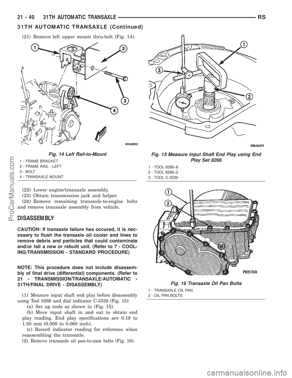
(21) Remove left upper mount thru-bolt (Fig. 14).
(22) Lower engine/transaxle assembly.
(23) Obtain transmission jack and helper.
(24) Remove remaining transaxle-to-engine bolts
and remove transaxle assembly from vehicle.
DISASSEMBLY
CAUTION: If transaxle failure has occured, it is nec-
essary to flush the transaxle oil cooler and lines to
remove debris and particles that could contaminate
and/or fail a new or rebuilt unit. (Refer to 7 - COOL-
ING/TRANSMISSION - STANDARD PROCEDURE)
NOTE: This procedure does not include disassem-
bly of final drive (differential) components. (Refer to
21 - TRANSMISSION/TRANSAXLE/AUTOMATIC -
31TH/FINAL DRIVE - DISASSEMBLY)
(1)
Measure input shaft end play before disassembly
using Tool 8266 and dial indicator C-3339 (Fig. 15):
(a) Set up tools as shown in (Fig. 15).
(b) Move input shaft in and out to obtain end
play reading. End play specifications are 0.19 to
1.50 mm (0.008 to 0.060 inch).
(c) Record indicator reading for reference when
reassembling the transaxle.
(2)
Remove transaxle oil pan-to-case bolts (Fig. 16).
Fig. 14 Left Rail-to-Mount
1 - FRAME BRACKET
2 - FRAME RAIL - LEFT
3 - BOLT
4 - TRANSAXLE MOUNT
Fig. 15 Measure Input Shaft End Play using End
Play Set 8266
1 - TOOL 8266±8
2 - TOOL 8266±2
3 - TOOL C-3339
Fig. 16 Transaxle Oil Pan Bolts
1 - TRANSAXLE OIL PAN
2 - OIL PAN BOLTS
21 - 40 31TH AUTOMATIC TRANSAXLERS
31TH AUTOMATIC TRANSAXLE (Continued)
ProCarManuals.com
Page 1603 of 2399
(23) Remove park sprag rod support-to-case bolts
(Fig. 37).
(24) Remove support and bolts (Fig. 38).
NOTE: To remove pawl, spring, and pivot shaft, the
governor support retainer must be removed. (Refer
to 21 - TRANSMISSION/TRANSAXLE/AUTOMATIC -
31TH/TRANSFER SYSTEM - REMOVAL)(25) Remove park pawl, spring, and pivot shaft
(Fig. 39).
(26) Remove oil pump-to-transaxle case bolts (Fig.
40).
Fig. 37 Parking Sprag Rod Support
1 - PARKING SPRAG ROD SUPPORT
2 - BOLT (2)
3 - OUTPUT SHAFT GEAR
Fig. 38 Support and Bolts
1 - BOLT (2)
2 - PARKING SPRAG ROD SUPPORT
Fig. 39 Parking Pawl, Return Spring, and Pivot Shaft
1 - PARK PAWL
2 - RETURN SPRING
3 - NOTE: SMALL DIAMETER TO REAR
4 - PIVOT SHAFT
Fig. 40 Oil Pump Attaching Bolts
1 - SEAL
2 - PUMP ATTACHING BOLTS (7)
3 - PUMP HOUSING
21 - 46 31TH AUTOMATIC TRANSAXLERS
31TH AUTOMATIC TRANSAXLE (Continued)
ProCarManuals.com
Page 1608 of 2399
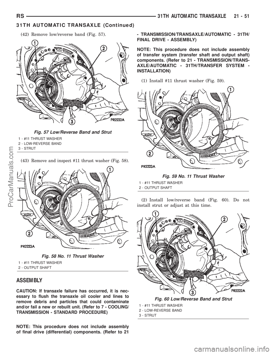
(42) Remove low/reverse band (Fig. 57).
(43)
Remove and inspect #11 thrust washer (Fig. 58).
ASSEMBLY
CAUTION: If transaxle failure has occurred, it is nec-
essary to flush the transaxle oil cooler and lines to
remove debris and particles that could contaminate
and/or fail a new or rebuilt unit. (Refer to 7 - COOLING/
TRANSMISSION - STANDARD PROCEDURE)
NOTE: This procedure does not include assembly
of final drive (differential) components. (Refer to 21- TRANSMISSION/TRANSAXLE/AUTOMATIC - 31TH/
FINAL DRIVE - ASSEMBLY)
NOTE: This procedure does not include assembly
of transfer system (transfer shaft and output shaft)
components. (Refer to 21 - TRANSMISSION/TRANS-
AXLE/AUTOMATIC - 31TH/TRANSFER SYSTEM -
INSTALLATION)
(1) Install #11 thrust washer (Fig. 59).
(2) Install low/reverse band (Fig. 60). Do not
install strut or adjust at this time.
Fig. 57 Low/Reverse Band and Strut
1 - #11 THRUST WASHER
2 - LOW-REVERSE BAND
3 - STRUT
Fig. 58 No. 11 Thrust Washer
1 - #11 THRUST WASHER
2 - OUTPUT SHAFT
Fig. 59 No. 11 Thrust Washer
1 - #11 THRUST WASHER
2 - OUTPUT SHAFT
Fig. 60 Low/Reverse Band and Strut
1 - #11 THRUST WASHER
2 - LOW-REVERSE BAND
3 - STRUT
RS31TH AUTOMATIC TRANSAXLE21-51
31TH AUTOMATIC TRANSAXLE (Continued)
ProCarManuals.com
Page 1618 of 2399
INSTALLATION
(1) Install transaxle assembly to engine using a
transmission jack and helper.
(2) Install and torque transaxle-to-engine bolts to
95 N´m (70 ft. lbs.).
(3) Using screw jack and wood block, raise engine/
transaxle assembly into position and install left
upper mount thru-bolt (Fig. 97). Torque bolt to 75
N´m (55 ft. lbs.).
(4) Install left wheel splash shield.
(5) Install torque converter-to-drive plate bolts and
torque to 88 N´m (65 ft. lbs.).
(6) Install rear mount bracket to transaxle (Fig.
98). Install bolts by hand but do not tighten at this
time.
(7) Align rear mount bracket to mount and install
thru-bolt. Do not tighten at this time.
(8) Connect vehicle speed sensor connector.
Fig. 97 Left Mount-to-Rail
1 - FRAME BRACKET
2 - FRAME RAIL - LEFT
3 - BOLT
4 - TRANSAXLE MOUNT
Fig. 98 Rear Mount Bracket
1 - BOLT - VERTICAL
2 - BRACKET - REAR MOUNT3 - BOLT - HORIZONTAL
RS31TH AUTOMATIC TRANSAXLE21-61
31TH AUTOMATIC TRANSAXLE (Continued)
ProCarManuals.com
Page 1620 of 2399
(13) Install halfshafts. (Refer to 3 - DIFFEREN-
TIAL & DRIVELINE/HALF SHAFT - INSTALLA-
TION)
(14) Lower vehicle.
(15) Torque rear mount bracket-to-transaxle verti-
cal bolts (Fig. 98) to 102 N´m (75 ft. lbs.).
(16) Connect back up lamp switch connector.
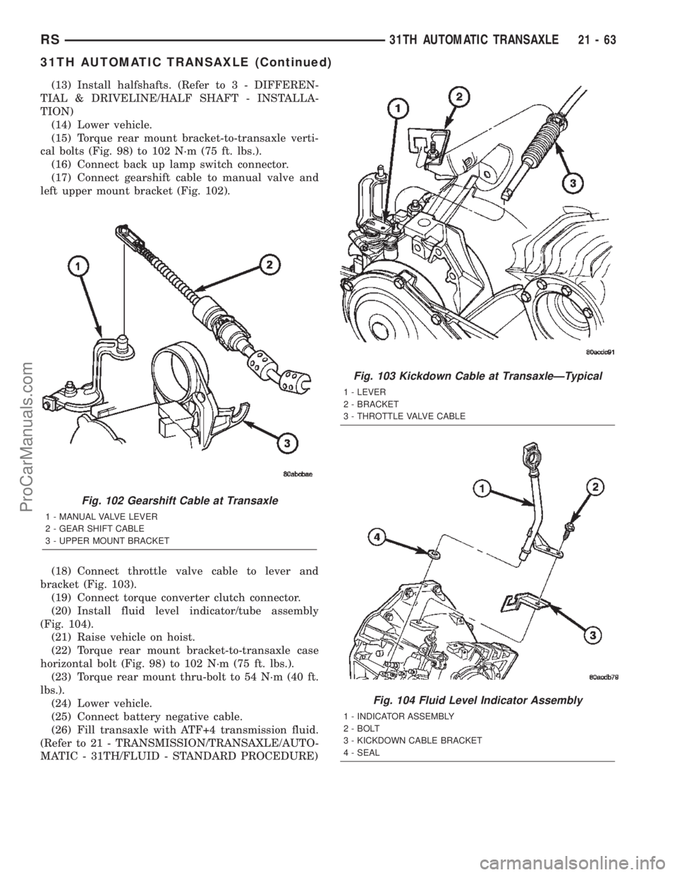
(17) Connect gearshift cable to manual valve and
left upper mount bracket (Fig. 102).
(18) Connect throttle valve cable to lever and
bracket (Fig. 103).
(19) Connect torque converter clutch connector.
(20) Install fluid level indicator/tube assembly
(Fig. 104).
(21) Raise vehicle on hoist.
(22) Torque rear mount bracket-to-transaxle case
horizontal bolt (Fig. 98) to 102 N´m (75 ft. lbs.).
(23) Torque rear mount thru-bolt to 54 N´m (40 ft.
lbs.).
(24) Lower vehicle.
(25) Connect battery negative cable.
(26) Fill transaxle with ATF+4 transmission fluid.
(Refer to 21 - TRANSMISSION/TRANSAXLE/AUTO-
MATIC - 31TH/FLUID - STANDARD PROCEDURE)
Fig. 102 Gearshift Cable at Transaxle
1 - MANUAL VALVE LEVER
2 - GEAR SHIFT CABLE
3 - UPPER MOUNT BRACKET
Fig. 103 Kickdown Cable at TransaxleÐTypical
1 - LEVER
2 - BRACKET
3 - THROTTLE VALVE CABLE
Fig. 104 Fluid Level Indicator Assembly
1 - INDICATOR ASSEMBLY
2 - BOLT
3 - KICKDOWN CABLE BRACKET
4 - SEAL
RS31TH AUTOMATIC TRANSAXLE21-63
31TH AUTOMATIC TRANSAXLE (Continued)
ProCarManuals.com
Page 1636 of 2399
ACCUMULATOR
DESCRIPTION
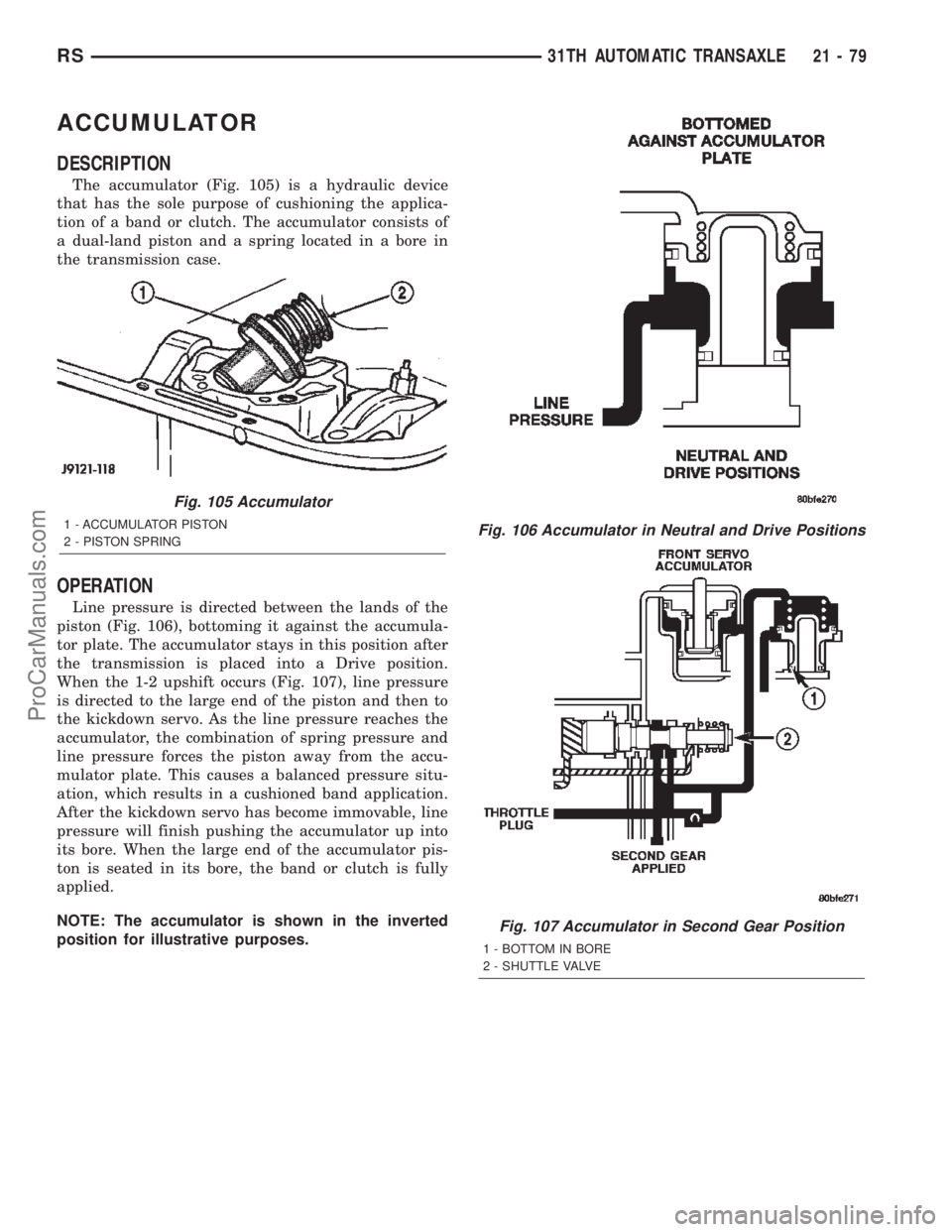
The accumulator (Fig. 105) is a hydraulic device
that has the sole purpose of cushioning the applica-
tion of a band or clutch. The accumulator consists of
a dual-land piston and a spring located in a bore in
the transmission case.
OPERATION
Line pressure is directed between the lands of the
piston (Fig. 106), bottoming it against the accumula-
tor plate. The accumulator stays in this position after
the transmission is placed into a Drive position.
When the 1-2 upshift occurs (Fig. 107), line pressure
is directed to the large end of the piston and then to
the kickdown servo. As the line pressure reaches the
accumulator, the combination of spring pressure and
line pressure forces the piston away from the accu-
mulator plate. This causes a balanced pressure situ-
ation, which results in a cushioned band application.
After the kickdown servo has become immovable, line
pressure will finish pushing the accumulator up into
its bore. When the large end of the accumulator pis-
ton is seated in its bore, the band or clutch is fully
applied.
NOTE: The accumulator is shown in the inverted
position for illustrative purposes.
Fig. 105 Accumulator
1 - ACCUMULATOR PISTON
2 - PISTON SPRINGFig. 106 Accumulator in Neutral and Drive Positions
Fig. 107 Accumulator in Second Gear Position
1 - BOTTOM IN BORE
2 - SHUTTLE VALVE
RS31TH AUTOMATIC TRANSAXLE21-79
ProCarManuals.com
Page 1637 of 2399
BANDS
DESCRIPTION
KICKDOWN (FRONT) BAND
DESCRIPTION
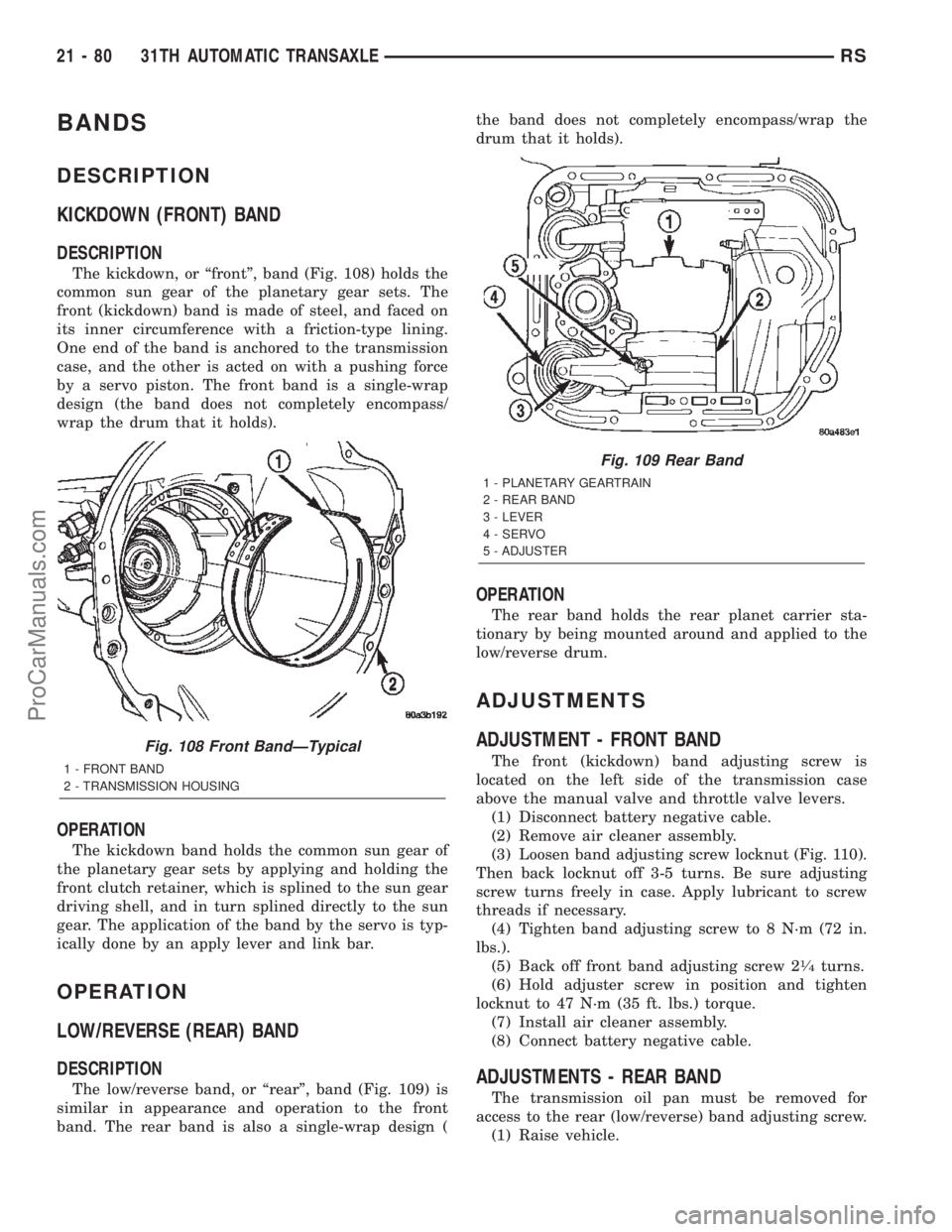
The kickdown, or ªfrontº, band (Fig. 108) holds the
common sun gear of the planetary gear sets. The
front (kickdown) band is made of steel, and faced on
its inner circumference with a friction-type lining.
One end of the band is anchored to the transmission
case, and the other is acted on with a pushing force
by a servo piston. The front band is a single-wrap
design (the band does not completely encompass/
wrap the drum that it holds).
OPERATION
The kickdown band holds the common sun gear of
the planetary gear sets by applying and holding the
front clutch retainer, which is splined to the sun gear
driving shell, and in turn splined directly to the sun
gear. The application of the band by the servo is typ-
ically done by an apply lever and link bar.
OPERATION
LOW/REVERSE (REAR) BAND
DESCRIPTION
The low/reverse band, or ªrearº, band (Fig. 109) is
similar in appearance and operation to the front
band. The rear band is also a single-wrap design (the band does not completely encompass/wrap the
drum that it holds).
OPERATION
The rear band holds the rear planet carrier sta-
tionary by being mounted around and applied to the
low/reverse drum.
ADJUSTMENTS
ADJUSTMENT - FRONT BAND
The front (kickdown) band adjusting screw is
located on the left side of the transmission case
above the manual valve and throttle valve levers.
(1) Disconnect battery negative cable.
(2) Remove air cleaner assembly.
(3) Loosen band adjusting screw locknut (Fig. 110).
Then back locknut off 3-5 turns. Be sure adjusting
screw turns freely in case. Apply lubricant to screw
threads if necessary.
(4) Tighten band adjusting screw to 8 N´m (72 in.
lbs.).
(5) Back off front band adjusting screw 2
1¤4turns.
(6) Hold adjuster screw in position and tighten
locknut to 47 N´m (35 ft. lbs.) torque.
(7) Install air cleaner assembly.
(8) Connect battery negative cable.
ADJUSTMENTS - REAR BAND
The transmission oil pan must be removed for
access to the rear (low/reverse) band adjusting screw.
(1) Raise vehicle.
Fig. 108 Front BandÐTypical
1 - FRONT BAND
2 - TRANSMISSION HOUSING
Fig. 109 Rear Band
1 - PLANETARY GEARTRAIN
2 - REAR BAND
3 - LEVER
4 - SERVO
5 - ADJUSTER
21 - 80 31TH AUTOMATIC TRANSAXLERS
ProCarManuals.com
Page 1638 of 2399
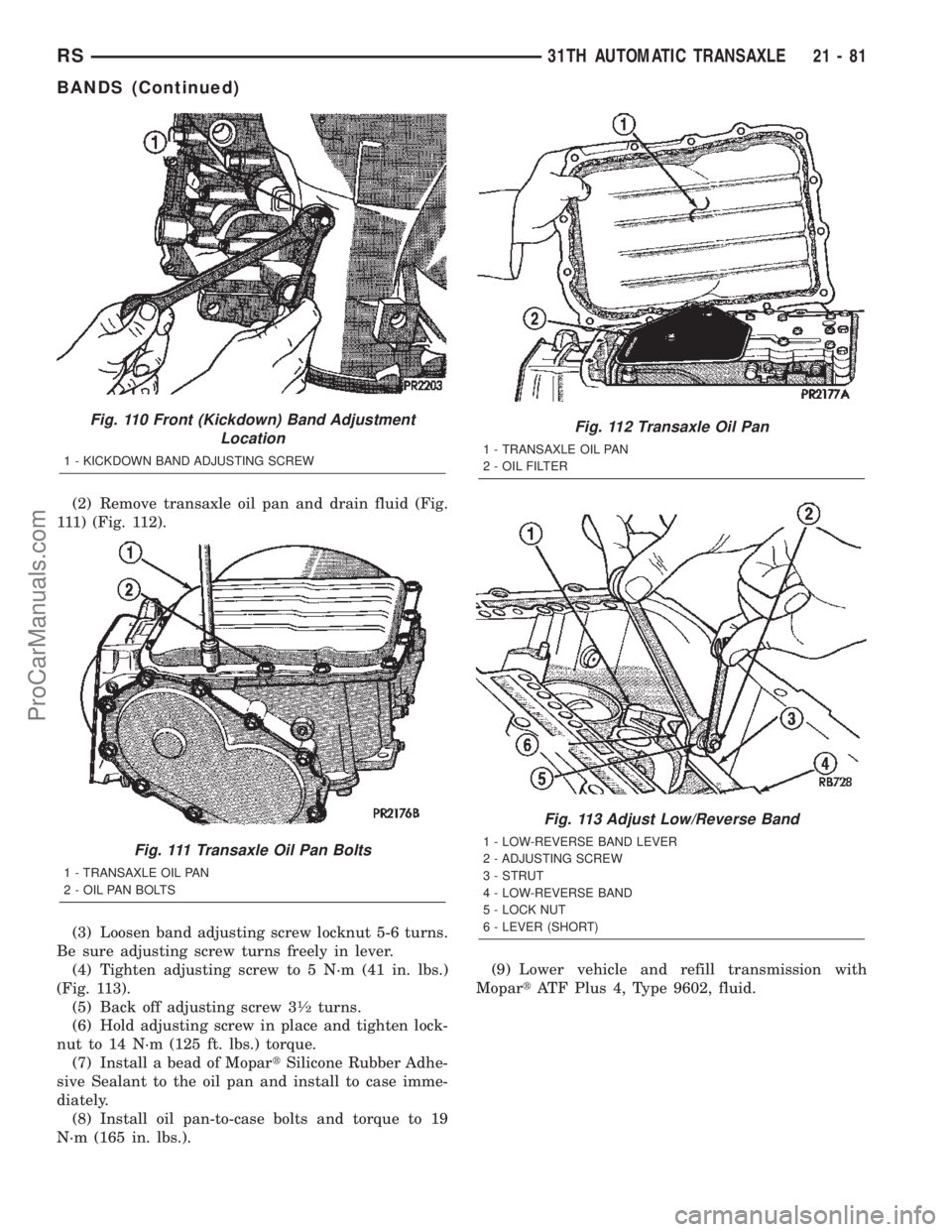
(2) Remove transaxle oil pan and drain fluid (Fig.
111) (Fig. 112).
(3) Loosen band adjusting screw locknut 5-6 turns.
Be sure adjusting screw turns freely in lever.
(4) Tighten adjusting screw to 5 N´m (41 in. lbs.)
(Fig. 113).
(5) Back off adjusting screw 3
1¤2turns.
(6) Hold adjusting screw in place and tighten lock-
nut to 14 N´m (125 ft. lbs.) torque.
(7) Install a bead of MopartSilicone Rubber Adhe-
sive Sealant to the oil pan and install to case imme-
diately.
(8) Install oil pan-to-case bolts and torque to 19
N´m (165 in. lbs.).(9) Lower vehicle and refill transmission with
MopartATF Plus 4, Type 9602, fluid.
Fig. 110 Front (Kickdown) Band Adjustment
Location
1 - KICKDOWN BAND ADJUSTING SCREW
Fig. 111 Transaxle Oil Pan Bolts
1 - TRANSAXLE OIL PAN
2 - OIL PAN BOLTS
Fig. 112 Transaxle Oil Pan
1 - TRANSAXLE OIL PAN
2 - OIL FILTER
Fig. 113 Adjust Low/Reverse Band
1 - LOW-REVERSE BAND LEVER
2 - ADJUSTING SCREW
3 - STRUT
4 - LOW-REVERSE BAND
5 - LOCK NUT
6 - LEVER (SHORT)
RS31TH AUTOMATIC TRANSAXLE21-81
BANDS (Continued)
ProCarManuals.com