2002 CHRYSLER CARAVAN automatic transmission
[x] Cancel search: automatic transmissionPage 1547 of 2399
NOTE: Before installing power steering pressure
hose on power steering pump, inspect the O-ring
on the power steering pressure hose for damage
and replace if required.
(4) Install the power steering fluid pressure hose
fitting into the pressure port of the power steering
pump (Fig. 12). Tighten the pressure line to pump
fitting tube nut to a torque of 31 N´m (275 in. lbs.).
(5) Install the power steering fluid supply hose on
the power steering pump supply fitting (Fig. 12).Be
sure hose clamp is properly reinstalled.
(6) Install the accessary drive belt (Refer to 7 -
COOLING/ACCESSORY DRIVE/DRIVE BELTS -
INSTALLATION).
(7) Install the splash shields below the engine
compartment.
(8) Lower the vehicle.
(9) Connect the negative (-) battery cable on the
negative battery post.
(10) Fill and bleed the power steering system
using the Power Steering Pump Initial Operation
Procedure (Refer to 19 - STEERING/PUMP - STAN-
DARD PROCEDURE).
(11) Inspect for leaks.
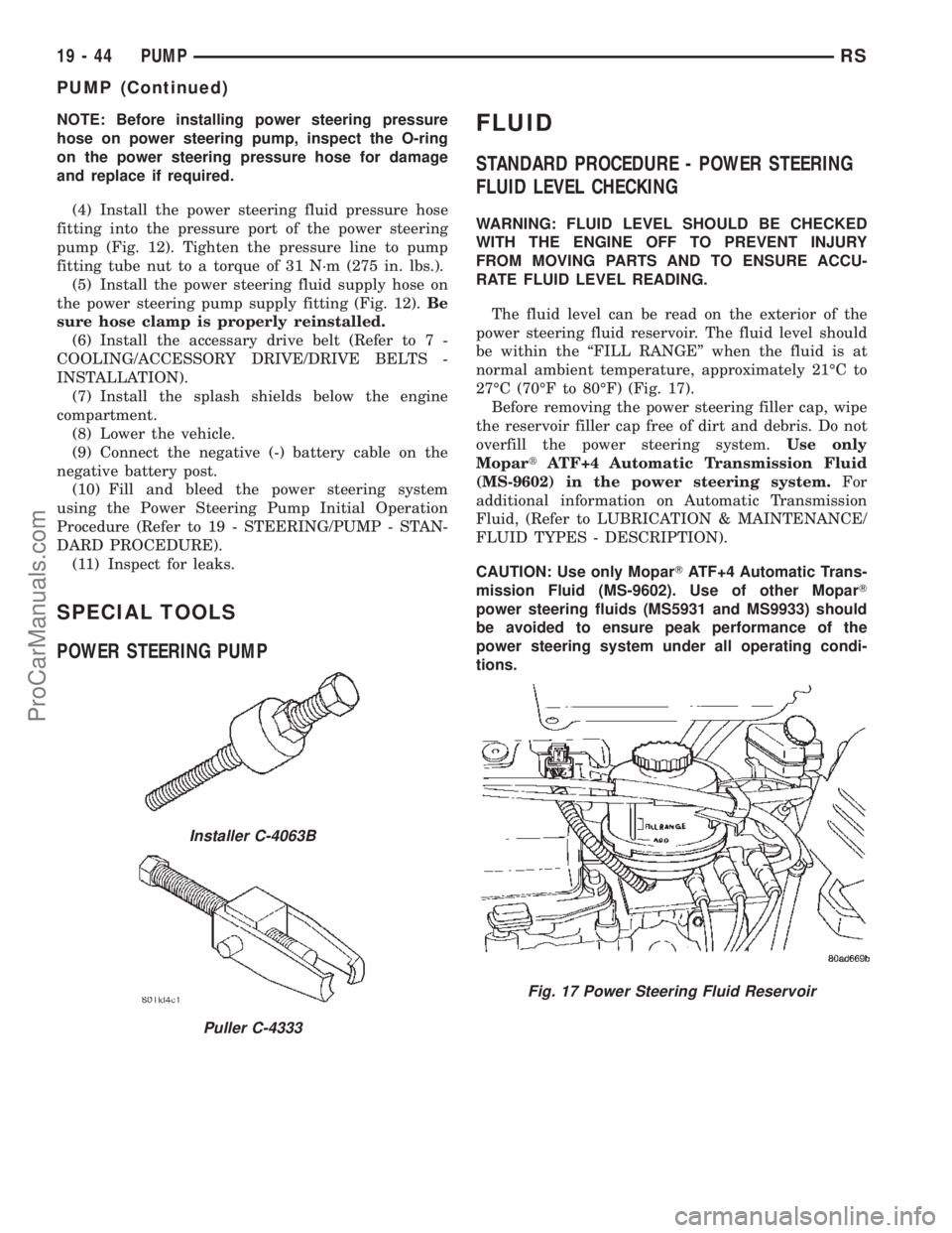
SPECIAL TOOLS
POWER STEERING PUMP
FLUID
STANDARD PROCEDURE - POWER STEERING
FLUID LEVEL CHECKING
WARNING: FLUID LEVEL SHOULD BE CHECKED
WITH THE ENGINE OFF TO PREVENT INJURY
FROM MOVING PARTS AND TO ENSURE ACCU-
RATE FLUID LEVEL READING.
The fluid level can be read on the exterior of the
power steering fluid reservoir. The fluid level should
be within the ªFILL RANGEº when the fluid is at
normal ambient temperature, approximately 21ÉC to
27ÉC (70ÉF to 80ÉF) (Fig. 17).
Before removing the power steering filler cap, wipe
the reservoir filler cap free of dirt and debris. Do not
overfill the power steering system.Use only
MopartATF+4 Automatic Transmission Fluid
(MS-9602) in the power steering system.For
additional information on Automatic Transmission
Fluid, (Refer to LUBRICATION & MAINTENANCE/
FLUID TYPES - DESCRIPTION).
CAUTION: Use only MoparTATF+4 Automatic Trans-
mission Fluid (MS-9602). Use of other MoparT
power steering fluids (MS5931 and MS9933) should
be avoided to ensure peak performance of the
power steering system under all operating condi-
tions.
Installer C-4063B
Puller C-4333
Fig. 17 Power Steering Fluid Reservoir
19 - 44 PUMPRS
PUMP (Continued)
ProCarManuals.com
Page 1558 of 2399
TRANSMISSION/TRANSAXLE
TABLE OF CONTENTS
page page
POWER TRANSFER UNIT..................1
31TH AUTOMATIC TRANSAXLE.............2141TE AUTOMATIC TRANSAXLE............161
T850 MANUAL TRANSAXLE...............308
POWER TRANSFER UNIT
TABLE OF CONTENTS
page page
POWER TRANSFER UNIT
DESCRIPTION..........................1
OPERATION............................3
DIAGNOSIS AND TESTING
SEAL IDENTIFICATION..................3
FLUID LEAK DIAGNOSIS................4
STANDARD PROCEDURE
STANDARD PROCEDURE - FLUID LEVEL
INSPECTION..........................5
STANDARD PROCEDURE - PTU FLUID
CHANGE.............................5
REMOVAL.............................6
INSTALLATION..........................7
ADJUSTMENTS
OUTPUT FLANGE SHIM SELECTION.......7
SPECIFICATIONS
TORQUE.............................8
SPECIAL TOOLS
SDP POWER TRANSFER UNIT............8
DIFFERENTIAL CARRIER SEAL
REMOVAL.............................9
INSTALLATION..........................9
END COVER BALL BEARING
REMOVAL.............................9INSTALLATION.........................10
END COVER SEAL
REMOVAL.............................11
INSTALLATION.........................11
HALF SHAFT INNER SEAL
REMOVAL.............................12
INSTALLATION.........................13
INPUT SHAFT COVER SEAL
REMOVAL.............................13
INSTALLATION.........................14
INPUT SHAFT END SEAL
REMOVAL.............................16
INSTALLATION.........................16
INPUT SHAFT SEAL
REMOVAL.............................17
INSTALLATION.........................18
OUTER HALF SHAFT SEAL
REMOVAL.............................19
INSTALLATION.........................19
REAR COVER O-RING
REMOVAL.............................19
INSTALLATION.........................20
POWER TRANSFER UNIT
DESCRIPTION
The Power Transfer Unit (P.T.U.) is attached to a
modified automatic transaxle case where the right
half shaft extension housing would normally be
located.
The Power Transfer Unit is sealed from the trans-
axle and has its own oil sump. The Unit uses MopartSAE 80W-90 Gear and Axle Lubricant (MS-9020) and
holds 1.15 liters (1.22 quarts).
Service of the Power Transfer Unit is limited to:
²Fluid Change
²Seals
²Gaskets
²One ball bearing
²Output flange
If the ring gear and pinion, any tapered roller
bearings, case, covers, or pinion carrier fail the entire
unit must be replaced.
RSTRANSMISSION/TRANSAXLE21-1
ProCarManuals.com
Page 1579 of 2399
ASSEMBLY...........................115
SHIFT INTERLOCK SOLENOID
DESCRIPTION........................115
OPERATION..........................115
DIAGNOSIS AND TESTING - BRAKE/
TRANSMISSION SHIFT INTERLOCK
SOLENOID..........................117
REMOVAL............................117
INSTALLATION........................118
SOLENOID - TCC
DESCRIPTION........................119
OPERATION..........................119
REMOVAL............................119
INSTALLATION........................120
THROTTLE VALVE CABLE
REMOVAL............................120
INSTALLATION........................121
ADJUSTMENTS
THROTTLE VALVE LINKAGE
ADJUSTMENT.......................122
TORQUE CONVERTER
DESCRIPTION........................122
OPERATION..........................126
REMOVAL............................127
INSTALLATION........................127
TRANSFER SYSTEM - OUTPUT SHAFT/GEAR/
BEARING
REMOVAL............................128INSTALLATION........................131
ADJUSTMENTS
ADJUSTMENT - OUTPUT SHAFT BEARING . 135
TRANSFER SYSTEM - TRANSFER SHAFT/
GEAR/BEARING
REMOVAL............................137
INSTALLATION........................141
ADJUSTMENTS
ADJUSTMENT - TRANSFER SHAFT
BEARING...........................145
VALVE BODY
REMOVAL............................146
DISASSEMBLY........................148
CLEANING...........................154
INSPECTION.........................155
ASSEMBLY...........................155
INSTALLATION........................158
ADJUSTMENTS
HYDRAULIC CONTROL PRESSURE
ADJUSTMENTS......................160
VEHICLE SPEED SENSOR/PINION GEAR
REMOVAL............................160
INSTALLATION........................160
31TH AUTOMATIC
TRANSAXLE
DESCRIPTION
This transaxle combines torque converter, three
speed transmission, final drive gearing, and differen-
tial into a front wheel drive system.
Within this transaxle, there are three primary
areas:
(1) Main center line plus valve body.
(2) Transfer shaft center line (includes governor
and parking sprag).
(3) Differential center line.
Center distances between the main rotating parts
in these three areas are held precise to maintain a
low noise level.
The torque converter, transaxle area, and differen-
tial are housed in an integral aluminum die casting.
The differential oil sump is common with the
transaxle sump. Separate filling of the differen-
tial is NOT necessary.
The torque converter is attached to the crankshaft
through a flexible driving plate. Cooling of the con-
verter is accomplished by circulating the transaxle
fluid through a remote cooler. There are two types of
coolers used. An oil-to-water type cooler located in
the radiator side tank and/or an oil-to-air heatexchanger. The torque converter assembly is a sealed
unit that cannot be disassembled.
The transaxle fluid is filtered by an internal filter
attached to the lower side of the valve body assembly.
Engine torque is transmitted to the torque con-
verter and then through the input shaft to multiple-
disc clutches in the transaxle. The power flow
depends on the application of the clutches and bands.
Refer to Elements in Use Chart in Diagnosis and
Tests section.
The transaxle consists of:
²Two multiple-disc clutches
²An overrunning clutch
²Two servos
²A hydraulic accumulator
²Two bands
²Two planetary gear sets
This provides three forward ratios and a reverse
ratio. The common sun gear of the planetary gear
sets is connected to the front clutch by a driving
shell. The driving shell is splined to the sun gear and
front clutch retainer. The hydraulic system consists
of an oil pump and a single valve body which con-
tains all of the valves except the governor valves.
The transaxle sump and differential sump are both
vented through the dipstick. Output torque from the
main center line is delivered through helical gears to
the transfer shaft. This gear set is a factor in the
transaxle final drive (axle) ratio. The shaft also car-
21 - 22 31TH AUTOMATIC TRANSAXLERS
ProCarManuals.com
Page 1581 of 2399
ries the governor and parking sprag. An integral heli-
cal gear on the transfer shaft drives the differential
ring gear.
OPERATION
Transmission output is directed to an integral dif-
ferential by a transfer gear system in the following
input-to-output ratios:
FIRST 2.69:1
SECOND 1.55:1
THIRD 1.00:1
REVERSE 2.10:1
DIAGNOSIS AND TESTING
DIAGNOSIS AND TESTING - PRELIMINARY
DIAGNOSIS
Automatic transaxle malfunctions are usually
caused by the following general conditions:
²Improper fluid level/condition²Poor engine performance
²Improper engine or transaxle adjustments
²Transaxle hydraulic malfunctions
²Transaxle mechanical malfunctions
Diagnosis of transaxle problems should always
begin with checking the easily accessible variables:
²Fluid level and condition
²Gearshift cable adjustment
²Throttle valve cable adjustment
After verifying or adjusting these variables, road
test the vehicle to determine if the problem has been
corrected or that further diagnosis is necessary. If the
problem still exists, refer to the following diagnosis
charts to aid in determining the source or cause of
failure.
Hydraulic pressure tests should be performed
when a transaxle internal failure is suspected. The
hydraulic flow charts, in the Schematics and Dia-
grams section of this group, outline fluid flow and
hydraulic circuitry. Circuit operation is provided for
all gear ranges. Normal working pressures are also
supplied for each of the gear ranges.
21 - 24 31TH AUTOMATIC TRANSAXLERS
31TH AUTOMATIC TRANSAXLE (Continued)
ProCarManuals.com
Page 1582 of 2399
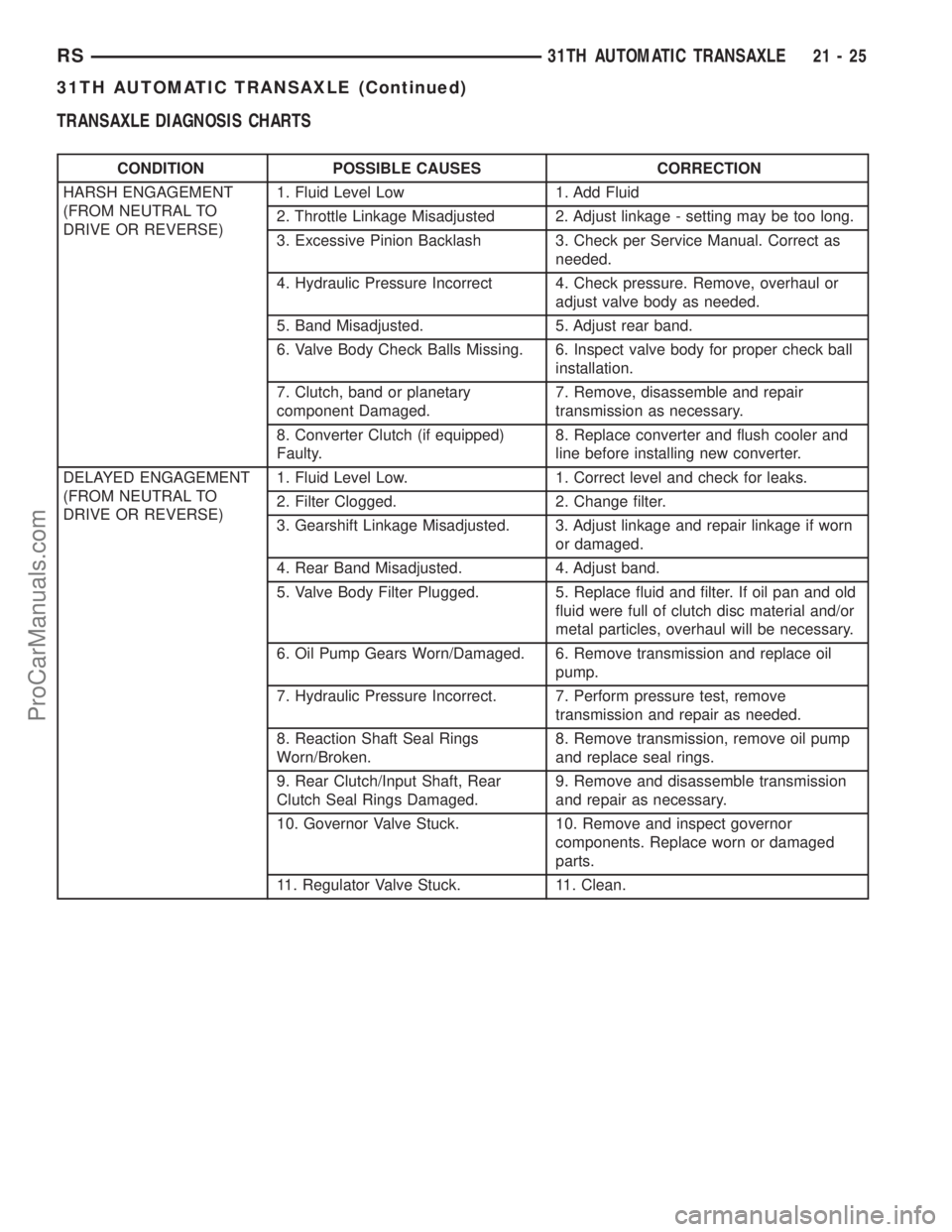
TRANSAXLE DIAGNOSIS CHARTS
CONDITION POSSIBLE CAUSES CORRECTION
HARSH ENGAGEMENT
(FROM NEUTRAL TO
DRIVE OR REVERSE)1. Fluid Level Low 1. Add Fluid
2. Throttle Linkage Misadjusted 2. Adjust linkage - setting may be too long.
3. Excessive Pinion Backlash 3. Check per Service Manual. Correct as
needed.
4. Hydraulic Pressure Incorrect 4. Check pressure. Remove, overhaul or
adjust valve body as needed.
5. Band Misadjusted. 5. Adjust rear band.
6. Valve Body Check Balls Missing. 6. Inspect valve body for proper check ball
installation.
7. Clutch, band or planetary
component Damaged.7. Remove, disassemble and repair
transmission as necessary.
8. Converter Clutch (if equipped)
Faulty.8. Replace converter and flush cooler and
line before installing new converter.
DELAYED ENGAGEMENT
(FROM NEUTRAL TO
DRIVE OR REVERSE)1. Fluid Level Low. 1. Correct level and check for leaks.
2. Filter Clogged. 2. Change filter.
3. Gearshift Linkage Misadjusted. 3. Adjust linkage and repair linkage if worn
or damaged.
4. Rear Band Misadjusted. 4. Adjust band.
5. Valve Body Filter Plugged. 5. Replace fluid and filter. If oil pan and old
fluid were full of clutch disc material and/or
metal particles, overhaul will be necessary.
6. Oil Pump Gears Worn/Damaged. 6. Remove transmission and replace oil
pump.
7. Hydraulic Pressure Incorrect. 7. Perform pressure test, remove
transmission and repair as needed.
8. Reaction Shaft Seal Rings
Worn/Broken.8. Remove transmission, remove oil pump
and replace seal rings.
9. Rear Clutch/Input Shaft, Rear
Clutch Seal Rings Damaged.9. Remove and disassemble transmission
and repair as necessary.
10. Governor Valve Stuck. 10. Remove and inspect governor
components. Replace worn or damaged
parts.
11. Regulator Valve Stuck. 11. Clean.
RS31TH AUTOMATIC TRANSAXLE21-25
31TH AUTOMATIC TRANSAXLE (Continued)
ProCarManuals.com
Page 1583 of 2399
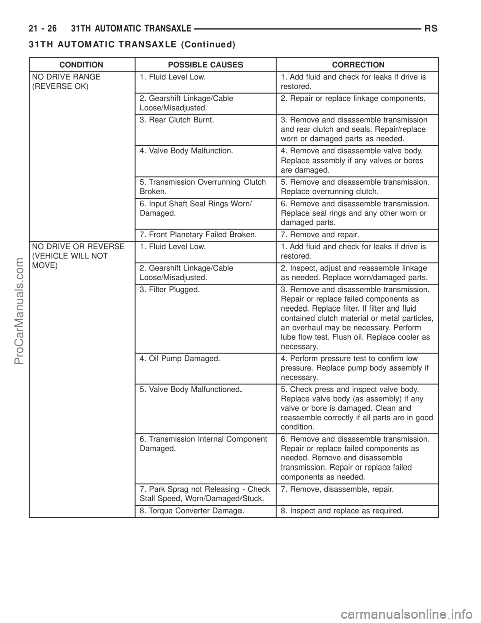
CONDITION POSSIBLE CAUSES CORRECTION
NO DRIVE RANGE
(REVERSE OK)1. Fluid Level Low. 1. Add fluid and check for leaks if drive is
restored.
2. Gearshift Linkage/Cable
Loose/Misadjusted.2. Repair or replace linkage components.
3. Rear Clutch Burnt. 3. Remove and disassemble transmission
and rear clutch and seals. Repair/replace
worn or damaged parts as needed.
4. Valve Body Malfunction. 4. Remove and disassemble valve body.
Replace assembly if any valves or bores
are damaged.
5. Transmission Overrunning Clutch
Broken.5. Remove and disassemble transmission.
Replace overrunning clutch.
6. Input Shaft Seal Rings Worn/
Damaged.6. Remove and disassemble transmission.
Replace seal rings and any other worn or
damaged parts.
7. Front Planetary Failed Broken. 7. Remove and repair.
NO DRIVE OR REVERSE
(VEHICLE WILL NOT
MOVE)1. Fluid Level Low. 1. Add fluid and check for leaks if drive is
restored.
2. Gearshift Linkage/Cable
Loose/Misadjusted.2. Inspect, adjust and reassemble linkage
as needed. Replace worn/damaged parts.
3. Filter Plugged. 3. Remove and disassemble transmission.
Repair or replace failed components as
needed. Replace filter. If filter and fluid
contained clutch material or metal particles,
an overhaul may be necessary. Perform
lube flow test. Flush oil. Replace cooler as
necessary.
4. Oil Pump Damaged. 4. Perform pressure test to confirm low
pressure. Replace pump body assembly if
necessary.
5. Valve Body Malfunctioned. 5. Check press and inspect valve body.
Replace valve body (as assembly) if any
valve or bore is damaged. Clean and
reassemble correctly if all parts are in good
condition.
6. Transmission Internal Component
Damaged.6. Remove and disassemble transmission.
Repair or replace failed components as
needed. Remove and disassemble
transmission. Repair or replace failed
components as needed.
7. Park Sprag not Releasing - Check
Stall Speed, Worn/Damaged/Stuck.7. Remove, disassemble, repair.
8. Torque Converter Damage. 8. Inspect and replace as required.
21 - 26 31TH AUTOMATIC TRANSAXLERS
31TH AUTOMATIC TRANSAXLE (Continued)
ProCarManuals.com
Page 1584 of 2399
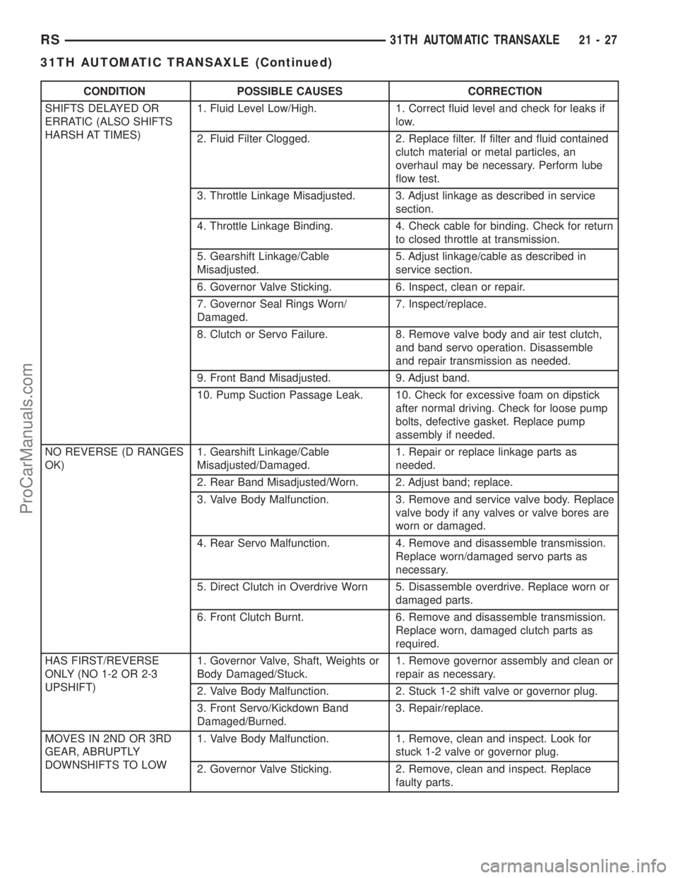
CONDITION POSSIBLE CAUSES CORRECTION
SHIFTS DELAYED OR
ERRATIC (ALSO SHIFTS
HARSH AT TIMES)1. Fluid Level Low/High. 1. Correct fluid level and check for leaks if
low.
2. Fluid Filter Clogged. 2. Replace filter. If filter and fluid contained
clutch material or metal particles, an
overhaul may be necessary. Perform lube
flow test.
3. Throttle Linkage Misadjusted. 3. Adjust linkage as described in service
section.
4. Throttle Linkage Binding. 4. Check cable for binding. Check for return
to closed throttle at transmission.
5. Gearshift Linkage/Cable
Misadjusted.5. Adjust linkage/cable as described in
service section.
6. Governor Valve Sticking. 6. Inspect, clean or repair.
7. Governor Seal Rings Worn/
Damaged.7. Inspect/replace.
8. Clutch or Servo Failure. 8. Remove valve body and air test clutch,
and band servo operation. Disassemble
and repair transmission as needed.
9. Front Band Misadjusted. 9. Adjust band.
10. Pump Suction Passage Leak. 10. Check for excessive foam on dipstick
after normal driving. Check for loose pump
bolts, defective gasket. Replace pump
assembly if needed.
NO REVERSE (D RANGES
OK)1. Gearshift Linkage/Cable
Misadjusted/Damaged.1. Repair or replace linkage parts as
needed.
2. Rear Band Misadjusted/Worn. 2. Adjust band; replace.
3. Valve Body Malfunction. 3. Remove and service valve body. Replace
valve body if any valves or valve bores are
worn or damaged.
4. Rear Servo Malfunction. 4. Remove and disassemble transmission.
Replace worn/damaged servo parts as
necessary.
5. Direct Clutch in Overdrive Worn 5. Disassemble overdrive. Replace worn or
damaged parts.
6. Front Clutch Burnt. 6. Remove and disassemble transmission.
Replace worn, damaged clutch parts as
required.
HAS FIRST/REVERSE
ONLY (NO 1-2 OR 2-3
UPSHIFT)1. Governor Valve, Shaft, Weights or
Body Damaged/Stuck.1. Remove governor assembly and clean or
repair as necessary.
2. Valve Body Malfunction. 2. Stuck 1-2 shift valve or governor plug.
3. Front Servo/Kickdown Band
Damaged/Burned.3. Repair/replace.
MOVES IN 2ND OR 3RD
GEAR, ABRUPTLY
DOWNSHIFTS TO LOW1. Valve Body Malfunction. 1. Remove, clean and inspect. Look for
stuck 1-2 valve or governor plug.
2. Governor Valve Sticking. 2. Remove, clean and inspect. Replace
faulty parts.
RS31TH AUTOMATIC TRANSAXLE21-27
31TH AUTOMATIC TRANSAXLE (Continued)
ProCarManuals.com
Page 1592 of 2399
DIAGNOSIS AND TESTING - TORQUE
CONVERTER HOUSING FLUID LEAKAGE
When diagnosing converter housing fluid leaks,
three actions must be taken before repair:
(1) Verify proper transmission fluid level.
(2) Verify that the leak originates from the con-
verter housing area and is transmission fluid.
(3) Determine the true source of the leak.
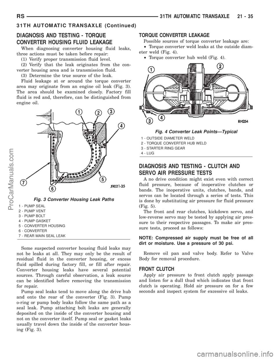
Fluid leakage at or around the torque converter
area may originate from an engine oil leak (Fig. 3).
The area should be examined closely. Factory fill
fluid is red and, therefore, can be distinguished from
engine oil.
Some suspected converter housing fluid leaks may
not be leaks at all. They may only be the result of
residual fluid in the converter housing, or excess
fluid spilled during factory fill, or fill after repair.
Converter housing leaks have several potential
sources. Through careful observation, a leak source
can be identified before removing the transmission
for repair.
Pump seal leaks tend to move along the drive hub
and onto the rear of the converter (Fig. 3). Pump
o-ring or pump body leaks follow the same path as a
seal leak. Pump attaching bolt leaks are generally
deposited on the inside of the converter housing and
not on the converter itself. Pump seal or gasket leaks
usually travel down the inside of the converter hous-
ing (Fig. 3).
TORQUE CONVERTER LEAKAGE
Possible sources of torque converter leakage are:
²Torque converter weld leaks at the outside diam-
eter weld (Fig. 4).
²Torque converter hub weld (Fig. 4).
DIAGNOSIS AND TESTING - CLUTCH AND
SERVO AIR PRESSURE TESTS
A no drive condition might exist even with correct
fluid pressure, because of inoperative clutches or
bands. The inoperative units, clutches, bands, and
servos can be located through a series of tests. This
is done by substituting air pressure for fluid pressure
(Fig. 5).
The front and rear clutches, kickdown servo, and
low-reverse servo may be tested by applying air pres-
sure to their respective passages. To make air pres-
sure tests, proceed as follows:
NOTE: Compressed air supply must be free of all
dirt or moisture. Use a pressure of 30 psi.
Remove oil pan and valve body. Refer to Valve
Body for removal procedure.
FRONT CLUTCH
Apply air pressure to front clutch apply passage
and listen for a dull thud which indicates that front
clutch is operating. Hold air pressure on for a few
seconds and inspect system for excessive oil leaks.
Fig. 3 Converter Housing Leak Paths
1 - PUMP SEAL
2 - PUMP VENT
3 - PUMP BOLT
4 - PUMP GASKET
5 - CONVERTER HOUSING
6 - CONVERTER
7 - REAR MAIN SEAL LEAK
Fig. 4 Converter Leak PointsÐTypical
1 - OUTSIDE DIAMETER WELD
2 - TORQUE CONVERTER HUB WELD
3 - STARTER RING GEAR
4 - LUG
RS31TH AUTOMATIC TRANSAXLE21-35
31TH AUTOMATIC TRANSAXLE (Continued)
ProCarManuals.com