2002 CHRYSLER CARAVAN automatic transmission
[x] Cancel search: automatic transmissionPage 1680 of 2399

IMPELLER
The impeller (Fig. 230) is an integral part of the
converter housing. The impeller consists of curved
blades placed radially along the inside of the housing
on the transmission side of the converter. As the con-
verter housing is rotated by the engine, so is the
impeller, because they are one and the same and are
the driving member of the system.
Fig. 230 Impeller
1 - ENGINE FLEXPLATE 4 - ENGINE ROTATION
2 - OIL FLOW FROM IMPELLER SECTION INTO TURBINE
SECTION5 - ENGINE ROTATION
3 - IMPELLER VANES AND COVER ARE INTEGRAL
RS31TH AUTOMATIC TRANSAXLE21 - 123
TORQUE CONVERTER (Continued)
ProCarManuals.com
Page 1683 of 2399
OPERATION
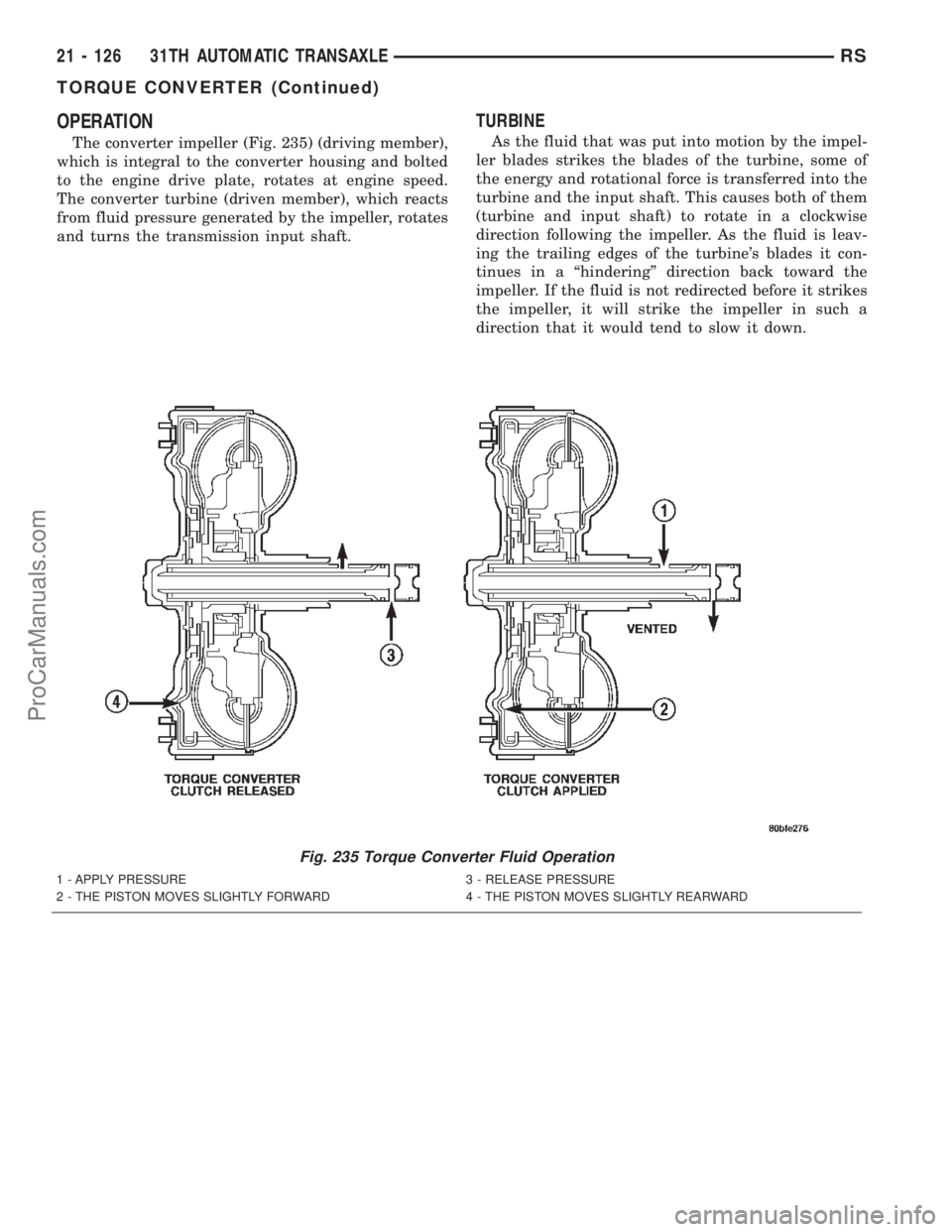
The converter impeller (Fig. 235) (driving member),
which is integral to the converter housing and bolted
to the engine drive plate, rotates at engine speed.
The converter turbine (driven member), which reacts
from fluid pressure generated by the impeller, rotates
and turns the transmission input shaft.
TURBINE
As the fluid that was put into motion by the impel-
ler blades strikes the blades of the turbine, some of
the energy and rotational force is transferred into the
turbine and the input shaft. This causes both of them
(turbine and input shaft) to rotate in a clockwise
direction following the impeller. As the fluid is leav-
ing the trailing edges of the turbine's blades it con-
tinues in a ªhinderingº direction back toward the
impeller. If the fluid is not redirected before it strikes
the impeller, it will strike the impeller in such a
direction that it would tend to slow it down.
Fig. 235 Torque Converter Fluid Operation
1 - APPLY PRESSURE 3 - RELEASE PRESSURE
2 - THE PISTON MOVES SLIGHTLY FORWARD 4 - THE PISTON MOVES SLIGHTLY REARWARD
21 - 126 31TH AUTOMATIC TRANSAXLERS
TORQUE CONVERTER (Continued)
ProCarManuals.com
Page 1684 of 2399
STATOR
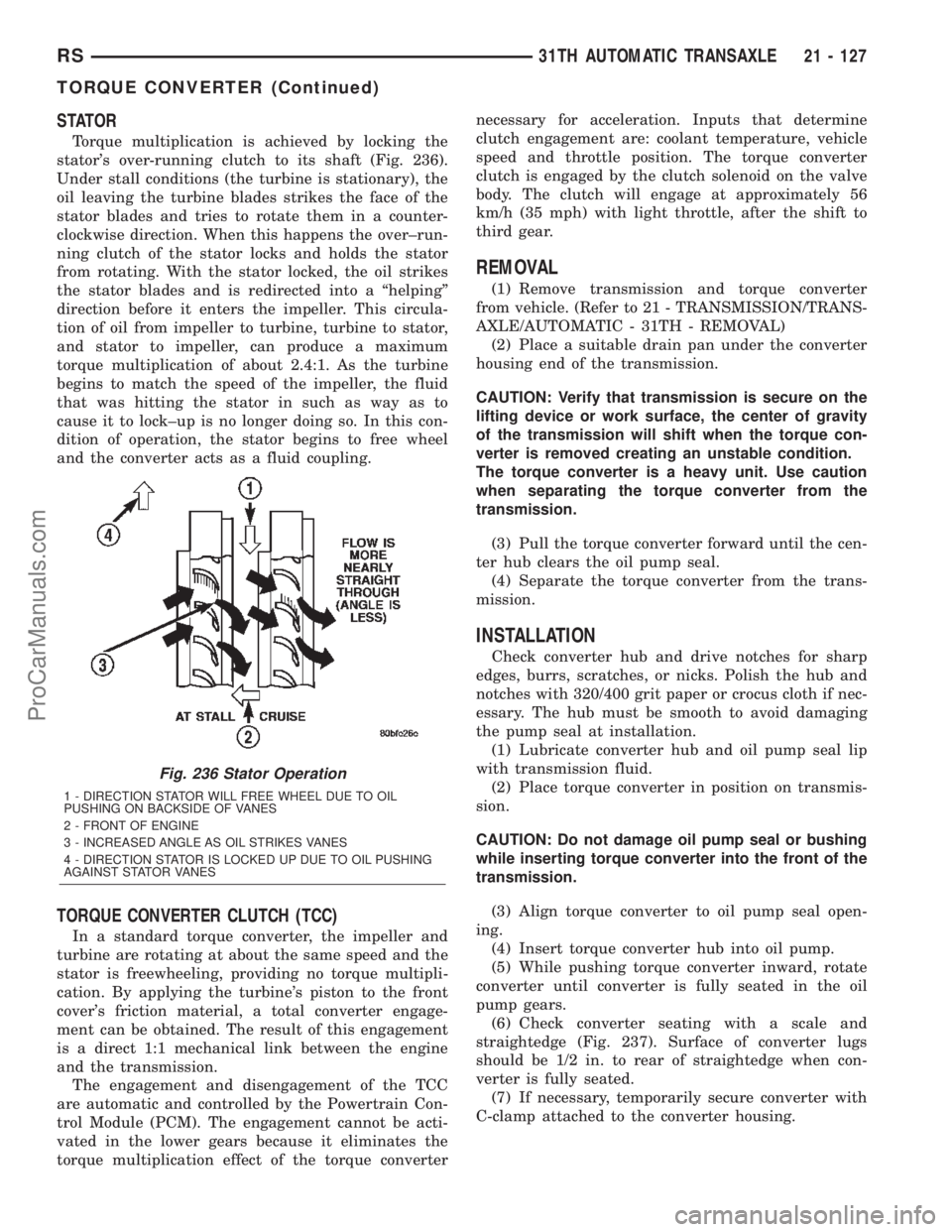
Torque multiplication is achieved by locking the
stator's over-running clutch to its shaft (Fig. 236).
Under stall conditions (the turbine is stationary), the
oil leaving the turbine blades strikes the face of the
stator blades and tries to rotate them in a counter-
clockwise direction. When this happens the over±run-
ning clutch of the stator locks and holds the stator
from rotating. With the stator locked, the oil strikes
the stator blades and is redirected into a ªhelpingº
direction before it enters the impeller. This circula-
tion of oil from impeller to turbine, turbine to stator,
and stator to impeller, can produce a maximum
torque multiplication of about 2.4:1. As the turbine
begins to match the speed of the impeller, the fluid
that was hitting the stator in such as way as to
cause it to lock±up is no longer doing so. In this con-
dition of operation, the stator begins to free wheel
and the converter acts as a fluid coupling.
TORQUE CONVERTER CLUTCH (TCC)
In a standard torque converter, the impeller and
turbine are rotating at about the same speed and the
stator is freewheeling, providing no torque multipli-
cation. By applying the turbine's piston to the front
cover's friction material, a total converter engage-
ment can be obtained. The result of this engagement
is a direct 1:1 mechanical link between the engine
and the transmission.
The engagement and disengagement of the TCC
are automatic and controlled by the Powertrain Con-
trol Module (PCM). The engagement cannot be acti-
vated in the lower gears because it eliminates the
torque multiplication effect of the torque converternecessary for acceleration. Inputs that determine
clutch engagement are: coolant temperature, vehicle
speed and throttle position. The torque converter
clutch is engaged by the clutch solenoid on the valve
body. The clutch will engage at approximately 56
km/h (35 mph) with light throttle, after the shift to
third gear.
REMOVAL
(1) Remove transmission and torque converter
from vehicle. (Refer to 21 - TRANSMISSION/TRANS-
AXLE/AUTOMATIC - 31TH - REMOVAL)
(2) Place a suitable drain pan under the converter
housing end of the transmission.
CAUTION: Verify that transmission is secure on the
lifting device or work surface, the center of gravity
of the transmission will shift when the torque con-
verter is removed creating an unstable condition.
The torque converter is a heavy unit. Use caution
when separating the torque converter from the
transmission.
(3) Pull the torque converter forward until the cen-
ter hub clears the oil pump seal.
(4) Separate the torque converter from the trans-
mission.
INSTALLATION
Check converter hub and drive notches for sharp
edges, burrs, scratches, or nicks. Polish the hub and
notches with 320/400 grit paper or crocus cloth if nec-
essary. The hub must be smooth to avoid damaging
the pump seal at installation.
(1) Lubricate converter hub and oil pump seal lip
with transmission fluid.
(2) Place torque converter in position on transmis-
sion.
CAUTION: Do not damage oil pump seal or bushing
while inserting torque converter into the front of the
transmission.
(3) Align torque converter to oil pump seal open-
ing.
(4) Insert torque converter hub into oil pump.
(5) While pushing torque converter inward, rotate
converter until converter is fully seated in the oil
pump gears.
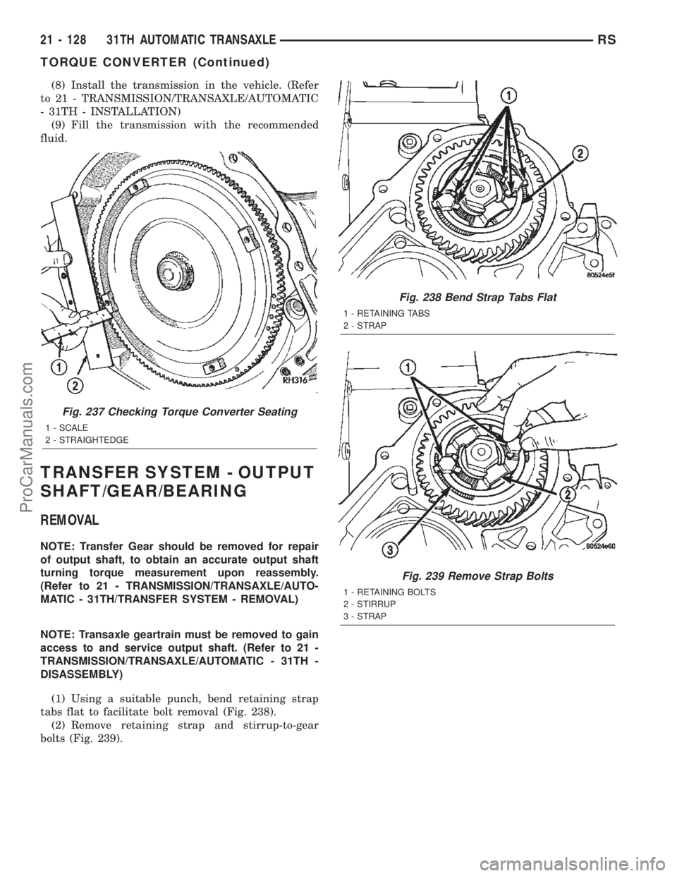
(6) Check converter seating with a scale and
straightedge (Fig. 237). Surface of converter lugs
should be 1/2 in. to rear of straightedge when con-
verter is fully seated.
(7) If necessary, temporarily secure converter with
C-clamp attached to the converter housing.
Fig. 236 Stator Operation
1 - DIRECTION STATOR WILL FREE WHEEL DUE TO OIL
PUSHING ON BACKSIDE OF VANES
2 - FRONT OF ENGINE
3 - INCREASED ANGLE AS OIL STRIKES VANES
4 - DIRECTION STATOR IS LOCKED UP DUE TO OIL PUSHING
AGAINST STATOR VANES
RS31TH AUTOMATIC TRANSAXLE21 - 127
TORQUE CONVERTER (Continued)
ProCarManuals.com
Page 1685 of 2399
(8) Install the transmission in the vehicle. (Refer
to 21 - TRANSMISSION/TRANSAXLE/AUTOMATIC
- 31TH - INSTALLATION)
(9) Fill the transmission with the recommended
fluid.
TRANSFER SYSTEM - OUTPUT
SHAFT/GEAR/BEARING
REMOVAL
NOTE: Transfer Gear should be removed for repair
of output shaft, to obtain an accurate output shaft
turning torque measurement upon reassembly.
(Refer to 21 - TRANSMISSION/TRANSAXLE/AUTO-
MATIC - 31TH/TRANSFER SYSTEM - REMOVAL)
NOTE: Transaxle geartrain must be removed to gain
access to and service output shaft. (Refer to 21 -
TRANSMISSION/TRANSAXLE/AUTOMATIC - 31TH -
DISASSEMBLY)
(1) Using a suitable punch, bend retaining strap
tabs flat to facilitate bolt removal (Fig. 238).
(2) Remove retaining strap and stirrup-to-gear
bolts (Fig. 239).
Fig. 237 Checking Torque Converter Seating
1 - SCALE
2 - STRAIGHTEDGE
Fig. 238 Bend Strap Tabs Flat
1 - RETAINING TABS
2 - STRAP
Fig. 239 Remove Strap Bolts
1 - RETAINING BOLTS
2 - STIRRUP
3 - STRAP
21 - 128 31TH AUTOMATIC TRANSAXLERS
TORQUE CONVERTER (Continued)
ProCarManuals.com
Page 1692 of 2399
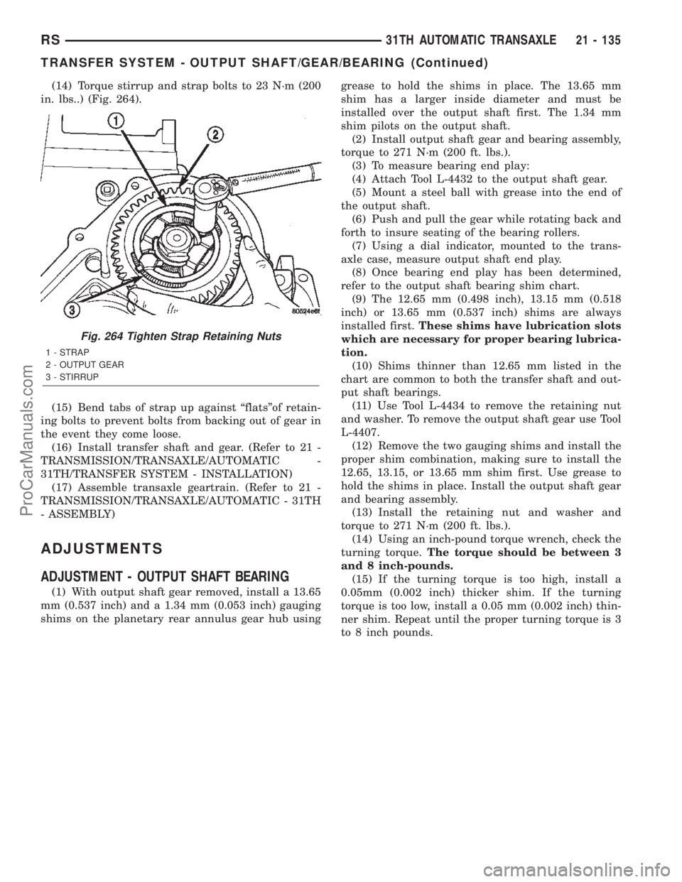
(14) Torque stirrup and strap bolts to 23 N´m (200
in. lbs..) (Fig. 264).
(15) Bend tabs of strap up against ªflatsºof retain-
ing bolts to prevent bolts from backing out of gear in
the event they come loose.
(16) Install transfer shaft and gear. (Refer to 21 -
TRANSMISSION/TRANSAXLE/AUTOMATIC -
31TH/TRANSFER SYSTEM - INSTALLATION)
(17) Assemble transaxle geartrain. (Refer to 21 -
TRANSMISSION/TRANSAXLE/AUTOMATIC - 31TH
- ASSEMBLY)
ADJUSTMENTS
ADJUSTMENT - OUTPUT SHAFT BEARING
(1) With output shaft gear removed, install a 13.65
mm (0.537 inch) and a 1.34 mm (0.053 inch) gauging
shims on the planetary rear annulus gear hub usinggrease to hold the shims in place. The 13.65 mm
shim has a larger inside diameter and must be
installed over the output shaft first. The 1.34 mm
shim pilots on the output shaft.
(2) Install output shaft gear and bearing assembly,
torque to 271 N´m (200 ft. lbs.).
(3) To measure bearing end play:
(4) Attach Tool L-4432 to the output shaft gear.
(5) Mount a steel ball with grease into the end of
the output shaft.
(6) Push and pull the gear while rotating back and
forth to insure seating of the bearing rollers.
(7) Using a dial indicator, mounted to the trans-
axle case, measure output shaft end play.
(8) Once bearing end play has been determined,
refer to the output shaft bearing shim chart.
(9) The 12.65 mm (0.498 inch), 13.15 mm (0.518
inch) or 13.65 mm (0.537 inch) shims are always
installed first.These shims have lubrication slots
which are necessary for proper bearing lubrica-
tion.
(10) Shims thinner than 12.65 mm listed in the
chart are common to both the transfer shaft and out-
put shaft bearings.
(11) Use Tool L-4434 to remove the retaining nut
and washer. To remove the output shaft gear use Tool
L-4407.
(12) Remove the two gauging shims and install the
proper shim combination, making sure to install the
12.65, 13.15, or 13.65 mm shim first. Use grease to
hold the shims in place. Install the output shaft gear
and bearing assembly.
(13) Install the retaining nut and washer and
torque to 271 N´m (200 ft. lbs.).
(14) Using an inch-pound torque wrench, check the
turning torque.The torque should be between 3
and 8 inch-pounds.
(15) If the turning torque is too high, install a
0.05mm (0.002 inch) thicker shim. If the turning
torque is too low, install a 0.05 mm (0.002 inch) thin-
ner shim. Repeat until the proper turning torque is 3
to 8 inch pounds.
Fig. 264 Tighten Strap Retaining Nuts
1 - STRAP
2 - OUTPUT GEAR
3 - STIRRUP
RS31TH AUTOMATIC TRANSAXLE21 - 135
TRANSFER SYSTEM - OUTPUT SHAFT/GEAR/BEARING (Continued)
ProCarManuals.com
Page 1700 of 2399
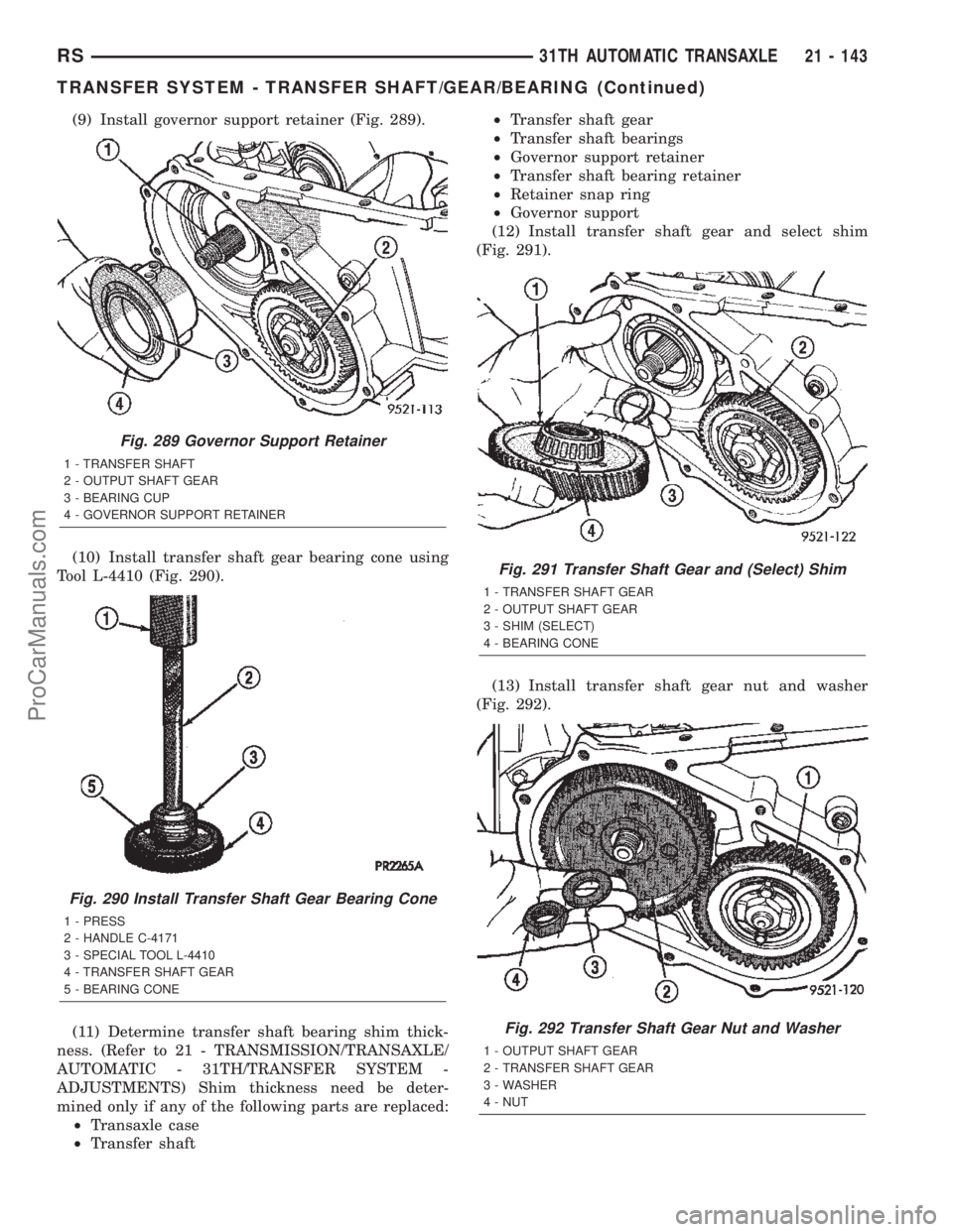
(9) Install governor support retainer (Fig. 289).
(10) Install transfer shaft gear bearing cone using
Tool L-4410 (Fig. 290).
(11) Determine transfer shaft bearing shim thick-
ness. (Refer to 21 - TRANSMISSION/TRANSAXLE/
AUTOMATIC - 31TH/TRANSFER SYSTEM -
ADJUSTMENTS) Shim thickness need be deter-
mined only if any of the following parts are replaced:
²Transaxle case
²Transfer shaft²Transfer shaft gear
²Transfer shaft bearings
²Governor support retainer
²Transfer shaft bearing retainer
²Retainer snap ring
²Governor support
(12) Install transfer shaft gear and select shim
(Fig. 291).
(13) Install transfer shaft gear nut and washer
(Fig. 292).
Fig. 289 Governor Support Retainer
1 - TRANSFER SHAFT
2 - OUTPUT SHAFT GEAR
3 - BEARING CUP
4 - GOVERNOR SUPPORT RETAINER
Fig. 290 Install Transfer Shaft Gear Bearing Cone
1 - PRESS
2 - HANDLE C-4171
3 - SPECIAL TOOL L-4410
4 - TRANSFER SHAFT GEAR
5 - BEARING CONE
Fig. 291 Transfer Shaft Gear and (Select) Shim
1 - TRANSFER SHAFT GEAR
2 - OUTPUT SHAFT GEAR
3 - SHIM (SELECT)
4 - BEARING CONE
Fig. 292 Transfer Shaft Gear Nut and Washer
1 - OUTPUT SHAFT GEAR
2 - TRANSFER SHAFT GEAR
3 - WASHER
4 - NUT
RS31TH AUTOMATIC TRANSAXLE21 - 143
TRANSFER SYSTEM - TRANSFER SHAFT/GEAR/BEARING (Continued)
ProCarManuals.com
Page 1718 of 2399
41TE AUTOMATIC TRANSAXLE
TABLE OF CONTENTS
page page
41TE AUTOMATIC TRANSAXLE
DESCRIPTION........................162
OPERATION..........................164
DIAGNOSIS AND TESTING
DIAGNOSIS AND TESTING - 41TE
TRANSAXLE GENERAL DIAGNOSIS......164
DIAGNOSIS AND TESTING - ROAD TEST . . 165
DIAGNOSIS AND TESTING - HYDRAULIC
PRESSURE TESTS...................165
DIAGNOSIS AND TESTING - CLUTCH AIR
PRESSURE TESTS...................168
DIAGNOSIS AND TESTING - TORQUE
CONVERTER HOUSING FLUID LEAKAGE . . 168
REMOVAL............................169
DISASSEMBLY........................171
ASSEMBLY...........................190
INSTALLATION........................213
SCHEMATICS AND DIAGRAMS
41TE TRANSAXLE HYDRAULIC
SCHEMATICS.......................216
SPECIFICATIONS - 41TE TRANSAXLE......228
SPECIAL TOOLS
41TE AUTOMATIC TRANSAXLE.........230
ACCUMULATOR
DESCRIPTION........................236
OPERATION..........................236
AUTOSTICK SWITCH
DESCRIPTION........................237
OPERATION..........................237
DRIVING CLUTCHES
DESCRIPTION........................237
OPERATION..........................238
FINAL DRIVE
DISASSEMBLY........................238
ASSEMBLY...........................243
ADJUSTMENTS
ADJUSTMENT - DIFFERENTIAL BEARING
PRELOAD..........................246
FLUID
STANDARD PROCEDURE
FLUID LEVEL AND CONDITION CHECK . . . 249
STANDARD PROCEDURE - FLUID AND
FILTER SERVICE.....................250
GEAR SHIFT CABLE
REMOVAL............................251
INSTALLATION........................253
ADJUSTMENTS
GEARSHIFT CABLE ADJUSTMENT.......254
HOLDING CLUTCHES
DESCRIPTION........................255OPERATION..........................255
INPUT CLUTCH ASSEMBLY
DISASSEMBLY........................255
ASSEMBLY...........................263
OIL PUMP
DESCRIPTION........................272
OPERATION..........................272
STANDARD PROCEDURE - OIL PUMP
VOLUME CHECK.....................272
DISASSEMBLY........................273
ASSEMBLY...........................274
PLANETARY GEARTRAIN
DESCRIPTION........................274
OPERATION..........................274
SEAL - OIL PUMP
REMOVAL............................275
INSTALLATION........................275
SHIFT INTERLOCK SOLENOID
DESCRIPTION........................275
OPERATION..........................276
DIAGNOSIS AND TESTING - BRAKE/
TRANSMISSION SHIFT INTERLOCK
SOLENOID..........................277
REMOVAL............................277
INSTALLATION........................278
SOLENOID/PRESSURE SWITCH ASSY
DESCRIPTION........................279
OPERATION..........................280
REMOVAL............................280
INSTALLATION........................281
SPEED SENSOR - INPUT
DESCRIPTION........................281
OPERATION..........................282
REMOVAL............................282
INSTALLATION........................283
SPEED SENSOR - OUTPUT
DESCRIPTION........................283
OPERATION..........................283
REMOVAL............................284
INSTALLATION........................284
TORQUE CONVERTER
DESCRIPTION........................285
OPERATION..........................289
REMOVAL............................290
INSTALLATION........................290
TRANSMISSION CONTROL RELAY
DESCRIPTION........................291
OPERATION..........................291
TRANSMISSION RANGE SENSOR
DESCRIPTION........................291
RS41TE AUTOMATIC TRANSAXLE21 - 161
ProCarManuals.com
Page 1719 of 2399
OPERATION..........................292
REMOVAL............................292
INSTALLATION........................292
TRD LINK
DESCRIPTION........................292
OPERATION..........................292
VALVE BODY
DESCRIPTION........................293OPERATION..........................293
REMOVAL
REMOVAL..........................294
REMOVAL..........................296
DISASSEMBLY........................297
ASSEMBLY...........................301
INSTALLATION........................306
41TE AUTOMATIC
TRANSAXLE
DESCRIPTION
The 41TE (Fig. 1) is a four-speed transaxle that is
a conventional hydraulic/mechanical assembly with
an integral differential, and is controlled with adap-
tive electronic controls and monitors. The hydraulic
system of the transaxle consists of the transaxle
fluid, fluid passages, hydraulic valves, and various
line pressure control components. An input clutch
assembly which houses the underdrive, overdrive,
and reverse clutches is used. It also utilizes separate
holding clutches: 2nd/4th gear and Low/Reverse. The
primary mechanical components of the transaxle con-
sist of the following:
²Three multiple disc input clutches
²Two multiple disc holding clutches
²Four hydraulic accumulators
²Two planetary gear sets
²Hydraulic oil pump²Valve body
²Solenoid/Pressure switch assembly
²Integral differential assembly
Control of the transaxle is accomplished by fully
adaptive electronics. Optimum shift scheduling is
accomplished through continuous real-time sensor
feedback information provided to the Transmission
Control Module (TCM).
The TCM is the heart of the electronic control sys-
tem and relies on information from various direct
and indirect inputs (sensors, switches, etc.) to deter-
mine driver demand and vehicle operating condi-
tions. With this information, the TCM can calculate
and perform timely and quality shifts through vari-
ous output or control devices (solenoid pack, trans-
mission control relay, etc.).
The TCM also performs certain self-diagnostic
functions and provides comprehensive information
(sensor data, DTC's, etc.) which is helpful in proper
diagnosis and repair. This information can be viewed
with the DRB scan tool.
21 - 162 41TE AUTOMATIC TRANSAXLERS
ProCarManuals.com