2002 CHRYSLER CARAVAN auxiliary battery
[x] Cancel search: auxiliary batteryPage 359 of 2399

(M) Check Engine Lamp (MIL) will illuminate during engine operation if this Diagnostic Trouble Code was recorded.
(G) Generator Lamp Illuminated
GENERIC
SCAN TOOL
CODEDRB SCAN TOOL DISPLAY DESCRIPTION OF DIAGNOSTIC TROUBLE CODE
P1298 Lean Operation at Wide Open Throttle A prolonged lean condition is detected during Wide Open
Throttle.
P1299 (M) Vacuum Leak Found (IAC Fully
Seated)MAP Sensor signal does not correlate to Throttle Position
Sensor signal. Possible vacuum leak.
P1388 Auto Shutdown Relay Control Circuit An open or shorted condition detected in the ASD or CNG
shutoff relay control ckt.
P1389 No ASD Relay Output Voltage At PCM No Z1 or Z2 voltage sensed when the auto shutdown relay is
energized.
P1390 (M) Timing Belt Skipped 1 Tooth or More Relationship between Cam and Crank signals not correct.
P1391 (M) Intermittent Loss of CMP or CKP Loss of the Cam Position Sensor or Crank Position sensor
has occurred. For PL 2.0L
P1398 (M) Mis-Fire Adaptive Numerator at Limit PCM is unable to learn the Crank Sensor's signal in
preparation for Misfire Diagnostics. Probable defective Crank
Sensor.
P1399 Wait To Start Lamp Circuit An open or shorted condition detected in the Wait to Start
Lamp circuit.
P1403 No 5 Volts to EGR Sensor Loss of 5v feed to the EGR position sensor.
P1476 Too Little Secondary Air Insufficient flow of secondary air injection detected during
aspirator test.(was P0411)
P1477 Too Much Secondary Air Excessive flow of secondary air injection detected during
aspirator test (was P0411).
P1478 (M) Battery Temp Sensor Volts Out of Limit Internal temperature sensor input voltage out of an
acceptable range.
P1479 Transmission Fan Relay Circuit An open or shorted condition detected in the transmission
fan relay circuit.
P1480 PCV Solenoid Circuit An open or shorted condition detected in the PCV solenoid
circuit.
P1481 EATX RPM Pulse Performance ETAX RPM pulse generator signal for misfire detection does
not correlate with expected value.
P1482 Catalyst Temperature Sensor Circuit
Shorted LowCatalyst temperature sensor circuit shorted low.
P1483 Catalyst Temperature Sensor Circuit
Shorted High.Catalyst temperature sensor circuit shorted high.
P1484 Catalytic Converter Overheat Detected A catalyst overheat condition has been detected by the
catalyst temperature sensor.
P1485 Air Injection Solenoid Circuit An open or shorted condition detected in the air assist
solenoid circuit.
P1486 (M) Evap Leak Monitor Pinched Hose
FoundLDP has detected a pinched hose in the evaporative hose
system.
P1487 Hi Speed Rad Fan CTRL Relay Circuit An open or shorted condition detected in the control circuit of
the #2 high speed radiator fan control relay.
P1488 Auxiliary 5 Volt Supply Output Too Low Auxiliary 5 volt sensor feed is sensed to be below an
acceptable limit.
8E - 22 ELECTRONIC CONTROL MODULESRS
POWERTRAIN CONTROL MODULE (Continued)
ProCarManuals.com
Page 1465 of 2399
(3) Push the quick-connect fitting over the fuel
tube until theretainer seats and a click is heard.
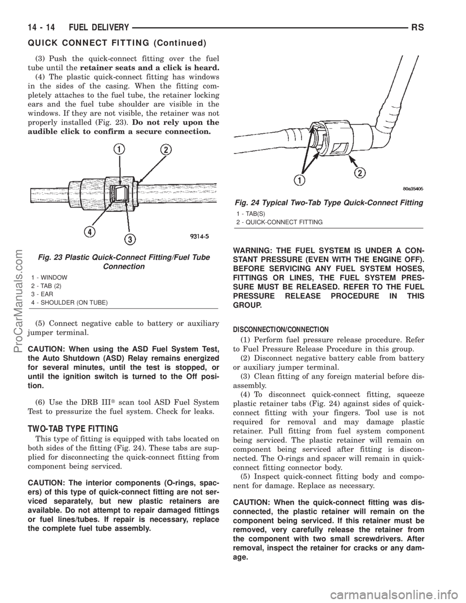
(4) The plastic quick-connect fitting has windows
in the sides of the casing. When the fitting com-
pletely attaches to the fuel tube, the retainer locking
ears and the fuel tube shoulder are visible in the
windows. If they are not visible, the retainer was not
properly installed (Fig. 23).Do not rely upon the
audible click to confirm a secure connection.
(5) Connect negative cable to battery or auxiliary
jumper terminal.
CAUTION: When using the ASD Fuel System Test,
the Auto Shutdown (ASD) Relay remains energized
for several minutes, until the test is stopped, or
until the ignition switch is turned to the Off posi-
tion.
(6) Use the DRB IIItscan tool ASD Fuel System
Test to pressurize the fuel system. Check for leaks.
TWO-TAB TYPE FITTING
This type of fitting is equipped with tabs located on
both sides of the fitting (Fig. 24). These tabs are sup-
plied for disconnecting the quick-connect fitting from
component being serviced.
CAUTION: The interior components (O-rings, spac-
ers) of this type of quick-connect fitting are not ser-
viced separately, but new plastic retainers are
available. Do not attempt to repair damaged fittings
or fuel lines/tubes. If repair is necessary, replace
the complete fuel tube assembly.WARNING: THE FUEL SYSTEM IS UNDER A CON-
STANT PRESSURE (EVEN WITH THE ENGINE OFF).
BEFORE SERVICING ANY FUEL SYSTEM HOSES,
FITTINGS OR LINES, THE FUEL SYSTEM PRES-
SURE MUST BE RELEASED. REFER TO THE FUEL
PRESSURE RELEASE PROCEDURE IN THIS
GROUP.
DISCONNECTION/CONNECTION
(1) Perform fuel pressure release procedure. Refer
to Fuel Pressure Release Procedure in this group.
(2) Disconnect negative battery cable from battery
or auxiliary jumper terminal.
(3) Clean fitting of any foreign material before dis-
assembly.
(4) To disconnect quick-connect fitting, squeeze
plastic retainer tabs (Fig. 24) against sides of quick-
connect fitting with your fingers. Tool use is not
required for removal and may damage plastic
retainer. Pull fitting from fuel system component
being serviced. The plastic retainer will remain on
component being serviced after fitting is discon-
nected. The O-rings and spacer will remain in quick-
connect fitting connector body.
(5) Inspect quick-connect fitting body and compo-
nent for damage. Replace as necessary.
CAUTION: When the quick-connect fitting was dis-
connected, the plastic retainer will remain on the
component being serviced. If this retainer must be
removed, very carefully release the retainer from
the component with two small screwdrivers. After
removal, inspect the retainer for cracks or any dam-
age.
Fig. 23 Plastic Quick-Connect Fitting/Fuel Tube
Connection
1 - WINDOW
2-TAB(2)
3 - EAR
4 - SHOULDER (ON TUBE)
Fig. 24 Typical Two-Tab Type Quick-Connect Fitting
1 - TAB(S)
2 - QUICK-CONNECT FITTING
14 - 14 FUEL DELIVERYRS
QUICK CONNECT FITTING (Continued)
ProCarManuals.com
Page 1466 of 2399
(6) Prior to connecting quick-connect fitting to
component being serviced, check condition of fitting
and component. Clean parts with a lint-free cloth.
Lubricate with clean engine oil.
(7) Insert quick-connect fitting to component being
serviced and into plastic retainer. When a connection
is made, a click will be heard.
(8) Verify a locked condition by firmly pulling on
fuel tube and fitting (15-30 lbs.).
(9) Connect negative cable to battery or auxiliary
jumper terminal.
(10) Use the DRB IIItscan tool ASD Fuel System
Test to pressurize the fuel system. Check for leaks.
PLASTIC RETAINER RING TYPE FITTING
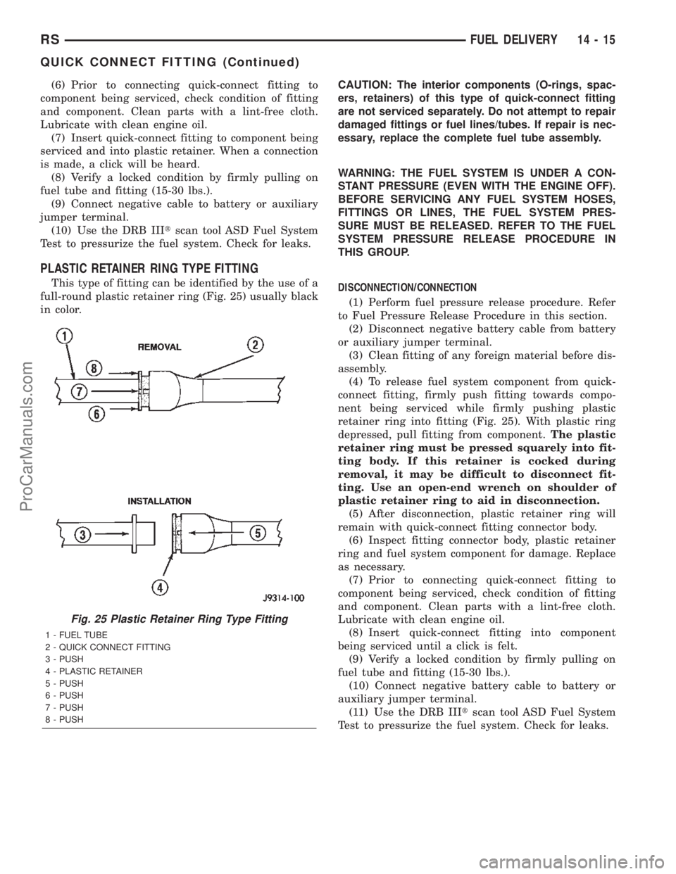
This type of fitting can be identified by the use of a
full-round plastic retainer ring (Fig. 25) usually black
in color.CAUTION: The interior components (O-rings, spac-
ers, retainers) of this type of quick-connect fitting
are not serviced separately. Do not attempt to repair
damaged fittings or fuel lines/tubes. If repair is nec-
essary, replace the complete fuel tube assembly.
WARNING: THE FUEL SYSTEM IS UNDER A CON-
STANT PRESSURE (EVEN WITH THE ENGINE OFF).
BEFORE SERVICING ANY FUEL SYSTEM HOSES,
FITTINGS OR LINES, THE FUEL SYSTEM PRES-
SURE MUST BE RELEASED. REFER TO THE FUEL
SYSTEM PRESSURE RELEASE PROCEDURE IN
THIS GROUP.
DISCONNECTION/CONNECTION
(1) Perform fuel pressure release procedure. Refer
to Fuel Pressure Release Procedure in this section.
(2) Disconnect negative battery cable from battery
or auxiliary jumper terminal.
(3) Clean fitting of any foreign material before dis-
assembly.
(4) To release fuel system component from quick-
connect fitting, firmly push fitting towards compo-
nent being serviced while firmly pushing plastic
retainer ring into fitting (Fig. 25). With plastic ring
depressed, pull fitting from component.The plastic
retainer ring must be pressed squarely into fit-
ting body. If this retainer is cocked during
removal, it may be difficult to disconnect fit-
ting. Use an open-end wrench on shoulder of
plastic retainer ring to aid in disconnection.
(5) After disconnection, plastic retainer ring will
remain with quick-connect fitting connector body.
(6) Inspect fitting connector body, plastic retainer
ring and fuel system component for damage. Replace
as necessary.
(7) Prior to connecting quick-connect fitting to
component being serviced, check condition of fitting
and component. Clean parts with a lint-free cloth.
Lubricate with clean engine oil.
(8) Insert quick-connect fitting into component
being serviced until a click is felt.
(9) Verify a locked condition by firmly pulling on
fuel tube and fitting (15-30 lbs.).
(10) Connect negative battery cable to battery or
auxiliary jumper terminal.
(11) Use the DRB IIItscan tool ASD Fuel System
Test to pressurize the fuel system. Check for leaks.
Fig. 25 Plastic Retainer Ring Type Fitting
1 - FUEL TUBE
2 - QUICK CONNECT FITTING
3 - PUSH
4 - PLASTIC RETAINER
5 - PUSH
6 - PUSH
7 - PUSH
8 - PUSH
RSFUEL DELIVERY14-15
QUICK CONNECT FITTING (Continued)
ProCarManuals.com
Page 2048 of 2399
INSTALLATION
(1) Install the glove box latch striker.
(2) Install the screws holding latch striker to
instrument panel.
(3) Close glove box door.
INSTRUMENT PANEL
ASSEMBLY
REMOVAL
(1) Disconnect and isolate the battery negative
cable.
(2) Remove the lower console:
(a) Remove six retaining screws.
(b) Pull rearward and disconnect the auxiliary
power outlet.
(c) Remove lower console from vehicle.
(3) Remove the bolts attaching the lower supports
to the instrument panel frame (Fig. 3).
(4) Remove the bolts attaching the lower supports
to the floor pan.
(5) Disconnect the wire connectors from the Pas-
senger Airbag.
(6) Remove the two screws to each right and left
cowl trim covers.
(7) Remove the both left and right side A-pillar
trim covers using a trim stick (special tool #C-4755)
or equivalent gently pry out on the trim covers and
remove.
(8) Remove the glove box:
(a) Push in on sides of glove box bin and lower
door.
(b) Pivot glove box downward and disengage
hinge hooks from instrument panel.
(c) Remove glove box from vehicle.
(9) Disconnect the antenna lead connector from
behind the glove box.
(10) Remove the four screws to the lower steering
column cover.
(11) Remove the eight screws to the steering col-
umn backing plate.
(12) Unclip the Data Link Connector (DLC) from
the steering column backing plate.
(13) Remove two screws to the left side instrument
panel silencer and remove (Fig. 4).
(14) Disconnect the left side wiring:
(a) Brake switch.
(b) Main bulkhead connector.
(c) Five harness connectors.
(d) Driver airbag connector.
(15) Remove the two screws to the hood release
handle.
(16) Remove five screws to steering column back-
ing plate and remove (Refer to 23 - BODY/INSTRU-
MENT PANEL/KNEE BLOCKER - REMOVAL).(17) Remove the two steering column shroud
retaining screws. Separate the shrouds and remove
from vehicle.
(18) Remove the screws attaching the instrument
panel reinforcement and remove (Fig. 5).
(19) Disconnect the steering column wiring. There
are seven connectors and then unclip the harness
from the column.
(20) Disconnect the Occupant Restraint Controller
(ORC) harness connector.
(21) Remove the four nuts retaining the steering
column to the dash panel steering column mounting
bracket and lower column to the floor (Fig. 6).
(22) Remove the four nuts attaching the instru-
ment panel to the brake pedal support bracket.
(23) Loosen the left side roll down bolt (Fig. 7).
(24) Remove the left side A-pillar retaining bolts.
There are two 13 mm bolts and one 10 mm bolt.
(25) If equipped with a mechanical transmission
range indicator:
(a) Remove the indicator cable loop.
(b) Remove the clip holding gear shift cable end
to the gear selector adapter.
(c) Pull the cable end from gear selector.
(d) Disconnect the clip for the indicator cable
and guide tube from the shift cable bracket and
move out of the way.
(26) Remove the instrument panel top cover. Using
a trim stick or equivalent, gently pry up on the front
edge of the top cover, pull rearward and remove from
vehicle.
(27) Disconnect the right side wire connectors from
the HVAC behind the glove box area and the two
antenna connectors behind the glove box hinge.
(28) Remove the right end cover by pulling out-
board.
(29) Remove the right side A-pillar retaining bolts.
There are two 13 mm bolts and one 10 mm bolt.
(30) Loosen the right side roll down bolt.
(31) Disconnect the two front window defroster
grid wire connectors. One on each side of vehicle.
(32) Remove both the left and right power mirrors:
(a) Using a trim stick or equivalent, gently pry
out on mirror trim cover.
(b) Open door and remove the three torx retain-
ing screws.
(c) Disconnect the wire connector and remove
mirror from the vehicle.
(33) Feed power mirror wire harness inboard
through the A-pillar.
(34) Remove the bolts attaching the instrument
panel frame to the dash panel below windshield
opening.
(35) With the help of an assistant remove the
instrument panel from vehicle. Lift the instrument
RSINSTRUMENT PANEL23-65
GLOVE BOX LATCH STRIKER (Continued)
ProCarManuals.com
Page 2051 of 2399
(17) Install the screws attaching the instrument
panel reinforcement (Fig. 5).
(18) Connect the shrouds and install the two steer-
ing column shroud retaining screws.
(19) Install five screws to the left under column
instrument panel reinforcement brace.
(20) Install the two screws to the hood release
handle.
(21) Connect the left side wiring:
(a) Brake switch.
(b) Main bulkhead connector.
(c) Five harness connectors.
(d) Driver airbag connector.
(22) Install two screws to the left side instrument
panel silencer (Fig. 4).
(23) Clip the Data Link Connector (DLC) to the
steering column backing plate.
(24) Install the eight screws to the steering column
backing plate.
(25) Install the four screws to the lower steering
column cover.
(26) Install the glove box:
(a) Install glove box into the vehicle. Line up the
hinges and firmly snap together.
(b) Push in on sides of glove box bin and raise
door.
(27) Install the both left and right side A-pillar
trim covers. Position trim cover over slots and firmly
snap into place.
(28) Install the two screws to each right and left
cowl trim covers.
(29) Connect the wire connectors to the Passenger
Airbag.
(30) Install the bolts attaching the lower supports
to the floor pan.
(31) Install the bolts attaching the lower supports
to the instrument panel frame (Fig. 3).
(32) Install the lower console:
(a) Install lower console to vehicle.
(b) Connect the auxiliary power outlet.
(c) Install the six retaining screws.
(33) Connect the battery negative cable.
INSTRUMENT PANEL CENTER
BEZEL
REMOVAL
(1) Disconnect and isolate the battery negative
cable.
(2) Insert the trim stick (special tool #C-4755) or
equivalent between access cover and center bezel
gently pry outward.
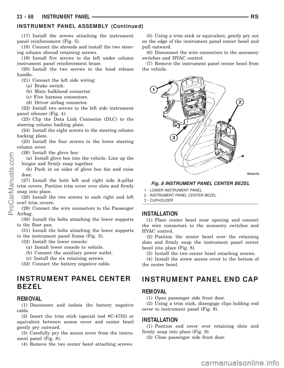
(3) Carefully pry the access cover from the instru-
ment panel (Fig. 8).
(4) Remove the two center bezel attaching screws.(5) Using a trim stick or equivalent, gently pry out
on the edge of the instrument panel center bezel and
pull outward.
(6) Disconnect the wire connectors to the accessory
switches and HVAC control.
(7) Remove the instrument panel center bezel from
the vehicle.
INSTALLATION
(1) Place center bezel near opening and connect
the wire connectors to the accessory switches and
HVAC control.
(2) Position the center bezel over the retaining
slots and firmly snap the instrument panel center
bezel into place (Fig. 8).
(3) Install the two center bezel attaching screws.
(4) Install the screw access cover to the bottom of
the center bezel.
INSTRUMENT PANEL END CAP
REMOVAL
(1) Open passenger side front door.
(2) Using a trim stick, disengage clips holding end
cover to instrument panel (Fig. 9).
INSTALLATION
(1) Position end cover over retaining slots and
firmly snap into place (Fig. 9).
(2) Close passenger side front door.
Fig. 8 INSTRUMENT PANEL CENTER BEZEL
1 - LOWER INSTRUMENT PANEL
2 - INSTRUMENT PANEL CENTER BEZEL
3 - CUPHOLDER
23 - 68 INSTRUMENT PANELRS
INSTRUMENT PANEL ASSEMBLY (Continued)
ProCarManuals.com
Page 2300 of 2399
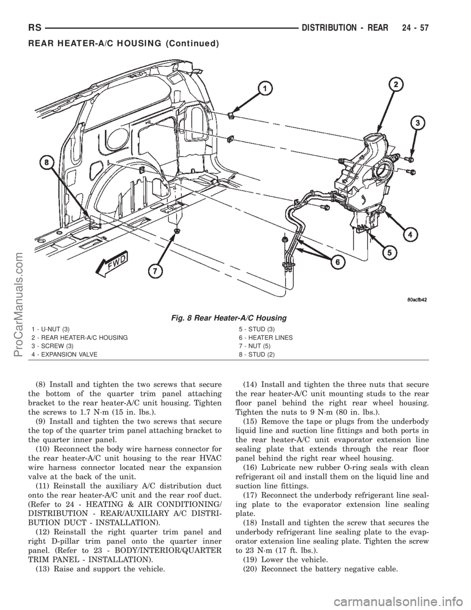
(8) Install and tighten the two screws that secure
the bottom of the quarter trim panel attaching
bracket to the rear heater-A/C unit housing. Tighten
the screws to 1.7 N´m (15 in. lbs.).
(9) Install and tighten the two screws that secure
the top of the quarter trim panel attaching bracket to
the quarter inner panel.
(10) Reconnect the body wire harness connector for
the rear heater-A/C unit housing to the rear HVAC
wire harness connector located near the expansion
valve at the back of the unit.
(11) Reinstall the auxiliary A/C distribution duct
onto the rear heater-A/C unit and the rear roof duct.
(Refer to 24 - HEATING & AIR CONDITIONING/
DISTRIBUTION - REAR/AUXILIARY A/C DISTRI-
BUTION DUCT - INSTALLATION).
(12) Reinstall the right quarter trim panel and
right D-pillar trim panel onto the quarter inner
panel. (Refer to 23 - BODY/INTERIOR/QUARTER
TRIM PANEL - INSTALLATION).
(13) Raise and support the vehicle.(14) Install and tighten the three nuts that secure
the rear heater-A/C unit mounting studs to the rear
floor panel behind the right rear wheel housing.
Tighten the nuts to 9 N´m (80 in. lbs.).
(15) Remove the tape or plugs from the underbody
liquid line and suction line fittings and both ports in
the rear heater-A/C unit evaporator extension line
sealing plate that extends through the rear floor
panel behind the right rear wheel housing.
(16) Lubricate new rubber O-ring seals with clean
refrigerant oil and install them on the liquid line and
suction line fittings.
(17) Reconnect the underbody refrigerant line seal-
ing plate to the evaporator extension line sealing
plate.
(18) Install and tighten the screw that secures the
underbody refrigerant line sealing plate to the evap-
orator extension line sealing plate. Tighten the screw
to 23 N´m (17 ft. lbs.).
(19) Lower the vehicle.
(20) Reconnect the battery negative cable.
Fig. 8 Rear Heater-A/C Housing
1 - U-NUT (3)
2 - REAR HEATER-A/C HOUSING
3 - SCREW (3)
4 - EXPANSION VALVE5 - STUD (3)
6 - HEATER LINES
7 - NUT (5)
8 - STUD (2)
RSDISTRIBUTION - REAR24-57
REAR HEATER-A/C HOUSING (Continued)
ProCarManuals.com