Page 65 of 116

PERIODIC MAINTENANCE AND MINOR REPAIR
6-14
6 7. Remove the coolant drain bolt to
drain the cooling system.8. Loosen the radiator hose clamp
screw located at the left side of the
engine, and then pull off the hose
to drain the radiator.
9. After the coolant is completely
drained, thoroughly flush the cool-
ing system with clean tap water.
10. Install the coolant drain bolt, and
then tighten it to the specified
torque.
NOTE:@ Check the washer for damage and re-
place it if necessary. @
11. Connect the radiator hose, and
then tighten the clamp screw.
12. Pour the specified amount of rec-
ommended coolant into the radia-
tor and reservoir.
1. Coolant drain bolt
1. Screw clamp
Tightening torque:
Coolant drain bolt:
7 Nm (0.7 m·kg)
Antifreeze/water mixture ratio:
1:1
Recommended antifreeze:
High-quality ethylene glycol
antifreeze containing corrosion
inhibitors for aluminum engines
Coolant quantity:
Total amount:
2.55 L
Coolant reservoir capacity:
0.45 L
E_5jj.book Page 14 Friday, September 8, 2000 3:33 PM
Page 66 of 116

PERIODIC MAINTENANCE AND MINOR REPAIR
6-15
6
EC000080
CAUTION:@ l
If coolant is not available, use
distilled water or soft tap water
instead. Do not use hard water
or salt water since it is harmful
to the engine.
l
If water has been used instead
of coolant, replace it with cool-
ant as soon as possible, other-
wise the engine may not be
sufficiently cooled and the cool-
ing system will not be protected
against frost and corrosion.
l
If water has been added to the
coolant, have a Yamaha dealer
check the antifreeze content of
the coolant as soon as possible,
otherwise the effectiveness of
the coolant will be reduced.
@13. Install the radiator cap, start the
engine, let it idle for several min-
utes, and then turn it off.14. Remove the radiator cap to check
the coolant level in the radiator. If
necessary, add sufficient coolant
until it reaches the top of the radia-
tor, and then install the radiator
cap.
15. Check the coolant level in the res-
ervoir. If necessary, remove the
coolant reservoir cap, add coolant
to the maximum level mark, and
then install the cap.
16. Start the engine, and then check
the vehicle for coolant leakage. If
coolant is leaking, have a Yamaha
dealer check the cooling system.
17. Install the cowlings and the panel.
EAU03162
Cleaning the air filter element The air filter element should be cleaned
at the intervals specified in the periodic
maintenance and lubrication chart.
Clean the air filter element more fre-
quently if you are riding in unusually
wet or dusty areas.
1. Remove the rider seat. (See page
3-14 for rider seat removal and in-
stallation procedures.)
2. Remove the bolt at the front of the
fuel tank and loosen the bolt at the
rear.1. Bolt (front)
2. Bolt (rear)
E_5jj.book Page 15 Friday, September 8, 2000 3:33 PM
Page 67 of 116
PERIODIC MAINTENANCE AND MINOR REPAIR
6-16
6 3. Lift the front of the fuel tank, and
then tilt it back and away from the
air filter case. (Do not disconnect
the fuel hoses!)
EW000071
WARNING
@ l
Make sure that the fuel tank is
well supported.
l
Do not tilt or pull the fuel tank
too much, otherwise the fuel
hoses may come loose, which
could cause fuel leakage.
@4. Remove the air filter case cover by
removing the screws and bolt.5. Pull the air filter element out.
6. Lightly tap the air filter element to
remove most of the dust and dirt,
and then blow the remaining dirt
out with compressed air as shown.
If the air filter element is damaged,
replace it.
7. Insert the air filter element into the
air filter case.1. Bolt
2. Screw (´ 8)
3. Air filter case cover
1. Air filter element
E_5jj.book Page 16 Friday, September 8, 2000 3:33 PM
Page 68 of 116

PERIODIC MAINTENANCE AND MINOR REPAIR
6-17
6
EC000082
CAUTION:@ l
Make sure that the air filter ele-
ment is properly seated in the
air filter case.
l
The engine should never be op-
erated without the air filter ele-
ment installed, otherwise the
piston(s) and/or cylinder(s) may
become excessively worn.
@8. Install the air filter case cover by
installing the screws and bolt.
9. Place the fuel tank in the original
position, and then install the bolt at
the front and tighten the bolt at the
rear.
EW000072
WARNING
@ l
Before installing the fuel tank,
make sure that the fuel hoses
are not damaged. If any fuel
hose is damaged, do not start
the engine but have a Yamaha
dealer replace the hose, other-
wise fuel may leak.
l
Make sure that the fuel hoses
are properly connected and
routed, and not pinched.
@
EAU00630
Adjusting the carburetors The carburetors are important parts of
the engine and require very sophisti-
cated adjustment. Therefore, most car-
buretor adjustments should be left to a
Yamaha dealer, who has the neces-
sary professional knowledge and expe-
rience. The adjustment described in
the following section, however, may be
serviced by the owner as part of routine
maintenance.
EC000095
CAUTION:@ The carburetors have been set and
extensively tested at the Yamaha
factory. Changing these settings
without sufficient technical knowl-
edge may result in poor perfor-
mance of or damage to the engine. @
E_5jj.book Page 17 Friday, September 8, 2000 3:33 PM
Page 69 of 116

PERIODIC MAINTENANCE AND MINOR REPAIR
6-18
6
EAU00632
Adjusting the engine idling
speed The engine idling speed must be
checked and, if necessary, adjusted as
follows at the intervals specified in the
periodic maintenance and lubrication
chart.
1. Start the engine and warm it up for
several minutes at 1,000–
2,000 r/min while occasionally rev-
ving it to 4,000–5,000 r/min.NOTE:@ The engine is warm when it quickly re-
sponds to the throttle. @
2. Check the engine idling speed
and, if necessary, adjust it to spec-
ification by turning the throttle stop
screw. To increase the engine
idling speed, turn the screw in di-
rection
a. To decrease the engine
idling speed, turn the screw in
direction
b.NOTE:@ If the specified idling speed cannot be
obtained as described above, have a
Yamaha dealer make the adjustment. @
EAU00635
Adjusting the throttle cable
free play The throttle cable free play should
measure 3–5 mm at the throttle grip.
Periodically check the throttle cable
free play and, if necessary, have a
Yamaha dealer adjust it.
1. Throttle stop screwEngine idling speed:
1,000–1,100 r/min
a. Throttle cable free play
E_5jj.book Page 18 Friday, September 8, 2000 3:33 PM
Page 70 of 116

PERIODIC MAINTENANCE AND MINOR REPAIR
6-19
6
EAU00637
Adjusting the valve clearance The valve clearance changes with use,
resulting in improper air-fuel mixture
and/or engine noise. To prevent this
from occurring, the valve clearance
must be adjusted by a Yamaha dealer
at the intervals specified in the periodic
maintenance and lubrication chart.
EAU00658
TiresTo maximize the performance, durabil-
ity, and safe operation of your motor-
cycle, note the following points
regarding the specified tires.
Tire air pressure
The tire air pressure should be
checked and, if necessary, adjusted
before each ride.
EW000082
WARNING
@ l
The tire air pressure must be
checked and adjusted on cold
tires (i.e., when the temperature
of the tires equals the ambient
temperature).
l
The tire air pressure must be
adjusted in accordance with the
riding speed and with the total
weight of rider, passenger, car-
go, and accessories approved
for this model.
@
CE-??E
CE-??E
EWA00012
WARNING
@ Because loading has an enormous
impact on the handling, braking,
performance and safety characteris-
tics of your motorcycle, you should
keep the following precautions in
mind. l
NEVER OVERLOAD THE
MOTORCYCLE! Operation of an
overloaded motorcycle may re-
sult in tire damage, loss of con-
trol, or severe injury. Make sure
Tire air pressure
(measured on cold tires)
Load* Front Rear
Up to 90 kg250 kPa
2.50 kg/cm
2
2.50 bar250 kPa
2.50 kg/cm
2
2.50 bar
90 kg–maximum250 kPa
2.50 kg/cm
2
2.50 bar290 kPa
2.90 kg/cm
2
2.90 bar
High-speed riding250 kPa
2.50 kg/cm
2
2.50 bar250 kPa
2.50 kg/cm
2
2.50 bar
Maximum load* 201 kg
* Total weight of rider, passenger, cargo and accesso-
ries
E_5jj.book Page 19 Friday, September 8, 2000 3:33 PM
Page 71 of 116

PERIODIC MAINTENANCE AND MINOR REPAIR
6-20
6 that the total weight of rider,
passenger, cargo, and accesso-
ries does not exceed the speci-
fied maximum load for the
vehicle.
l
Do not carry along loosely
packed items, which can shift
during a ride.
l
Securely pack the heaviest
items close to the center of the
motorcycle and distribute the
weight evenly on both sides.
l
Adjust the suspension and tire
air pressure with regard to the
load.
l
Check the tire condition and air
pressure before each ride.
@
Tire inspection
The tires must be checked before each
ride. If the center tread depth reaches
the specified limit, if the tire has a nail
or glass fragments in it, or if the side-
wall is cracked, have a Yamaha dealer
replace the tire immediately.CE-26ENOTE:@ The tire tread depth limits may differ
from country to country. Always comply
with the local regulations. @
EW000079
WARNING
@ l
Have a Yamaha dealer replace
excessively worn tires. Besides
being illegal, operating the
motorcycle with excessively
worn tires decreases riding sta-
bility and can lead to loss of
control.
l
The replacement of all wheel-
and brake-related parts, includ-
ing the tires, should be left to a
Yamaha dealer, who has the
necessary professional knowl-
edge and experience.
@
1. Sidewall
a. Tire tread depthMinimum tire tread depth
(front and rear)1.6 mm
E_5jj.book Page 20 Friday, September 8, 2000 3:33 PM
Page 72 of 116

PERIODIC MAINTENANCE AND MINOR REPAIR
6-21
6Tire information
This motorcycle is equipped with cast
wheels and tubeless tires with valves.
EW000080
WARNING
@ l
The front and rear tires should
be of the same make and de-
sign, otherwise the handling
characteristics of the motor-
cycle cannot be guaranteed.
l
After extensive tests, only the
tires listed below have been ap-
proved for this model by
Yamaha Motor Co., Ltd.
l
Always make sure that the valve
caps are securely installed to
prevent air pressure leakage.
l
Use only the tire valves and
valve cores listed below to
avoid tire deflation during a
high-speed ride.
@CE-10E
COPY CE-12ECE-12EEAU00684
WARNING
@ This motorcycle is fitted with super-
high-speed tires. Note the following
points in order to make the most ef-
ficient use of these tires.l
Use only the specified replace-
ment tires. Other tires may run
the danger of bursting at super
high speeds.
l
Brand-new tires can have a rela-
tively poor grip on certain road
surfaces until they have been
“broken in”. Therefore, it is ad-
visable before doing any high-
speed riding to ride conserva-
tively for approximately 100 km
after installing a new tire.
l
The tires must be warmed up
before a high-speed run.
l
Always adjust the tire air pres-
sure according to the operating
conditions.
@
1. Tire air valve
2. Valve core
3. Valve cap with seal
FRONT
Manufacturer Size Type
Metzeler 120/70 ZR17 (58W) MEZ3Y Front
Dunlop 120/70 ZR17 (58W) D207FQ
REAR
Manufacturer Size Type
Metzeler 190/50 ZR17 (73W) MEZ3Y
Dunlop 190/50 ZR17 (73W) D207N
FRONT & REAR
Tire air valve TR412
Valve core #9000A (original)
E_5jj.book Page 21 Friday, September 8, 2000 3:33 PM
 1
1 2
2 3
3 4
4 5
5 6
6 7
7 8
8 9
9 10
10 11
11 12
12 13
13 14
14 15
15 16
16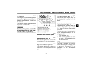 17
17 18
18 19
19 20
20 21
21 22
22 23
23 24
24 25
25 26
26 27
27 28
28 29
29 30
30 31
31 32
32 33
33 34
34 35
35 36
36 37
37 38
38 39
39 40
40 41
41 42
42 43
43 44
44 45
45 46
46 47
47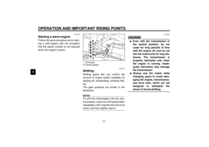 48
48 49
49 50
50 51
51 52
52 53
53 54
54 55
55 56
56 57
57 58
58 59
59 60
60 61
61 62
62 63
63 64
64 65
65 66
66 67
67 68
68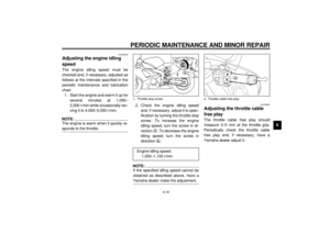 69
69 70
70 71
71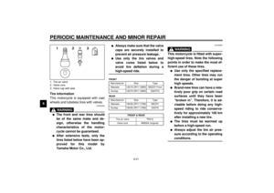 72
72 73
73 74
74 75
75 76
76 77
77 78
78 79
79 80
80 81
81 82
82 83
83 84
84 85
85 86
86 87
87 88
88 89
89 90
90 91
91 92
92 93
93 94
94 95
95 96
96 97
97 98
98 99
99 100
100 101
101 102
102 103
103 104
104 105
105 106
106 107
107 108
108 109
109 110
110 111
111 112
112 113
113 114
114 115
115
EW000071
WARNING
@ l
Make")