Page 33 of 116

INSTRUMENT AND CONTROL FUNCTIONS
3-18
3
EC000015
CAUTION:@ Never attempt to turn an adjusting
mechanism beyond the maximum
or minimum settings. @NOTE:@ Although the total number of clicks of a
damping force adjusting mechanism
may not exactly match the above spec-
ifications due to small differences in
production, the actual number of clicks
always represents the entire adjusting
range. To obtain a precise adjustment,
it would be advisable to check the num-
ber of clicks of each damping force ad-
justing mechanism and to modify the
specifications as necessary. @
EAU01570
Adjusting the shock absorber
assembly This shock absorber assembly is
equipped with a spring preload adjust-
ing ring and rebound and compression
damping force adjusting screws.
EC000015
CAUTION:@ Never attempt to turn an adjusting
mechanism beyond the maximum
or minimum settings. @
Spring preload
To increase the spring preload and
thereby harden the suspension, turn
the adjusting ring in direction
a. To de-
crease the spring preload and thereby
soften the suspension, turn the adjust-
ing ring in direction
b.NOTE:@ Align the appropriate notch in the ad-
justing ring with the position indicator
on the shock absorber.@CI-15E1. Spring preload adjusting ring
2. Special wrench
3. Position indicator
Minimum
(soft)Stan-
dardMaximum (hard)
Setting123 4 56789
E_5jj.book Page 18 Friday, September 8, 2000 3:33 PM
Page 34 of 116

INSTRUMENT AND CONTROL FUNCTIONS
3-19
3
Rebound damping force
To increase the rebound damping
force and thereby harden the rebound
damping, turn the adjusting screw in di-
rection
a. To decrease the rebound
damping force and thereby soften the
rebound damping, turn the adjusting
screw in direction
b.
CI-27E
Compression damping force
To increase the compression damping
force and thereby harden the compres-
sion damping, turn the adjusting screw
in direction
a. To decrease the com-
pression damping force and thereby
soften the compression damping, turn
the adjusting screw in direction
b.CI-27E
NOTE:@ Although the total number of clicks of a
damping force adjusting mechanism
may not exactly match the above spec-
ifications due to small differences in
production, the actual number of clicks
always represents the entire adjusting
range. To obtain a precise adjustment,
it would be advisable to check the num-
ber of clicks of each damping force ad-
justing mechanism and to modify the
specifications as necessary. @
1. Rebound damping force adjusting screwMinimum (soft) 11 clicks in direction
b*
Standard 7 clicks in direction
b*
Maximum (hard) 1 click in direction
b*
* With the adjusting screw fully turned in direction
a
1. Compression damping force adjusting screwMinimum (soft) 11 clicks in direction
b*
Standard 9 clicks in direction
b*
Maximum (hard) 1 click in direction
b*
* With the adjusting screw fully turned in direction
a
E_5jj.book Page 19 Friday, September 8, 2000 3:33 PM
Page 35 of 116
INSTRUMENT AND CONTROL FUNCTIONS
3-20
3
EAU00315
WARNING
@ This shock absorber contains high-
ly pressurized nitrogen gas. For
proper handling, read and under-
stand the following information be-
fore handling the shock absorber.
The manufacturer cannot be held re-
sponsible for property damage or
personal injury that may result from
improper handling.l
Do not tamper with or attempt to
open the gas cylinder.
l
Do not subject the shock ab-
sorber to an open flame or other
high heat sources, otherwise it
may explode due to excessive
gas pressure.
l
Do not deform or damage the
gas cylinder in any way, as this
will result in poor damping
performance.
l
Always have a Yamaha dealer
service the shock absorber.
@
E_5jj.book Page 20 Friday, September 8, 2000 3:33 PM
Page 36 of 116
INSTRUMENT AND CONTROL FUNCTIONS
3-21
3
EAU01580
Matching the front and rear suspension settings Use this table as a guide to match the suspension and damping adjustments of the front fork and shock absorber assembly
according to various load conditions.CI-31E
EC000015CAUTION:@ Never attempt to turn an adjusting mechanism beyond the maximum or minimum settings. @
Load condition Front fork adjustment Shock absorber assembly adjustment
Spring preloadCompression
damping forceRebound
damping forceSpring preloadCompression
damping forceRebound
damping force
Rider only 1–8 1–9 1–11 1–7 4–11 3–11
With passenger 1–8 1–9 1–11 4–9 1–9 1–7
E_5jj.book Page 21 Friday, September 8, 2000 3:33 PM
Page 37 of 116

INSTRUMENT AND CONTROL FUNCTIONS
3-22
3
EAU03170
Luggage strap holders There are four luggage strap holders
on the bottom of the passenger seat.
To use the strap holders, remove the
passenger seat, unhook the straps,
and then install the seat with the straps
hanging out from under the passenger
seat. (See page 3-14 for passenger
seat removal and installation
procedures.)
EAU01571
EXUP systemThis motorcycle is equipped with
Yamaha’s EXUP (EXhaust Ultimate
Power valve) system. This system
boosts engine power by means of a
valve that regulates the diameter of the
exhaust pipe. The EXUP system valve
is constantly adjusted in accordance
with the engine speed by a computer-
controlled servomotor.
EC000027
CAUTION:@ l
The EXUP system has been set
and extensively tested at the
Yamaha factory. Changing
these settings without sufficient
technical knowledge may result
in poor performance of or dam-
age to the engine.
l
If the EXUP system does not op-
erate, have a Yamaha dealer
check it.
@
1. Luggage strap holder (´ 4)
2. Hook (´ 4)
E_5jj.book Page 22 Friday, September 8, 2000 3:33 PM
Page 38 of 116

INSTRUMENT AND CONTROL FUNCTIONS
3-23
3
EAU00330
SidestandThe sidestand is located on the left side
of the frame. Raise the sidestand or
lower it with your foot while holding the
motorcycle upright.NOTE:@ The built-in sidestand switch is part of
the ignition circuit cut-off system, which
cuts the ignition in certain situations.
(See further down for an explanation of
the ignition circuit cut-off system.) @
EW000044
WARNING
@ The motorcycle must not be ridden
with the sidestand down, or if the
sidestand cannot be properly
moved up (or does not stay up), oth-
erwise the sidestand could contact
the ground and distract the opera-
tor, resulting in a possible loss of
control. Yamaha’s ignition circuit
cut-off system has been designed to
assist the operator in fulfilling the
responsibility of raising the side-
stand before starting off. Therefore,
check this system regularly as de-
scribed below and have a Yamaha
dealer repair it if it does not function
properly. @
EAU00331
Ignition circuit cut-off systemThe ignition circuit cut-off system (com-
prising the sidestand switch, clutch
switch and neutral switch) has the fol-
lowing functions.l
It prevents starting when the trans-
mission is in gear and the side-
stand is up, but the clutch lever is
not pulled.
l
It prevents starting when the trans-
mission is in gear and the clutch
lever is pulled, but the sidestand is
still down.
l
It cuts the running engine when
the sidestand is moved down.
Periodically check the operation of the
ignition circuit cut-off system according
to the following procedure.
EW000045
WARNING
@ If a malfunction is noted, have a
Yamaha dealer check the system
before riding. @
E_5jj.book Page 23 Friday, September 8, 2000 3:33 PM
Page 39 of 116

INSTRUMENT AND CONTROL FUNCTIONS
3-24
3
CD-21E
With the engine turned off:
1. Move the sidestand down.
2. Make sure that the engine stop switch is set to “ ”.
3. Turn the key to “ON”.
4. Shift the transmission into the neutral position.
5. Push the start switch.
Does the engine start?
The neutral switch may be defective.
The motorcycle should not be ridden until
checked by a Yamaha dealer.
With the engine still running:
6. Move the sidestand up.
7. Keep the clutch lever pulled.
8. Shift the transmission into gear.
9. Move the sidestand down.
Does the engine stall?After the engine has stalled:
10. Move the sidestand up.
11. Keep the clutch lever pulled.
12. Push the start switch.
Does the engine start?
The sidestand switch may be defective.
The motorcycle should not be ridden until
checked by a Yamaha dealer.The clutch switch may be defective.
The motorcycle should not be ridden until
checked by a Yamaha dealer.
NO
NOTE:This check is most reliable if performed with
a warmed-up engine.
YESYES NO
The system is OK.
The motorcycle can be ridden.
YES NO
E_5jj.book Page 24 Friday, September 8, 2000 3:33 PM
Page 40 of 116
E_5jj.book Page 25 Friday, September 8, 2000 3:33 PM
 1
1 2
2 3
3 4
4 5
5 6
6 7
7 8
8 9
9 10
10 11
11 12
12 13
13 14
14 15
15 16
16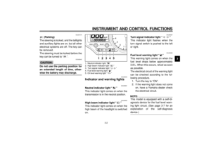 17
17 18
18 19
19 20
20 21
21 22
22 23
23 24
24 25
25 26
26 27
27 28
28 29
29 30
30 31
31 32
32 33
33 34
34 35
35 36
36 37
37 38
38 39
39 40
40 41
41 42
42 43
43 44
44 45
45 46
46 47
47 48
48 49
49 50
50 51
51 52
52 53
53 54
54 55
55 56
56 57
57 58
58 59
59 60
60 61
61 62
62 63
63 64
64 65
65 66
66 67
67 68
68 69
69 70
70 71
71 72
72 73
73 74
74 75
75 76
76 77
77 78
78 79
79 80
80 81
81 82
82 83
83 84
84 85
85 86
86 87
87 88
88 89
89 90
90 91
91 92
92 93
93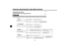 94
94 95
95 96
96 97
97 98
98 99
99 100
100 101
101 102
102 103
103 104
104 105
105 106
106 107
107 108
108 109
109 110
110 111
111 112
112 113
113 114
114 115
115

