Page 2550 of 4323
I15902
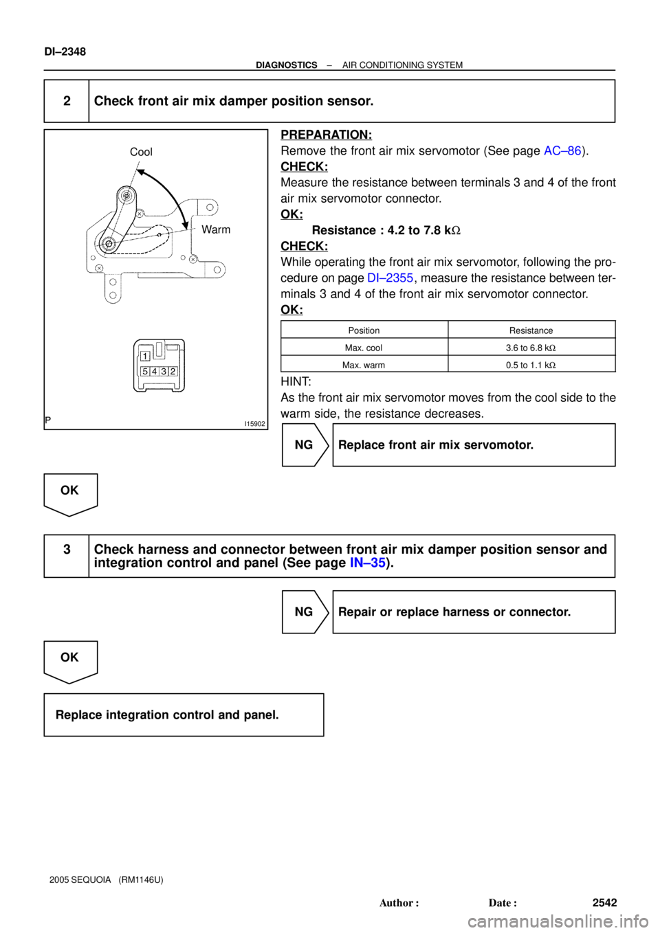
Cool
Warm
DI±2348
± DIAGNOSTICSAIR CONDITIONING SYSTEM
2542 Author�: Date�:
2005 SEQUOIA (RM1146U)
2 Check front air mix damper position sensor.
PREPARATION:
Remove the front air mix servomotor (See page AC±86).
CHECK:
Measure the resistance between terminals 3 and 4 of the front
air mix servomotor connector.
OK:
Resistance : 4.2 to 7.8 kW
CHECK:
While operating the front air mix servomotor, following the pro-
cedure on page DI±2355, measure the resistance between ter-
minals 3 and 4 of the front air mix servomotor connector.
OK:
PositionResistance
Max. cool3.6 to 6.8 kW
Max. warm0.5 to 1.1 kW
HINT:
As the front air mix servomotor moves from the cool side to the
warm side, the resistance decreases.
NG Replace front air mix servomotor.
OK
3 Check harness and connector between front air mix damper position sensor and
integration control and panel (See page IN±35).
NG Repair or replace harness or connector.
OK
Replace integration control and panel.
Page 2551 of 4323

4
1
0
100 %
TPI terminal voltage
Damper opening angle
I15866
A16
Air Inlet Control
Servomotor
1
Y±R 2 311
16
13S5±AI
TPI
SG±TPI Integration Control
and Panel
I20 L±B
W VZ
PT
GNDI20
I20
± DIAG")
(V)
4
1
0
100 %
TPI terminal voltage
Damper opening angle
I15866
A16
Air Inlet Control
Servomotor
1
Y±R 2 311
16
13S5±AI
TPI
SG±TPI Integration Control
and Panel
I20 L±B
W VZ
PT
GNDI20
I20
± DIAGNOSTICSAIR CONDITIONING SYSTEM
DI±2349
2543 Author�: Date�:
2005 SEQUOIA (RM1146U)
DTC 32 Air Inlet Damper Position Sensor Circuit
CIRCUIT DESCRIPTION
This sensor detects the position of the air inlet damper and
sends the appropriate signals to the integration control and
panel.
The position sensor is built into the air inlet damper control ser-
vomotor assembly.
DTC No.Detection ItemTrouble Area
32Short to ground or short to power source circuit in air inlet
�Air inlet damper position sensor
�Harness or connector between air inlet damper position sen-
32Short to ground or short to ower source circuit in air inlet
damper position sensor circuit.
�Harness or connector between air inlet dam er osition sen-
sor and integration control and panel
�Integration control and panel
WIRING DIAGRAM
DI3FG±10
Page 2552 of 4323
I28847
SG±TPI TPII20 Integration Control and Panel:
DI±2350
± DIAGNOSTICSAIR CONDITIONING SYSTEM
2544 Author�: Date�:
2005 SEQUOIA (RM1146U)
INSPECTION PROCEDURE
1 Check voltage between terminals TPI and SG±TPI of integration control and pan-
el.
PREPARATION:
Remove the integration control and panel with connectors still
connected.
CHECK:
(a) Turn the ignition switch to ON.
(b) Press the REC/FRS switch to change air inlet between
fresh and recirculation air, and measure the voltage be-
tween terminals TPI and SG±TPI of the integration con-
trol and panel when the air inlet damper control servomo-
tor operates.
OK:
FRS±REC SwitchVoltage
REC3.5 to 4.5 V
FRS0.5 to 1.5 V
HINT:
As the air inlet damper control servomotor is moved from the
REC side to the FRS side, the voltage decreases.
NG Go to step 2.
OK
Proceed to next circuit inspection shown in problem symptoms table (See page DI±2304). How-
ever, if DTC 32 or 42 is displayed, replace integration control and panel.
Page 2553 of 4323
I25201
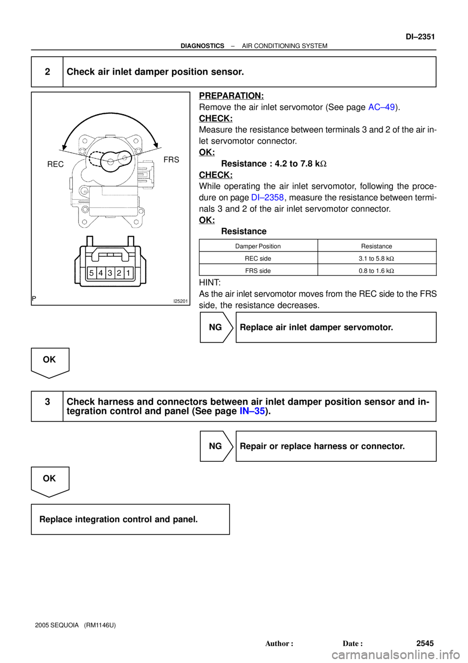
RECFRS
± DIAGNOSTICSAIR CONDITIONING SYSTEM
DI±2351
2545 Author�: Date�:
2005 SEQUOIA (RM1146U)
2 Check air inlet damper position sensor.
PREPARATION:
Remove the air inlet servomotor (See page AC±49).
CHECK:
Measure the resistance between terminals 3 and 2 of the air in-
let servomotor connector.
OK:
Resistance : 4.2 to 7.8 kW
CHECK:
While operating the air inlet servomotor, following the proce-
dure on page DI±2358, measure the resistance between termi-
nals 3 and 2 of the air inlet servomotor connector.
OK:
Resistance
Damper PositionResistance
REC side3.1 to 5.8 kW
FRS side0.8 to 1.6 kW
HINT:
As the air inlet servomotor moves from the REC side to the FRS
side, the resistance decreases.
NG Replace air inlet damper servomotor.
OK
3 Check harness and connectors between air inlet damper position sensor and in-
tegration control and panel (See page IN±35).
NG Repair or replace harness or connector.
OK
Replace integration control and panel.
Page 2554 of 4323

1
TP terminal voltage0 100 %
(Cool)
(Hot)
Damper opening angle
I28838
A34 A/C Water Valve (Rear)
3 2
1
W W
5L±Y1
10
18RrS5
RrSG
RrTP Integration Control
and Panel
I21
L±R L±Y
O IJ3 BH1
L±R 7")
4 (V)
1
TP terminal voltage0 100 %
(Cool)
(Hot)
Damper opening angle
I28838
A34 A/C Water Valve (Rear)
3 2
1
W W
5L±Y1
10
18RrS5
RrSG
RrTP Integration Control
and Panel
I21
L±R L±Y
O IJ3 BH1
L±R 7
L±Y
1
W
A L±R
IG
J/C
J438
6
(Shielded)
6 BH1
BH116 w/ Rear A/C:
(Shielded)
O
A VZ
GND
PTI21
I21 IJ3
IJ3
IJ3 DI±2352
± DIAGNOSTICSAIR CONDITIONING SYSTEM
2546 Author�: Date�:
2005 SEQUOIA (RM1146U)
DTC 37 Water Valve Damper Position Sensor Circuit
CIRCUIT DESCRIPTION
This sensor detects the position of the air mix damper and
sends the appropriate signals to the integration control and
panel.
The position sensor is built into the water valve damper control
servomotor assembly.
DTC No.Detection ItemTrouble Area
37Short to ground or short to power source circuit in water valve
�Water valve damper position sensor
�Harness or connector between water valve damper position
37Short to ground or short to ower source circuit in water valve
damper position sensor circuit.
�Harness or connector between water valve dam er osition
sensor and integration control and panel
�Integration control and panel
WIRING DIAGRAM
DI3FH±14
Page 2555 of 4323
I28847
RrSG
RrTPI21 Integration Control and Panel:
± DIAGNOSTICSAIR CONDITIONING SYSTEM
DI±2353
2547 Author�: Date�:
2005 SEQUOIA (RM1146U)
INSPECTION PROCEDURE
1 Check voltage between terminals RrTP and RrSG of integration control and pan-
el.
PREPARATION:
Remove the integration control and panel with connectors still
connected.
CHECK:
(a) Turn the ignition switch to ON.
(b) Change the set temperature to activate the water valve
servomotor and measure the voltage between terminals
RrTP and RrSG of the integration control and panel con-
nector each time the set temperature is changed.
OK:
Set TemperatureVoltage
Max. cool3.5 to 4.5 V
Max. hot0.5 to 1.5 V
HINT:
As the set temperature increases, the voltage decreases.
NG Go to step 2.
OK
Proceed to next circuit inspection shown in problem symptoms table (See page DI±2304). How-
ever, if DTC 37 or 47 is displayed, replace integration control and panel.
Page 2556 of 4323
I28852
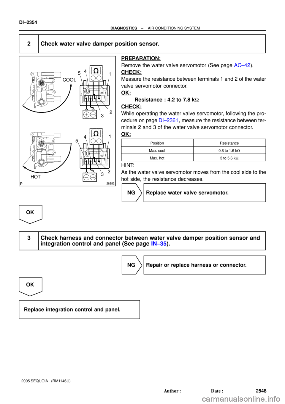
HOTCOOL
4
532 4
5
2
3
1
1
DI±2354
± DIAGNOSTICSAIR CONDITIONING SYSTEM
2548 Author�: Date�:
2005 SEQUOIA (RM1146U)
2 Check water valve damper position sensor.
PREPARATION:
Remove the water valve servomotor (See page AC±42).
CHECK:
Measure the resistance between terminals 1 and 2 of the water
valve servomotor connector.
OK:
Resistance : 4.2 to 7.8 kW
CHECK:
While operating the water valve servomotor, following the pro-
cedure on page DI±2361, measure the resistance between ter-
minals 2 and 3 of the water valve servomotor connector.
OK:
PositionResistance
Max. cool0.8 to 1.6 kW
Max. hot3 to 5.6 kW
HINT:
As the water valve servomotor moves from the cool side to the
hot side, the resistance decreases.
NG Replace water valve servomotor.
OK
3 Check harness and connector between water valve damper position sensor and
integration control and panel (See page IN±35).
NG Repair or replace harness or connector.
OK
Replace integration control and panel.
Page 2557 of 4323
I28839
A17 Air Mix Damper
Control Servomotor (Front)
1
210
9AMH
AMC Integration Control and Panel
R±L
W±LI20 MHOT
I20 MCOOL
± DIAGNOSTICSAIR CONDITIONING SYSTEM
DI±2355
2549 Author�: Date�:
DTC 41 Front Air Mix Damper Control Servomotor
Circuit
CIRCUIT DESCRIPTION
The front air mix damper control servomotor is controlled by the integration control and panel and moves
the air mix damper to the desired position.
DTC No.Detection ItemTrouble Area
41
Air mix damper position sensor value does not change even if
integration control and panel operates air mix damper control
servomotor.
�Front air mix damper control servomotor
�Front air mix damper position sensor
�Harness or connector between front air mix position sensor
and integration control and panel
�Harness or connector between air mix damper control servo-
motor and integration control and panel
�Integration control and panel
WIRING DIAGRAM
DI3FI±15