Page 3806 of 4323

REMOVAL
1. DISCHARGE REFRIGERANT FROM REFRIGERATION
SYSTEM
HINT:
At the time of ins")
AC3I9±02
I21380
I21383
± AIR CONDITIONINGREAR A/C EVAPORATOR
AC±71
3798 Author�: Date�:
2005 SEQUOIA (RM1146U)
REMOVAL
1. DISCHARGE REFRIGERANT FROM REFRIGERATION
SYSTEM
HINT:
At the time of installation, refer to the following:
�Evacuate air from the refrigeration system.
�Charge the system with refrigerant and inspect for leak-
age of refrigerant.
Specified amount:
Dual A/C: 1050 ± 50 g (37.03 ± 1.76 oz.)
2. DRAIN ENGINE COOLANT FROM RADIATOR
HINT:
It is not necessary to drain out all coolant.
3. REMOVE REAR SEAT OUTER BELT FLOOR AN-
CHORS
4. REMOVE BACKDOOR SCUFF PLATE
5. REMOVE REAR DOOR SCUFF PLATE RH
6. REMOVE UPPER BACK DOOR GARNISH
7. REMOVE REAR WINDOW SIDE GARNISH RH
8. REMOVE REAR QUARTER TRIM PANEL RH
9. REMOVE QUARTER PILLAR GARNISH RH
10. DISCONNECT LIQUID AND SUCTION TUBES
Remove the 2 bolts and disconnect both tubes.
Torque: 5.4 N´m (55 kgf´cm, 48 in.´lbf)
NOTICE:
Cap the openings immediately to keep moisture or dirt out
of the system.
HINT:
At the time of installation, refer to the following:
Lubricate 2 new O±rings with compressor oil and install them
to the tubes.
11. REMOVE AIR DUCT
(a) Remove the 3 clips and cover.
(b) Remove the 2 air ducts.
(c) Disconnect the connectors and wire harness clamps.
Page 3807 of 4323
I21799
I21384
I21800
AC±72
± AIR CONDITIONINGREAR A/C EVAPORATOR
3799 Author�: Date�:
2005 SEQUOIA (RM1146U)
12. REMOVE EXPANSION VALVE
(a) Remove the 4 screws and 2 brackets.
(b) Pry out the packing.
HINT:
At the time of installation, refer to the following item:
Do not refuse the packing.
(c) Using a hexagon wrench (5.0 mm (0.20 in.)), remove the
2 bolts.
Torque: 5.4 N´m (55 kgf´cm, 48 in.´lbf)
(d) Remove the 3 bolts.
(e) Lift the A/C unit until the tube and accessary can be re-
moved.
(f) Remove the tube and accessary.
13. REMOVE EVAPORATOR
(a) Remove the 8 screws and cover.
(b) Pull out the evaporator.
Page 3809 of 4323

REAR A/C EXPANSION VALVE
REMOVAL
1. DISCHARGE REFRIGERANT FROM REFRIGERATION")
AC3IB±02
I21380
I21383
AC±74
± AIR CONDITIONINGREAR A/C EXPANSION VALVE
3801 Author�: Date�:
2005 SEQUOIA (RM1146U)
REAR A/C EXPANSION VALVE
REMOVAL
1. DISCHARGE REFRIGERANT FROM REFRIGERATION
SYSTEM
HINT:
At the time of installation, refer to the following:
�Evacuate air from the refrigeration system.
�Charge the system with refrigerant and inspect for leak-
age of refrigerant.
Specified amount:
Dual A/C: 1050 ± 50 g (37.03 ± 1.76 oz.)
2. DRAIN ENGINE COOLANT FROM RADIATOR
HINT:
It is not necessary to drain out all coolant.
3. REMOVE REAR SEAT OUTER BELT FLOOR AN-
CHORS
4. REMOVE BACKDOOR SCUFF PLATE
5. REMOVE REAR DOOR SCUFF PLATE RH
6. REMOVE UPPER BACK DOOR GARNISH
7. REMOVE REAR WINDOW SIDE GARNISH RH
8. REMOVE REAR QUARTER TRIM PANEL RH
9. REMOVE QUARTER PILLAR GARNISH RH
10. DISCONNECT LIQUID AND SUCTION TUBES
Remove the 2 bolts and disconnect both tubes.
Torque: 5.4 N´m (55 kgf´cm, 48 in.´lbf)
NOTICE:
Cap the openings immediately to keep moisture or dirt out
of the system.
HINT:
At the time of installation, refer to the following:
Lubricate 2 new O±rings with compressor oil and install them
to the tubes.
11. REMOVE AIR DUCT
(a) Remove the 3 clips and cover.
(b) Remove the 2 air ducts.
(c) Disconnect the connectors and wire harness clamps.
Page 3810 of 4323
I21799
I21384
I21387
Nut A:
Nut B:
± AIR CONDITIONINGREAR A/C EXPANSION VALVE
AC±75
3802 Author�: Date�:
2005 SEQUOIA (RM1146U)
12. REMOVE EXPANSION VALVE
(a) Remove the 4 screws and 2 brackets.
(b) Pry out the packing.
HINT:
At the time of installation, refer to the following:
Do not refuse the packing.
(c) Using a hexagon wrench (5.0 mm (0.20 in.)), remove the
2 bolts.
Torque: 5.4 N´m (55 kgf´cm, 48 in.´lbf)
(d) Remove the 3 bolts.
(e) Lift the A/C unit until the tube and accessary can be re-
moved.
(f) Remove the tube and accessary.
(g) Remove the holder and disconnect the heat sensing
tube.
(h) Loosen the 2 nuts and remove the expansion valve.
Torque:
Nut A: 13 N´m (135 kgf´cm, 10 in.´lbf)
Nut B: 22 N´m (235 kgf´cm, 16 in.´lbf)
HINT:
At the time of installation, refer to the following:
Lubricate 2 new O±rings with compressor oil and install them
to the expansion valve.
Page 3828 of 4323
AC1LT±05
I21452
± AIR CONDITIONINGPRESSURE SWITCH
AC±93
3820 Author�: Date�:
2005 SEQUOIA (RM1146U)
REMOVAL
1. DISCHARGE REFRIGERANT FROM REFRIGERATION
SYSTEM
HINT:
At the time of installation, refer to the following:
�Evacuate air from the refrigeration system.
�Charge the system with refrigerant and inspect for leak-
age of refrigerant.
Specified amount:
Single A/C: 750 ± 50 g (26.45 ± 1.76 oz.)
Dual A/C: 1050 ± 50 g (37.03 ± 1.76 oz.)
2. REMOVE PRESSURE SWITCH FROM LIQUID TUBE
Disconnect the connector and remove the pressure switch.
Torque: 10 N´m (100 kgf´cm, 7 ft´lbf)
HINT:
�Being careful not to deform the tube, lock the switch
mounted on the tube with an open end wrench and re-
move the switch.
�At the time of installation, refer to the following:
Lubricate a new O±ring with the compressor oil and install
it to the switch.
Page 4254 of 4323
05_SEQUOIA_U (L/O 0408)
395
2005 SEQUOIA from Aug. '04 Prod. (OM34424U)
Tighten each nut a little at a time in
the order shown. Repeat the process
until all the nuts are tight.
CAUTION
�When lowering the vehicle,
make sure all portions of your
body and all other persons
around will not be injured as
the vehicle is lowered to the
ground.
�Have the wheel nuts tightened
with torque wrench to 110 N´m
(11.5 kgf´m, 83 ft´lbf), as soon
as possible after changing
wheels. Otherwise, the nuts
may loosen and the wheels
may fall off, which could cause
a serious accident.
Ty p e A
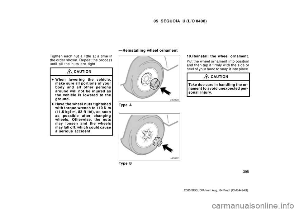
Ty p e B10.Reinstall the wheel ornament.
Put the wheel ornament into position
and then tap it firmly with the side or
heel of your hand to snap it into place.
CAUTION
Take due care in handling the or-
nament to avoid unexpected per-
sonal injury.
ÐReinstalling wheel ornament
Page 4255 of 4323

396
2005 SEQUOIA from Aug. 04 Prod. (OM34424U)
11. Check the air pressure of the re-
placed tire.
Adjust the air pressure to the specifi-
cation designated on page 458 in
Sect")
05_SEQUOIA_U (L/O 0408)
396
2005 SEQUOIA from Aug. '04 Prod. (OM34424U)
11. Check the air pressure of the re-
placed tire.
Adjust the air pressure to the specifi-
cation designated on page 458 in
Section 8. If the pressure is lower,
drive slowly to the nearest service
station and fill to the correct pressure.
Do not forget to reinstall the tire infla-
tion valve cap as dirt and moisture
could get into the valve core and
possibly cause air leakage. If the cap
is missing, have a new one put on as
soon as possible.
12.Restow all the tools, jack and
flat tire securely.
With a spare tire of the same wheel
type as the installed tiresÐ
As soon after changing wheels as
possible, tighten the wheel nuts to the
torque specified on page 458 in Sec-
tion 8 with a torque wrench. Have a
technician repair the flat tire.With a spare tire of different wheel
type from the installed tiresÐ
As soon after changing wheels as
possible, tighten the wheel nuts to the
torque specified on page 458 in Sec-
tion 8 with a torque wrench. Have a
technician repair the flat tire and re-
place the spare tire with it.
Initial adjustment of the tire pres-
sure warning system is necessary
after you have replaced your tires
or wheels. See ªTire pressure
warning systemº on page 198 in
Section 1±7.
CAUTION
Before driving, make sure all the
tools, jack and flat tire are se-
curely in place in their storage
location to reduce the possibility
of personal injury during a colli-
sion or sudden braking.
If your vehicle becomes stuck in snow,
mud, sand, etc., then you may attempt
to rock the vehicle free by moving it
forward and backward.
Two±wheel drive modelsÐTurn off the
traction control system to become un-
stuck to allow the tires to spin enough
to remove the vehicle from the obstruc-
tion. (For details, see ªTraction control
systemº on page 182 in Section 1±7.)
CAUTION
Do not attempt to rock the vehicle
free by moving it forward and back-
ward if people or objects are any-
where near the vehicle. During the
rocking operation the vehicle may
suddenly move forward or backward
as it becomes unstuck, causing injury
or damage to nearby people or ob-
jects.
ÐAfter changing wheels If your vehicle becomes stuck