Page 2463 of 4323
± DIAGNOSTICSNAVIGATION SYSTEM
DI±2261
2455 Author�: Date�:
2005 SEQUOIA (RM1146U)
INSPECTION PROCEDURE
NOTICE:
The vehicle is equipped with SRS (Supplemental Restraint System) such as airbags. Before servic-
ing (including removal or installation of parts), be sure to read the precautionary notice for the sup-
plemental restraint system (See page RS±1).
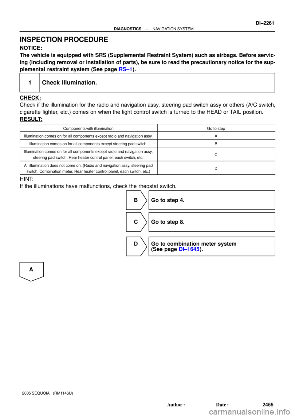
1 Check illumination.
CHECK:
Check if the illumination for the radio and navigation assy, steering pad switch assy or others (A/C switch,
cigarette lighter, etc.) comes on when the light control switch is turned to the HEAD or TAIL position.
RESULT:
Components with illuminationGo to step
Illumination comes on for all components except radio and navigation assy.A
Illumination comes on for all components except steering pad switch.B
Illumination comes on for all components except radio and navigation assy,
steering pad switch, Rear heater control panel, each switch, etc.C
All illumination does not come on. (Radio and navigation assy, steering pad
switch, Combination meter, Rear heater control panel, each switch, etc.)D
HINT:
If the illuminations have malfunctions, check the rheostat switch.
B Go to step 4.
C Go to step 8.
D Go to combination meter system
(See page DI±1645).
A
Page 2490 of 4323
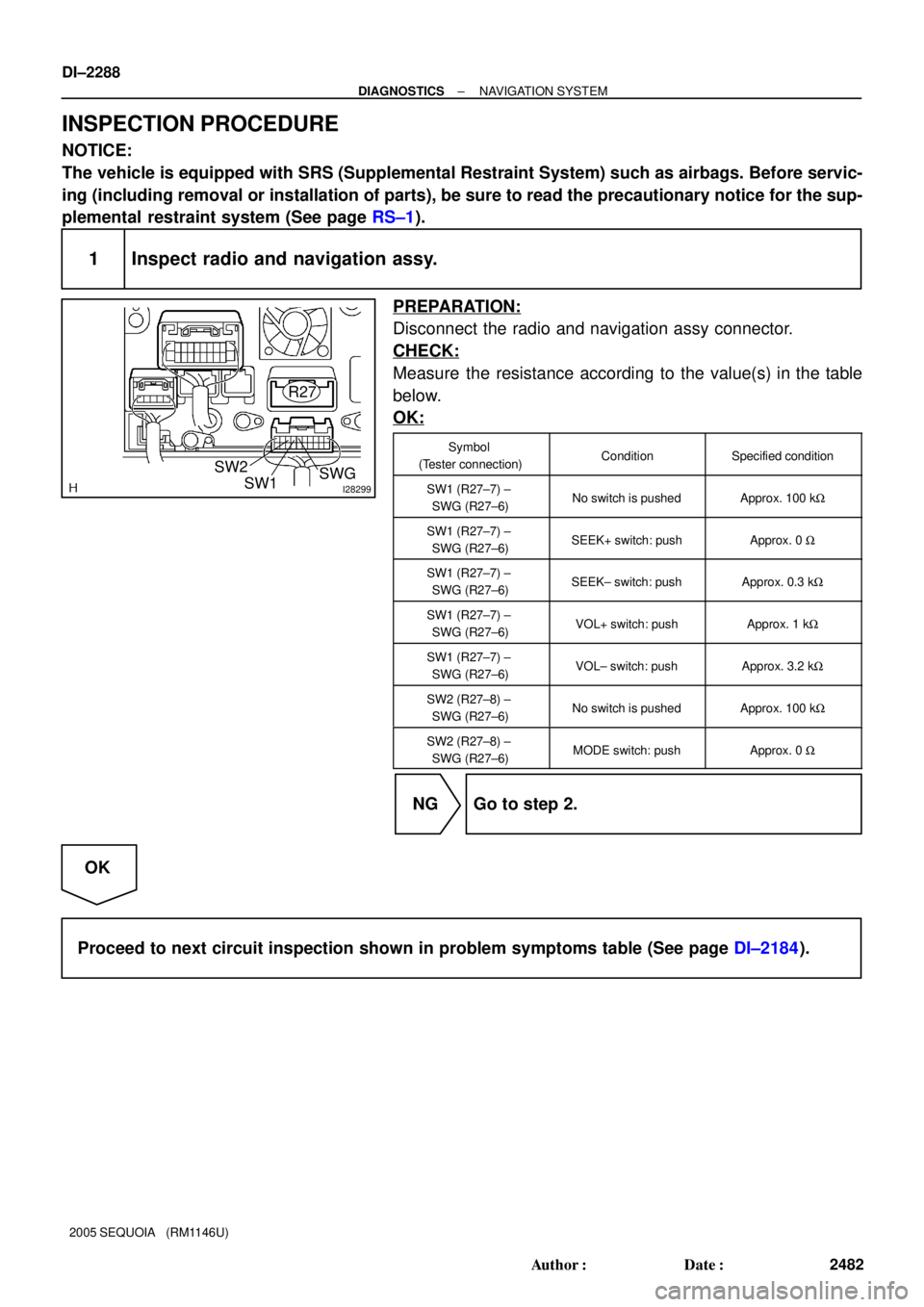
I28299SW1 SW2SWG
R27
DI±2288
± DIAGNOSTICSNAVIGATION SYSTEM
2482 Author�: Date�:
2005 SEQUOIA (RM1146U)
INSPECTION PROCEDURE
NOTICE:
The vehicle is equipped with SRS (Supplemental Restraint System) such as airbags. Before servic-
ing (including removal or installation of parts), be sure to read the precautionary notice for the sup-
plemental restraint system (See page RS±1).
1 Inspect radio and navigation assy.
PREPARATION:
Disconnect the radio and navigation assy connector.
CHECK:
Measure the resistance according to the value(s) in the table
below.
OK:
Symbol
(Tester connection)ConditionSpecified condition
SW1 (R27±7) ±
SWG (R27±6)No switch is pushedApprox. 100 kW
SW1 (R27±7) ±
SWG (R27±6)SEEK+ switch: pushApprox. 0 W
SW1 (R27±7) ±
SWG (R27±6)SEEK± switch: pushApprox. 0.3 kW
SW1 (R27±7) ±
SWG (R27±6)VOL+ switch: pushApprox. 1 kW
SW1 (R27±7) ±
SWG (R27±6)VOL± switch: pushApprox. 3.2 kW
SW2 (R27±8) ±
SWG (R27±6)No switch is pushedApprox. 100 kW
SW2 (R27±8) ±
SWG (R27±6)MODE switch: pushApprox. 0 W
NG Go to step 2.
OK
Proceed to next circuit inspection shown in problem symptoms table (See page DI±2184).
Page 2500 of 4323
DI±2298
± DIAGNOSTICSAIR CONDITIONING SYSTEM
2492 Author�: Date�:
2005 SEQUOIA (RM1146U)
9. SUPPLEMENTAL RESTRAINT SYSTEM (SRS)
The SEQUOIA is equipped with an SRS (Supplemental Re-
straint System) such as the driver, passenger, side, curtain
shield airbag. Failure to carry out service operation in the cor-
rect sequence could cause the SRS to unexpectedly deploy
during servicing, possibly leading to a serious accident. Before
servicing (including removal or installation of parts, inspection
or replacement), be sure to read the precautionary notices tn
the RS section.
10. INITIALIZATION
NOTICE:
When disconnecting the battery terminal, initialize the fol-
lowing system after the terminal is reconnected.
System NameSee Page
Back Door Power Window Control Sys-
temBE±77
Page 3236 of 4323
SR01S±06
± STEERINGSTEERING SYSTEM
SR±1
3228 Author�: Date�:
2005 SEQUOIA (RM1146U)
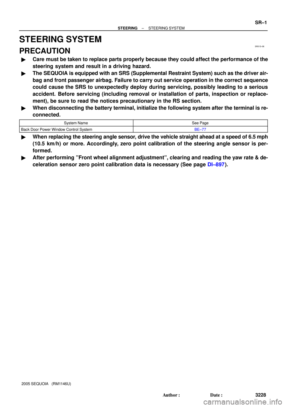
STEERING SYSTEM
PRECAUTION
�Care must be taken to replace parts properly because they could affect the performance of the
steering system and result in a driving hazard.
�The SEQUOIA is equipped with an SRS (Supplemental Restraint System) such as the driver air-
bag and front passenger airbag. Failure to carry out service operation in the correct sequence
could cause the SRS to unexpectedly deploy during servicing, possibly leading to a serious
accident. Before servicing (including removal or installation of parts, inspection or replace-
ment), be sure to read the notices precautionary in the RS section.
�When disconnecting the battery terminal, initialize the following system after the terminal is re-
connected.
System NameSee Page
Back Door Power Window Control SystemBE±77
�When replacing the steering angle sensor, drive the vehicle straight ahead at a speed of 6.5 mph
(10.5 km/h) or more. Accordingly, zero point calibration of the steering angle sensor is per-
formed.
�After performing ºFront wheel alignment adjustmentº, clearing and reading the yaw rate & de-
celeration sensor zero point calibration data is necessary (See page DI±897).
Page 3246 of 4323

F16017
Steering Column
Upper Cover
New Marked
Line
Steering Wheel
R00429
Marked Line
F16018
± STEERINGSTEERING WHEEL
SR±11
3238 Author�: Date�:
2005 SEQUOIA (RM1146U)
(d) Turn the steering wheel to its straight position.
HINT:
Refer to the upper surface of the steering wheel, steering spoke
and SRS airbag line for the straight position.
(e) Draw a new line on the masking tape of the steering wheel
as shown in the illustration.
(f) Measure the distance between the 2 lines on the masking
tape of the steering wheel.
(g) Convert the measured distance to steering angle.
Measured distance 1 mm (0.04 in.) = Steering angle
approximately 1 deg.
HINT:
Make a note of the steering angle.
2. ADJUST STEERING ANGLE
(a) Draw a line on the RH and LH tie rod and rack ends where
it can easily be seen.
(b) Using a paper gauge, measure the distance from RH and
LH tie rod ends to the rack end screws.
HINT:
�Measure the RH side and LH side.
�Make a note of the measured values.
(c) Remove the RH and LH boot clips from the rack boots.
(d) Loosen the RH and LH lock nuts.
(e) Turn the RH and LH rack end by the same amount (but
in different directions) according to the steering angle.
1 turn 360 deg. of rack end (1.5 mm (0.059 in.) horizon-
tal movement) = 12 deg. of steering angle
(f) Tighten the RH and LH lock nuts.
Torque: 55 N´m (560 kgf´cm, 41 ft´lbf)
NOTICE:
Make sure that the difference in length between RH and LH
tie rod ends and rack end screws are within 1.5 mm (0.059
in.).
(g) Install the RH and LH boot clips.
Page 3249 of 4323
SR1KD±01
F17124
Screw CaseTorx® Screw
F17904
Correct
Wrong
Airbag Connectors
F06699
Matchmarks
SST
SR±14
± STEERINGTILT STEERING COLUMN
3241 Author�: Date�:
2005 SEQUOIA (RM1146U)
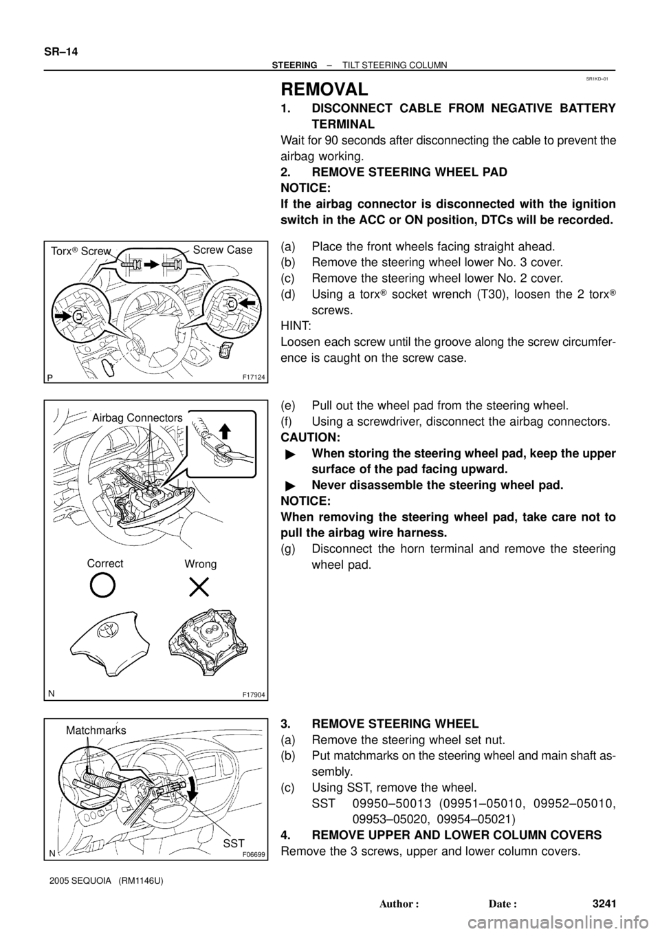
REMOVAL
1. DISCONNECT CABLE FROM NEGATIVE BATTERY
TERMINAL
Wait for 90 seconds after disconnecting the cable to prevent the
airbag working.
2. REMOVE STEERING WHEEL PAD
NOTICE:
If the airbag connector is disconnected with the ignition
switch in the ACC or ON position, DTCs will be recorded.
(a) Place the front wheels facing straight ahead.
(b) Remove the steering wheel lower No. 3 cover.
(c) Remove the steering wheel lower No. 2 cover.
(d) Using a torx® socket wrench (T30), loosen the 2 torx®
screws.
HINT:
Loosen each screw until the groove along the screw circumfer-
ence is caught on the screw case.
(e) Pull out the wheel pad from the steering wheel.
(f) Using a screwdriver, disconnect the airbag connectors.
CAUTION:
�When storing the steering wheel pad, keep the upper
surface of the pad facing upward.
�Never disassemble the steering wheel pad.
NOTICE:
When removing the steering wheel pad, take care not to
pull the airbag wire harness.
(g) Disconnect the horn terminal and remove the steering
wheel pad.
3. REMOVE STEERING WHEEL
(a) Remove the steering wheel set nut.
(b) Put matchmarks on the steering wheel and main shaft as-
sembly.
(c) Using SST, remove the wheel.
SST 09950±50013 (09951±05010, 09952±05010,
09953±05020, 09954±05021)
4. REMOVE UPPER AND LOWER COLUMN COVERS
Remove the 3 screws, upper and lower column covers.
Page 3250 of 4323
F17896
A
BMatchmarks
F13260
F06703
± STEERINGTILT STEERING COLUMN
SR±15
3242 Author�: Date�:
2005 SEQUOIA (RM1146U)
5. REMOVE COMBINATION SWITCH WITH SPIRAL
CABLE
(a) Disconnect the 4 connectors.
(b) Disconnect the airbag connector.
(c) Remove the 3 screws and combination switch.
6. REMOVE SPIRAL CABLE (See page BE±26)
NOTICE:
Do not disassemble the cable or apply oil to it.
7. REMOVE COWL SIDE TRIM AND FRONT DOOR
SCUFF PLATE
8. REMOVE LOWER LH FINISH PANEL
(a) Remove the 2 screws and disconnect the hood lock re-
lease lever from the panel.
(b) Remove the 4 panel set bolts and lower LH finish panel.
9. REMOVE NO. 2 HEATER TO REGISTER DUCT
10. REMOVE BRAKE PEDAL RETURN SPRING
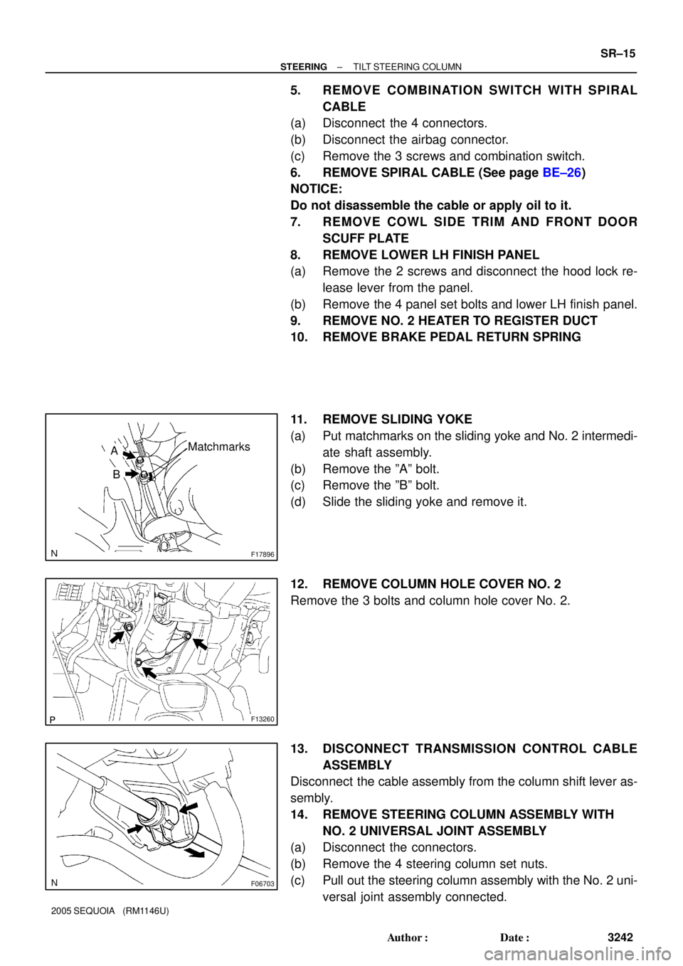
11. REMOVE SLIDING YOKE
(a) Put matchmarks on the sliding yoke and No. 2 intermedi-
ate shaft assembly.
(b) Remove the ºAº bolt.
(c) Remove the ºBº bolt.
(d) Slide the sliding yoke and remove it.
12. REMOVE COLUMN HOLE COVER NO. 2
Remove the 3 bolts and column hole cover No. 2.
13. DISCONNECT TRANSMISSION CONTROL CABLE
ASSEMBLY
Disconnect the cable assembly from the column shift lever as-
sembly.
14. REMOVE STEERING COLUMN ASSEMBLY WITH
NO. 2 UNIVERSAL JOINT ASSEMBLY
(a) Disconnect the connectors.
(b) Remove the 4 steering column set nuts.
(c) Pull out the steering column assembly with the No. 2 uni-
versal joint assembly connected.
Page 3259 of 4323

F13260
F17896
BMatchmarks
A
F19948
Mark
SR±24
± STEERINGTILT STEERING COLUMN
3251 Author�: Date�:
2005 SEQUOIA (RM1146U)
5. INSTALL COLUMN HOLE COVER NO. 2
Install the column hole cover No. 2 to the body with the 3 bolts.
Torque: 8.0 N´m (82 kgf´cm, 71 in.´lbf)
6. INSTALL SLIDING YOKE
(a) Align the matchmark on the sliding yoke with the one on
the No. 2 intermediate shaft assembly.
(b) Install the ºBº bolt.
Torque: 35 N´m (360 kgf´cm, 26 ft´lbf)
(c) Install the ºAº bolt.
Torque: 35 N´m (360 kgf´cm, 26 ft´lbf)
7. INSTALL BRAKE PEDAL RETURN SPRING
8. INSTALL NO. 2 HEATER TO REGISTER DUCT
9. INSTALL LOWER LH FINISH PANEL
(a) Install the lower LH finish panel with the 4 bolts.
(b) Connect the hood lock release lever with the 2 screws.
10. INSTALL COWL SIDE TRIM AND FRONT DOOR
SCUFF PLATE
11. INSTALL SPIRAL CABLE (See page BE±26)
12. INSTALL COMBINATION SWITCH WITH SPIRAL
CABLE
(a) Install the combination switch with the 3 screws.
(b) Connect the airbag connector.
(c) Connect the 4 connectors.
13. INSTALL UPPER AND LOWER COLUMN COVERS
Install the upper and lower column covers with the 3 screws.
14. CENTER SPIRAL CABLE
(a) Check that the front wheels are facing straight ahead.
(b) Turn the cable counterclockwise by hand until it feels firm.
(c) Then rotate the cable clockwise about 2.5 turns to align
the marks.
HINT:
The cable will rotate about 2.5 turns to both the left and right
from the center.