Page 390 of 4323

7 Check for open and")
A21025
Wire Harness Side:
I1
I2
I3I4
I5I6
I7I8
Ignition Coil Connector
B17412
E8
IGF2
IGF1
ECM Connector DI±196
± DIAGNOSTICSENGINE
390 Author�: Date�:
2005 SEQUOIA (RM1146U)
7 Check for open and short in harness and connector between ignition coil and
ECM.
Check the harness and connector between the ignition coil
and the ECM (IGF terminal) connectors:
PREPARATION:
(a) Disconnect the I1, I2, I3, I4, I5, I6, I7 or I8 ignition coil con-
nector.
(b) Disconnect the E8 ECM connector.
CHECK:
Check the resistance between the wire harness side connec-
tors.
OK:
Standard:
Tester ConnectionSpecified Condition
Ignition coil (I1±2) ± IGF1 (E8±24)Below 1 W
Ignition coil (I2±2) ± IGF2 (E8±25)Below 1 W
Ignition coil (I3±2) ± IGF1 (E8±24)Below 1 W
Ignition coil (I4±2) ± IGF2 (E8±25)Below 1 W
Ignition coil (I5±2) ± IGF1 (E8±24)Below 1 W
Ignition coil (I6±2) ± IGF2 (E8±25)Below 1 W
Ignition coil (I7±2) ± IGF1 (E8±24)Below 1 W
Ignition coil (I8±2) ± IGF2 (E8±25)Below 1 W
Ignition coil (I1±2) or IGF1 (E8±24) ±
Body ground10 kW or higher
Ignition coil (I2±2) or IGF2 (E8±25) ±
Body ground10 kW or higher
Ignition coil (I3±2) or IGF1 (E8±24) ±
Body ground10 kW or higher
Ignition coil (I4±2) or IGF2 (E8±25) ±
Body ground10 kW or higher
Ignition coil (I5±2) or IGF1 (E8±24) ±
Body ground10 kW or higher
Ignition coil (I6±2) or IGF2 (E8±25) ±
Body ground10 kW or higher
Ignition coil (I7±2) or IGF1 (E8±24) ±
Body ground10 kW or higher
Ignition coil (I8±2) or IGF2 (E8±25) ±
Body ground10 kW or higher
Page 391 of 4323

A21025
Ignition Coil Connector
I1
I2
I3I4
I5I6
I7I8
Wire Harness Side:
B17412
E8
IGT8 IGT2
IGT4
IGT5IGT6IGT3 IGT7IGT1
ECM Connector
± DIAGNOSTICSENGINE
DI±197
391 Author�: Date�:
2005 SEQUOIA (RM1146U)
Check the harness and connector between the ignition coil
and the ECM (IGT terminal) connectors:
PREPARATION:
(a) Disconnect the I1, I2, I3, I4, I5, I6, I7 or I8 ignition coil con-
nector.
(b) Disconnect the E8 ECM connector.
CHECK:
Check the resistance between the wire harness side connec-
tors.
OK:
Standard:
Tester ConnectionSpecified Condition
Ignition coil (I1±3) ± IGT1 (E8±8)Below 1 W
Ignition coil (I2±3) ± IGT2 (E8±15)Below 1 W
Ignition coil (I3±3) ± IGT3 (E8±11)Below 1 W
Ignition coil (I4±3) ± IGT4 (E8±10)Below 1 W
Ignition coil (I5±3) ± IGT5 (E8±13)Below 1 W
Ignition coil (I6±3) ± IGT6 (E8±12)Below 1 W
Ignition coil (I7±3) ± IGT7 (E8±14)Below 1 W
Ignition coil (I8±3) ± IGT8 (E8±9)Below 1 W
Ignition coil (I1±3) or IGT1 (E8±8) ±
Body ground10 kW or higher
Ignition coil (I2±3) or IGT2 (E8±15) ±
Body ground10 kW or higher
Ignition coil (I3±3) or IGT3 (E8±11) ±
Body ground10 kW or higher
Ignition coil (I4±3) or IGT4 (E8±10) ±
Body ground10 kW or higher
Ignition coil (I5±3) or IGT5 (E8±13) ±
Body ground10 kW or higher
Ignition coil (I6±3) or IGT6 (E8±12) ±
Body ground10 kW or higher
Ignition coil (I7±3) or IGT7 (E8±14) ±
Body ground10 kW or higher
Ignition coil (I8±3) or IGT8 (E8±9) ±
Body ground10 kW or higher
OK Replace ignition coil with igniter, then confirm
that there is no misfire.
NG
Repair or replace harness or connector.
Page 392 of 4323
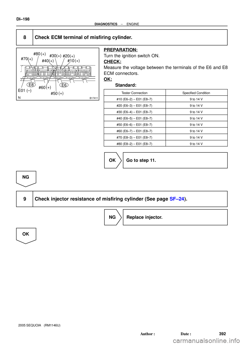
B17411
#80
#70
#60
#50 #30
#20
#10
(+) (+)
(+)
(+)
(+) (+)(+)
#40(+)
E01 (±)
E8E6
DI±198
± DIAGNOSTICSENGINE
392 Author�: Date�:
2005 SEQUOIA (RM1146U)
8 Check ECM terminal of misfiring cylinder.
PREPARATION:
Turn the ignition switch ON.
CHECK:
Measure the voltage between the terminals of the E6 and E8
ECM connectors.
OK:
Standard:
Tester ConnectionSpecified Condition
#10 (E6±2) ± E01 (E8±7)9 to 14 V
#20 (E6±3) ± E01 (E8±7)9 to 14 V
#30 (E6±4) ± E01 (E8±7)9 to 14 V
#40 (E6±5) ± E01 (E8±7)9 to 14 V
#50 (E6±6) ± E01 (E8±7)9 to 14 V
#60 (E6±7) ± E01 (E8±7)9 to 14 V
#70 (E8±3) ± E01 (E8±7)9 to 14 V
#80 (E8±2) ± E01 (E8±7)9 to 14 V
OK Go to step 11.
NG
9 Check injector resistance of misfiring cylinder (See page SF±24).
NG Replace injector.
OK
Page 393 of 4323

10 Check f")
A21343
I9I10
I11I12
I13I14
I15I16
Wire Harness Side:
Injector Connector
B17413
E6
#40
#50#20
#10
#30
#60
#70
#80 E8
± DIAGNOSTICSENGINE
DI±199
393 Author�: Date�:
2005 SEQUOIA (RM1146U)
10 Check for open and short in harness and connector between ignition SW and in-
jector, injector and ECM of misfiring cylinder.
PREPARATION:
(a) Disconnect the I9, I10, I11, I12, I13, I14, I15 or I16 injector
connector.
(b) Disconnect the E6 or E8 ECM connector.
CHECK:
Measure the resistance of the wire harness side connectors be-
tween the ECM and injector.
OK:
Standard:
Tester ConnectionSpecified Condition
Injector (I9±2) ± #10 (E6±2)Below 1 W
Injector (I10±2) ± #20 (E6±3)Below 1 W
Injector (I11±2) ± #30 (E6±4)Below 1 W
Injector (I12±2) ± #40 (E6±5)Below 1 W
Injector (I13±2) ± #50 (E6±6)Below 1 W
Injector (I14±2) ± #60 (E6±7)Below 1 W
Injector (I15±2) ± #70 (E8±3)Below 1 W
Injector (I16±2) ± #80 (E8±2)Below 1 W
Injector (I9±2) or #10 (E6±2) ±
Body ground10 kW or higher
Injector (I10±2) or #20 (E6±3) ±
Body ground10 kW or higher
Injector (I11±2) or #30 (E6±4) ±
Body ground10 kW or higher
Injector (I12±2) or #40 (E6±5) ±
Body ground10 kW or higher
Injector (I13±2) or #50 (E6±6) ±
Body ground10 kW or higher
Injector (I14±2) or #60 (E6±7) ±
Body ground10 kW or higher
Injector (I15±2) or #70 (E8±3) ±
Body ground10 kW or higher
Injector (I16±2) or #80 (E8±2) ±
Body ground10 kW or higher
Page 394 of 4323

A21343
I9I10
I11I12
I13I14
I15I16
Wire Harness Side:
Injector Connector
A21378
I18
Wire Harness Side:
Ignition Switch Connector
IG2
DI±200
± DIAGNOSTICSENGINE
394 Author�: Date�:
2005 SEQUOIA (RM1146U)
PREPARATION:
(a) Disconnect the I9, I10, I11, I12, I13, I14, I15 or I16 injector
connector.
(b) Disconnect the I18 ignition switch connector.
CHECK:
Measure the resistance the wire harness side connectors be-
tween the injector and ignition switch.
OK:
Standard:
Tester ConnectionSpecified Condition
Injector (I9±1) ± IG2 (I18±6)Below 1 W
Injector (I10±1) ± IG2 (I18±6)Below 1 W
Injector (I11±1) ± IG2 (I18±6)Below 1 W
Injector (I12±1) ± IG2 (I18±6)Below 1 W
Injector (I13±1) ± IG2 (I18±6)Below 1 W
Injector (I14±1) ± IG2 (I18±6)Below 1 W
Injector (I15±1) ± IG2 (I18±6)Below 1 W
Injector (I16±1) ± IG2 (I18±6)Below 1 W
Injector (I9±1) or IG2 (I18±6) ±
Body ground10 kW or higher
Injector (I10±1) or IG2 (I18±6) ±
Body ground10 kW or higher
Injector (I11±1) or IG2 (I18±6) ±
Body ground10 kW or higher
Injector (I12±1) or IG2 (I18±6) ±
Body ground10 kW or higher
Injector (I13±1) or IG2 (I18±6) ±
Body ground10 kW or higher
Injector (I14±1) or IG2 (I18±6) ±
Body ground10 kW or higher
Injector (I15±1) or IG2 (I18±6) ±
Body ground10 kW or higher
Injector (I16±1) or IG2 (I18±6) ±
Body ground10 kW or higher
NG Repair or replace harness or connector.
OK
11 Check injector injection of misfiring cylinder (See page SF±29).
NG Replace injector.
OK
Page 395 of 4323
± DIAGNOSTICSENGINE
DI±201
395 Author�: Date�:
2005 SEQUOIA (RM1146U)
12 Check compression pressure of misfiring cylinder (See page EM±3).
NG Repair or replace.
OK
13 Check valve clearance of misfiring cylinder (See page EM±4).
NG Adjust valve clearance.
OK
14 Switch step by number of misfire cylinder (Refer to the result of step 4).
High misfire rate cylinderProceed to
1 or 2 cylindersA
More than 3 cylindersB
B Check for intermittent problems
(See page DI±11).
A
15 Check valve timing (Check for looseness or a jumped tooth of timing belt)
(See page EM±9).
NG Adjust valve timing (Repair or replace timing
belt).
OK
Page 396 of 4323

16 Check fuel pressure (See page SF±7).
NG Check and repair fuel pump, pressure regulator,
fuel pipe line and filter (See pag")
DI±202
± DIAGNOSTICSENGINE
396 Author�: Date�:
2005 SEQUOIA (RM1146U)
16 Check fuel pressure (See page SF±7).
NG Check and repair fuel pump, pressure regulator,
fuel pipe line and filter (See page SF±1).
OK
17 Check intake air temperature and mass air flow rate.
PREPARATION:
(a) Connect the hand±held tester to the DLC3.
(b) Turn the ignition switch ON.
CHECK:
Check the intake air temperature.
(1) When using hand±held tester, enter the following menu: DIAGNOSIS / ENHANCED OBD II /
DATA LIST / ALL / INTAKE AIR.
(2) Read its value displayed on the hand±held tester.
OK:
Equivalent to ambient temperature
CHECK:
Check the air flow rate.
(1) When using hand±held tester, enter the following menu: DIAGNOSIS/ENHANCED OBD II/DATA
LIST/ALL/MAF.
(2) Read its value displayed on the hand±held tester.
OK:
ConditionAir Flow Rate (gm/s)
Ignition switch ON (do not start engine)0
Idling4 to 6
Running without load (2,500 rpm)13 to 20
Idling to quickly acceleratingAir flow rate fluctuates
NG Replace mass air flow meter.
OK
Page 397 of 4323
 (104) (140) (176)(32) (68) (212)
A21042
Ohmmeter
Acceptable
TEMPERATURE �C (�F)
RESISTANCE KW
± DIAGNOSTICSENGINE
DI±203
397 Au")
S01196S01699
30
20
10
5
3
02040 0.11
0.3
0.2 0.52
60 80 100 ±20
(±4) (104) (140) (176)(32) (68) (212)
A21042
Ohmmeter
Acceptable
TEMPERATURE �C (�F)
RESISTANCE KW
± DIAGNOSTICSENGINE
DI±203
397 Author�: Date�:
2005 SEQUOIA (RM1146U)
18 Check engine coolant temperature sensor.
PREPARATION:
Remove the engine coolant temperature sensor.
CHECK:
Measure the resistance between the terminals of the engine
coolant temperature sensor.
Resistance:
Tester ConnectionSpecified Condition
1 ± 22.32 to 2.59 kW (20�C (68�F))
1 ± 20.310 to 0.326 kW (80�C (176�F))
NOTICE:
In case of checking the engine coolant temperature sensor
in the water, be careful not to allow water to go into the ter-
minals. After checking, dry the sensor.
HINT:
Alternate procedure: Connect an ohmmeter to the installed en-
gine coolant temperature sensor and read the resistance. Use
an infrared thermometer to measure the engine temperature in
the immediate vicinity of the sensor. Compare these values to
the resistance/temperature graph. Change the engine temper-
ature (by warming up or cooling down) and repeat the test.
NG Replace
engine coolant temperature sensor.
OK
19 Switch step by number of misfire cylinder (Refer to the result of step 4).
High misfire rate cylinderProceed to
1 or 2 cylindersA
More than 3 cylindersB
B Go to step 5.
A
Check for intermittent problems
(See page DI±11).