Page 2615 of 4323

A04331
A08934
EM±28
± ENGINE MECHANICALTIMING BELT
2607 Author�: Date�:
2005 SEQUOIA (RM1146U)
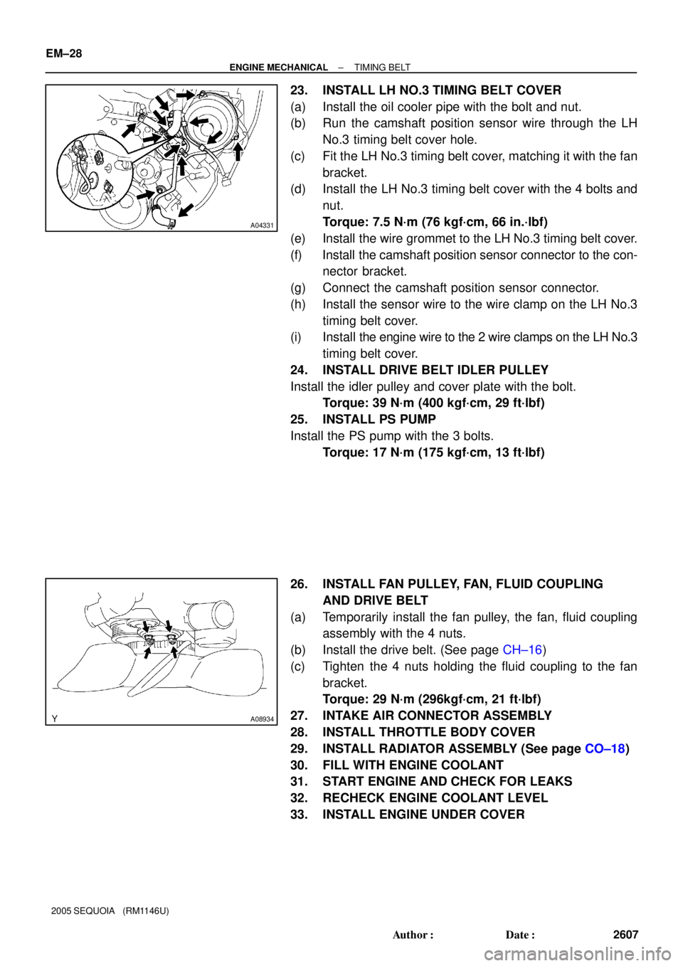
23. INSTALL LH NO.3 TIMING BELT COVER
(a) Install the oil cooler pipe with the bolt and nut.
(b) Run the camshaft position sensor wire through the LH
No.3 timing belt cover hole.
(c) Fit the LH No.3 timing belt cover, matching it with the fan
bracket.
(d) Install the LH No.3 timing belt cover with the 4 bolts and
nut.
Torque: 7.5 N´m (76 kgf´cm, 66 in.´lbf)
(e) Install the wire grommet to the LH No.3 timing belt cover.
(f) Install the camshaft position sensor connector to the con-
nector bracket.
(g) Connect the camshaft position sensor connector.
(h) Install the sensor wire to the wire clamp on the LH No.3
timing belt cover.
(i) Install the engine wire to the 2 wire clamps on the LH No.3
timing belt cover.
24. INSTALL DRIVE BELT IDLER PULLEY
Install the idler pulley and cover plate with the bolt.
Torque: 39 N´m (400 kgf´cm, 29 ft´lbf)
25. INSTALL PS PUMP
Install the PS pump with the 3 bolts.
Torque: 17 N´m (175 kgf´cm, 13 ft´lbf)
26. INSTALL FAN PULLEY, FAN, FLUID COUPLING
AND DRIVE BELT
(a) Temporarily install the fan pulley, the fan, fluid coupling
assembly with the 4 nuts.
(b) Install the drive belt. (See page CH±16)
(c) Tighten the 4 nuts holding the fluid coupling to the fan
bracket.
Torque: 29 N´m (296kgf´cm, 21 ft´lbf)
27. INTAKE AIR CONNECTOR ASSEMBLY
28. INSTALL THROTTLE BODY COVER
29. INSTALL RADIATOR ASSEMBLY (See page CO±18)
30. FILL WITH ENGINE COOLANT
31. START ENGINE AND CHECK FOR LEAKS
32. RECHECK ENGINE COOLANT LEVEL
33. INSTALL ENGINE UNDER COVER
Page 2661 of 4323

A23324
(a)
(b)
(c)
(d)
EM±74
± ENGINE MECHANICALCYLINDER HEAD
2653 Author�: Date�:
2005 SEQUOIA (RM1146U)
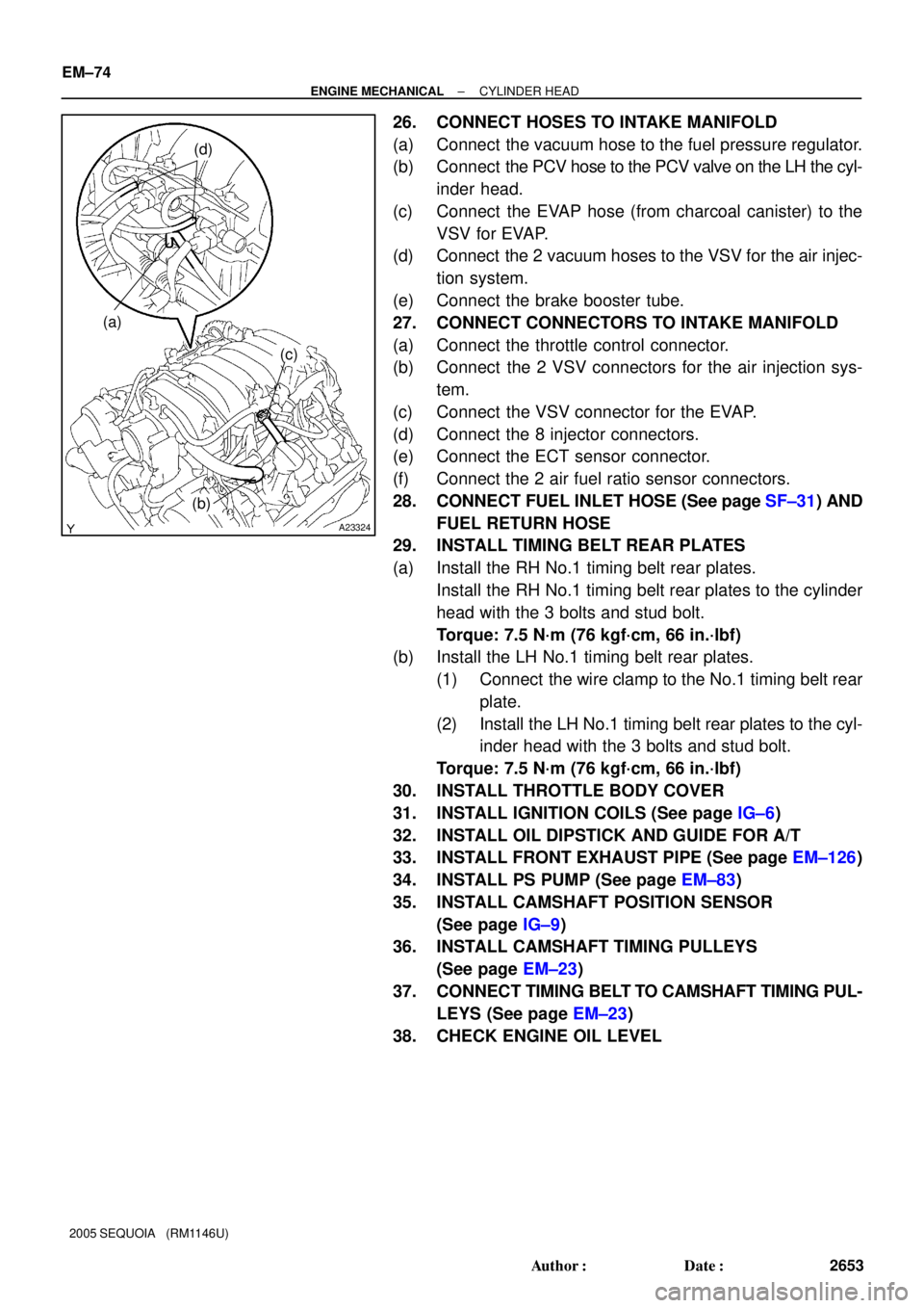
26. CONNECT HOSES TO INTAKE MANIFOLD
(a) Connect the vacuum hose to the fuel pressure regulator.
(b) Connect the PCV hose to the PCV valve on the LH the cyl-
inder head.
(c) Connect the EVAP hose (from charcoal canister) to the
VSV for EVAP.
(d) Connect the 2 vacuum hoses to the VSV for the air injec-
tion system.
(e) Connect the brake booster tube.
27. CONNECT CONNECTORS TO INTAKE MANIFOLD
(a) Connect the throttle control connector.
(b) Connect the 2 VSV connectors for the air injection sys-
tem.
(c) Connect the VSV connector for the EVAP.
(d) Connect the 8 injector connectors.
(e) Connect the ECT sensor connector.
(f) Connect the 2 air fuel ratio sensor connectors.
28. CONNECT FUEL INLET HOSE (See page SF±31) AND
FUEL RETURN HOSE
29. INSTALL TIMING BELT REAR PLATES
(a) Install the RH No.1 timing belt rear plates.
Install the RH No.1 timing belt rear plates to the cylinder
head with the 3 bolts and stud bolt.
Torque: 7.5 N´m (76 kgf´cm, 66 in.´lbf)
(b) Install the LH No.1 timing belt rear plates.
(1) Connect the wire clamp to the No.1 timing belt rear
plate.
(2) Install the LH No.1 timing belt rear plates to the cyl-
inder head with the 3 bolts and stud bolt.
Torque: 7.5 N´m (76 kgf´cm, 66 in.´lbf)
30. INSTALL THROTTLE BODY COVER
31. INSTALL IGNITION COILS (See page IG±6)
32. INSTALL OIL DIPSTICK AND GUIDE FOR A/T
33. INSTALL FRONT EXHAUST PIPE (See page EM±126)
34. INSTALL PS PUMP (See page EM±83)
35. INSTALL CAMSHAFT POSITION SENSOR
(See page IG±9)
36. INSTALL CAMSHAFT TIMING PULLEYS
(See page EM±23)
37. CONNECT TIMING BELT TO CAMSHAFT TIMING PUL-
LEYS (See page EM±23)
38. CHECK ENGINE OIL LEVEL
Page 2674 of 4323

A09152
Connect
± ENGINE MECHANICALENGINE UNIT (2WD)
EM±87
2666 Author�: Date�:
2005 SEQUOIA (RM1146U)
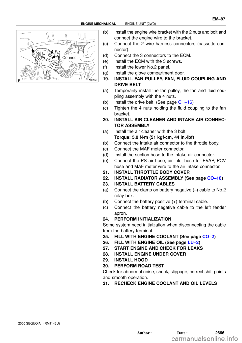
(b) Install the engine wire bracket with the 2 nuts and bolt and
connect the engine wire to the bracket.
(c) Connect the 2 wire harness connectors (cassette con-
nector).
(d) Connect the 3 connectors to the ECM.
(e) Install the ECM with the 3 screws.
(f) Install the lower No.2 panel.
(g) Install the glove compartment door.
19. INSTALL FAN PULLEY, FAN, FLUID COUPLING AND
DRIVE BELT
(a) Temporarily install the fan pulley, the fan and fluid cou-
pling assembly with the 4 nuts.
(b) Install the drive belt. (See page CH±16)
(c) Tighten the 4 nuts holding the fluid coupling to the fan
bracket.
20. INSTALL AIR CLEANER AND INTAKE AIR CONNEC-
TOR ASSEMBLY
(a) Install the air cleaner with the 3 bolt.
Torque: 5.0 N´m (51 kgf´cm, 44 in.´lbf)
(b) Connect the intake air connector to the throttle body.
(c) Connect the MAF meter connector.
(d) Install the suction hose to the intake air connector.
(e) Connect the PS air hose, air inlet hose for EVAP, PCV
hose and MAF meter wire to the air intake connector.
21. INSTALL THROTTLE BODY COVER
22. INSTALL RADIATOR ASSEMBLY (See page CO±18)
23. INSTALL BATTERY CABLES
(a) Connect the clamp on battery negative (±) cable to No.2
relay box.
(b) Connect the battery positive (+) terminal cable.
(c) Connect the battery negative cable to the left fender
apron.
24. PERFORM INITIALIZATION
Some system need initialzation when disconnecting the cable
from the battery terminal.
25. FILL WITH ENGINE COOLANT (See page CO±2)
26. FILL WITH ENGINE OIL (See page LU±2)
27. START ENGINE AND CHECK FOR LEAKS
28. INSTALL ENGINE UNDER COVER
29. INSTALL HOOD
30. PERFORM ROAD TEST
Check for abnormal noise, shock, slippage, correct shift points
and smooth operation.
31. RECHECK ENGINE COOLANT AND OIL LEVELS
Page 2685 of 4323
EM±98
± ENGINE MECHANICALENGINE UNIT (4WD)
2677 Author�: Date�:
2005 SEQUOIA (RM1146U)
22. PERFORM ROAD TEST
Check for abnormal noise, shock, slippage, correct shift points
and smooth operation.
23. RECHECK ENGINE COOLANT AND OIL LEVELS
Page 2825 of 4323

CO0IO±07
± COOLINGCOOLANT
CO±1
2817 Author�: Date�:
2005 SEQUOIA (RM1146U)
COOLANT
INSPECTION
HINT:
Check the coolant level when the engine is cold.
1. CHECK ENGINE COOLANT LEVEL AT RADIATOR RESERVOIR
The engine coolant level should be between the ºLOWº and ºFULLº lines at normal temperature
(20°C(68°F)).
If low, check for leaks and add ºToyota Super Long Life Coolantº or similar high quality ethylene glycol based
non±silicate, non±amine, non±nitrite, and non±borate coolant with long±life hybrid organic acid technology
up to the ºFULLº line.
2. CHECK ENGINE COOLANT QUALITY
(a) Remove the radiator cap.
CAUTION:
To avoid the danger of being burned, do not remove the radiator cap while the engine and radiator
are still hot, as fluid and steam can be blown out under pressure.
(b) There should not be any excessive deposits of rust or scale around the radiator cap or radiator filler
hole, and the coolant should be free from oil.
If excessively dirty, clean the coolant passages and replace the coolant.
(c) Reinstall the radiator cap.
Page 2842 of 4323
CO0UY±03
B07220
CO±18
± COOLINGRADIATOR
2834 Author�: Date�:
2005 SEQUOIA (RM1146U)
INSTALLATION
1. INSTALL NO.1 FAN SHROUD
Install the No.1 fan shroud with the 4 bolts.
Torque: 5.0 N´m (50 kgf´cm, 44 in.´lbf)
2. INSTALL RADIATOR ASSEMBLY
(a) Set the radiator bracket hooks to the radiator support
holes.
(b) Install the 4 bolts.
Torque: 12 N´m (120 N´m, 9 ft´lbf)
3. INSTALL NO.2 FAN SHROUD
Install the No.2 fan shroud with the 2 clips.
4. CONNECT A/T OIL COOLER HOSES TO RADIATOR
5. CONNECT UPPER RADIATOR HOSE TO RADIATOR
6. CONNECT LOWER RADIATOR HOSE TO RADIATOR
7. CONNECT RADIATOR RESERVOIR HOSE TO RADIA-
TOR
8. FILL WITH ENGINE COOLANT
9. START ENGINE AND CHECK FOR ENGINE COOLANT
LEAKS
10. RECHECK ENGINE COOLANT LEVEL
11. INSTALL ENGINE UNDER COVER
Page 2843 of 4323

B16233
Recommended Viscosity (SAE):
TEMPERATURE RANGE ANTICIPATED BEFORE NEXT OIL CHANGE5W±30°C °F
±20
±290
±1820
±740
460
1680
27100
38
LU0GV±05
B07230
Oil Pressure Gauge
Oil Pressure Switch
P08343
Adhesive
± LUBRICATIONOIL AND FILTER
LU±1
2835 Author�: Date�:
2005 SEQUOIA (RM1146U)
OIL AND FILTER
INSPECTION
1. CHECK ENGINE OIL QUALITY
Check the oil for deterioration, entry of water, discoloring or thin-
ning.
If the quality is visibly poor, replace the oil.
Oil grade:
API grade SL Energy±Conserving or ILSAC multi-
grade engine oil.
2. CHECK ENGINE OIL LEVEL
The oil level should be between the ºLº and ºFº marks on the dip-
stick.
If low, check for leakage and add oil up to the ºFº mark.
NOTICE:
Do not fill with engine oil above the ºFº mark.
3. REMOVE ENGINE UNDER COVER
4. REMOVE OIL PRESSURE SWITCH
5. INSTALL OIL PRESSURE GAUGE
6. WARM UP ENGINE
Allow the engine to warm up to normal operating temperature.
7. CHECK OIL PRESSURE
Oil pressure:
At idle29 kPa (0.3 kgf/cm2, 4.2 psi) or more
At 3,000 rpm294 ± 588 kPa (3.0 ± 6.0 kgf/cm2, 43 ± 85 psi)
8. REMOVE OIL PRESSURE GAUGE
9. REINSTALL OIL PRESSURE SWITCH
(a) Apply adhesive to 2 or 3 threads of the oil pressure switch.
Adhesive:
Part No. 08833±00080, THREE BOND 1344, LOCTITE
242 or equivalent
(b) Reinstall the oil pressure switch.
10. START ENGINE, AND CHECK FOR ENGINE OIL
LEAKS
11. REINSTALL ENGINE UNDER COVER
Page 2845 of 4323
B07233
B07234
SST
3/4 Turn
B07235
Front
± LUBRICATIONOIL AND FILTER
LU±3
2837 Author�: Date�:
2005 SEQUOIA (RM1146U)
(d) Tighten the oil filter by hand until the rubber gasket con-
tacts the seat of the filter mounting.
(e) Using SST, give it an additional 3/4 turn to seat the filter.
SST 09228±07501
4. REFILL WITH ENGINE OIL
(a) Clean and install the oil drain plug with a new gasket.
Torque: 39 N´m (400 kgf´cm, 29 ft´lbf)
(b) Fill with fresh engine oil.
Capacity:
Drain and refill w/ Oil filter change
w/o Oil filter change6.2 liters (6.6 Us qts, 5.5 Imp. qts)
5.7 liters (6.0 Us qts, 5.0 Imp. qts)
Dry fill7.1 liters (7.5 Us qts, 6.2 Imp. qts)
(c) Reinstall the oil filler cap.
HINT:
Install the oil filler cap facing the direction as shown in the il-
lustration.
5. START ENGINE AND CHECK FOR ENGINE OIL
LEAKS
6. RECHECK ENGINE OIL LEVEL
7. w/ Oil filter change:
REINSTALL ENGINE UNDER COVER