Page 1053 of 4323
± DIAGNOSTICSTIRE PRESSURE WARNING SYSTEM
DI±851
1045 Author�: Date�:
2005 SEQUOIA (RM1146U)
12 Check DTC (See page DI±820).
CHECK:
Check for a DTC.
OK:
DTC is not output.
NG Replace tire pressure monitor ECU
(See page SA±20).
OK
End
Page 1054 of 4323
DI±852
± DIAGNOSTICSTIRE PRESSURE WARNING SYSTEM
1046 Author�: Date�:
2005 SEQUOIA (RM1146U)
DTC C2171/71 Transmitter ID Not Registered
CIRCUIT DESCRIPTION
This DTC is output when an transmitter ID cannot be registered.
DTC No.DTC Detecting ConditionTrouble Area
C2171/71Transmitter ID code is not registered.
(When an ID code is unregistered for 51 minutes or more.)�Tire pressure monitor ECU
INSPECTION PROCEDURE
NOTICE:
It is necessary to register an ID code after replacing the tire pressure monitor valve sub±assy and/or
the tire pressure monitor ECU (see page DI±805).
HINT:
Set the tire pressure to the specified value.
1 Check tire pressure warning lamp.
PREPARATION:
Turn the ignition switch to the ON position.
CHECK:
Check the tire pressure warning lamp.
RESULT:
Does not blinkA
Comes on and goes off repeatedly at 0.5 second intervalsB
B Registration of transmitter ID
(See page DI±805).
A
2 Clear DTC (See page DI±820).
NEXT
DIDKB±01
Page 1055 of 4323
± DIAGNOSTICSTIRE PRESSURE WARNING SYSTEM
DI±853
1047 Author�: Date�:
2005 SEQUOIA (RM1146U)
3 Check DTC (See page DI±820).
CHECK:
Check for a DTC.
OK:
DTC C2171/71 is not output.
NG Replace tire pressure monitor ECU
(See page SA±20).
OK
4 Confirm that ID registration is complete.
PREPARATION:
Perform the ºCONFIRMATION OF TRANSMITTER ID REGISTRATIONº procedure.
(Refer to step 4 of REGISTRATION on page DI±805).
CHECK:
Confirm that the transmitter ID is registered.
NEXT
End
Page 1056 of 4323
DI±854
± DIAGNOSTICSTIRE PRESSURE WARNING SYSTEM
1048 Author�: Date�:
2005 SEQUOIA (RM1146U)
DTC C2176/76 Receiver error
CIRCUIT DESCRIPTION
This DTC is output when signals from the tire pressure monitor receiver stop.
DTC No.DTC Detecting ConditionTrouble Area
C2176/76
DTC is stored when either of the following is detected:
�Malfunction in tire pressure monitor ECU internal circuit.
�Terminal RF5V is shorted to ground.�Tire pressure monitor receiver assy
�Tire pressure monitor ECU
�Wire harness
DIDKC±01
Page 1057 of 4323
F19172
Tire Pressure
Monitor ECU
IG
GND T17
11 Sub J/B No. 3
B±R
1FI18
Ignition SW
2
AM1 4
BatteryT172
8
3A
AA J37
J/C
B±R
IG11 Instrument Panel J/B
ECU±IG
12T17 T17T17
GND2 RDA
RF5V
GNDRDA+5V
1
45 T19 Tire Pressure
Monitor Receiver
BR±RVL
BD2 BD2 BD2
5
B±R
W±L8
7
16 J30H
J30I
J30JJ29A
J29B
J29C
BR±RVL
BR±RVL
8
3C
1C4
B±Y
1L1Instrument Panel J/B
AM1
1C6
W
ALT F10
Fusible Link BlockInstrument Panel J/B
1F10
1H1
W±B W±B
A
J8
J/C
IE 4 3J/C
5 8
B
± DIAGNOSTICSTIRE PRESSURE WARNING SYSTEM
DI±855
1049 Author�: Date�:
2005 SEQUOIA (RM1146U)
WIRING DIAGRAM
Page 1058 of 4323
F19137
Tire Pressure Monitor Receiver Assy:
T19
+5V
GND
DI±856
± DIAGNOSTICSTIRE PRESSURE WARNING SYSTEM
1050 Author�: Date�:
2005 SEQUOIA (RM1146U)
INSPECTION PROCEDURE
NOTICE:
It is necessary to register an ID code after replacing the tire pressure monitor valve sub±assy and/or
the tire pressure monitor ECU (see page DI±805).
HINT:
Set the tire pressure to the specified value.
1 Inspect tire pressure monitor receiver assy.
PREPARATION:
(a) Disconnect the tire pressure monitor receiver assy T19
connector.
(b) Turn the ignition switch to the ON position.
CHECK:
Measure the voltage according to the value(s) in the table be-
low.
OK:
Tester ConnectionConditionSpecified Condition
T19±4 (GND) ±
T19±5 (+5V)Ignition Switch ON4.5 to 5.5 V
NG Go to step 3.
OK
Page 1059 of 4323
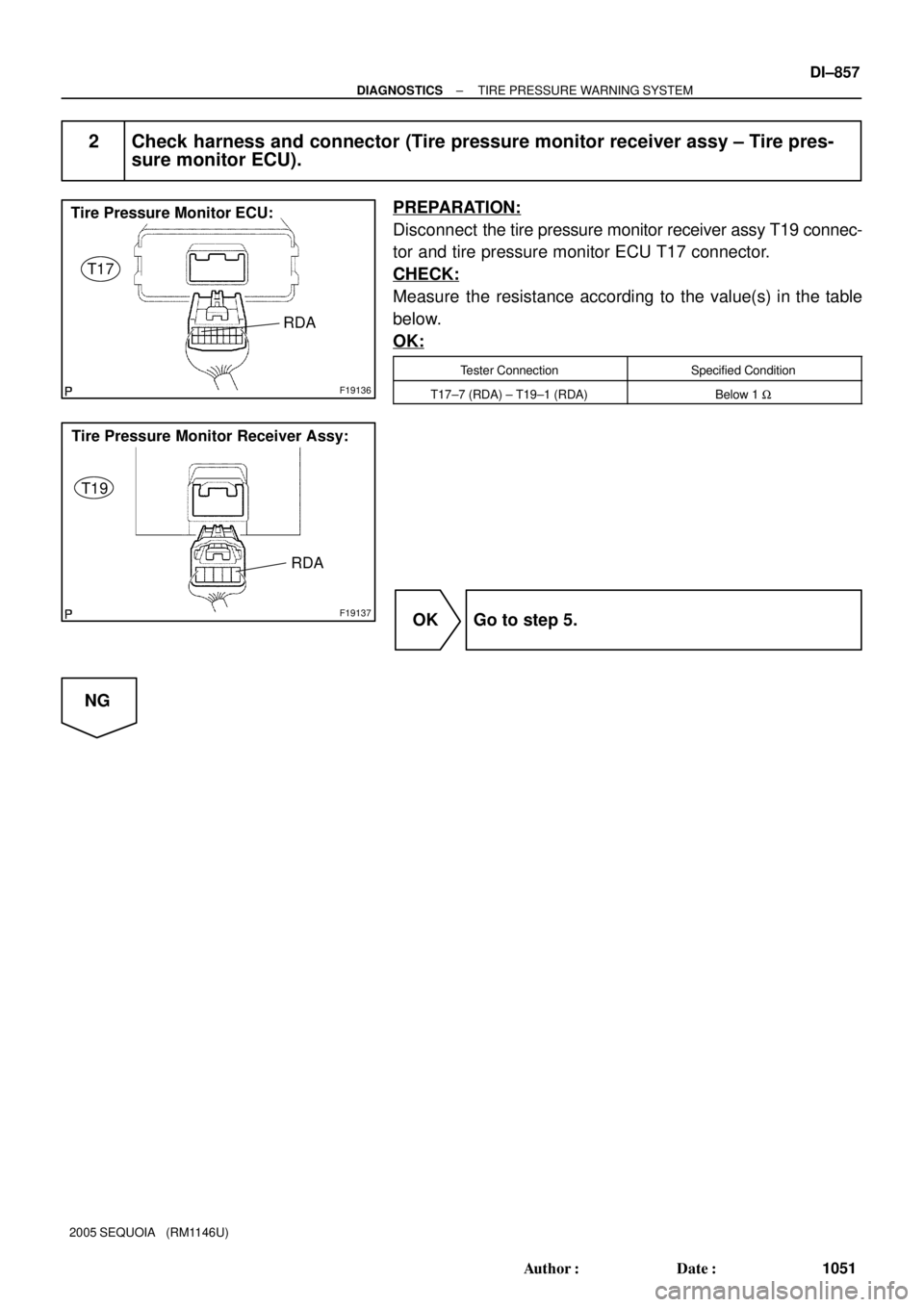
F19136
Tire Pressure Monitor ECU:
T17
RDA
F19137
Tire Pressure Monitor Receiver Assy:
T19
RDA
± DIAGNOSTICSTIRE PRESSURE WARNING SYSTEM
DI±857
1051 Author�: Date�:
2005 SEQUOIA (RM1146U)
2 Check harness and connector (Tire pressure monitor receiver assy ± Tire pres-
sure monitor ECU).
PREPARATION:
Disconnect the tire pressure monitor receiver assy T19 connec-
tor and tire pressure monitor ECU T17 connector.
CHECK:
Measure the resistance according to the value(s) in the table
below.
OK:
Tester ConnectionSpecified Condition
T17±7 (RDA) ± T19±1 (RDA)Below 1 W
OK Go to step 5.
NG
Page 1060 of 4323

F19136
Tire Pressure Monitor ECU:
T17
RF5V
GND2RDA
F19137
Tire Pressure Monitor Receiver Assy:
T19
+5V
GNDRDA
DI±858
± DIAGNOSTICSTIRE PRESSURE WARNING SYSTEM
1052 Author�: Date�:
2005 SEQUOIA (RM1146U)
3 Check harness and connector (Tire pressure monitor receiver assy ± Tire pres-
sure monitor ECU).
PREPARATION:
Disconnect the tire pressure monitor receiver assy T19 connec-
tor and tire pressure monitor ECU T17 connector.
CHECK:
Measure the resistance according to the value(s) in the table
below.
OK:
Tester ConnectionSpecified Condition
T17±7 (RDA) ± T19±1 (RDA)Below 1 W
T17±8 (RF5V) ± T19±5 (+5V)Below 1 W
T17±16 (GND2) ± T19±4 (GND)Below 1 W
T17±7 (RDA) ± Body ground10 kW or higher
T17±8 (RF5V) ± Body ground10 kW or higher
T17±16 (GND2) ± Body ground10 kW or higher
NG Repair or replace harness or connector.
OK
4 Check power source circuit (See page DI±878).
NG Repair or replace power source circuit.
OK
5 Replace tire pressure monitor receiver assy (See page SA±13).
HINT:
Perform the inspection using parts from a normal vehicle when possible.
NEXT