Page 339 of 4323
± DIAGNOSTICSENGINE
DI±145
339 Author�: Date�:
2005 SEQUOIA (RM1146U)
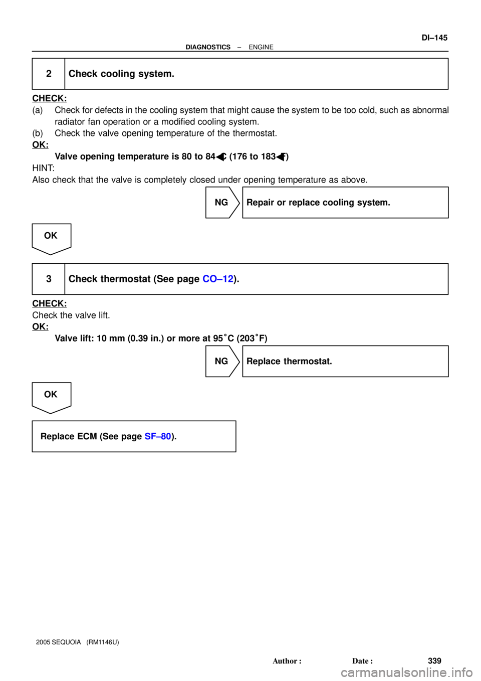
2 Check cooling system.
CHECK:
(a) Check for defects in the cooling system that might cause the system to be too cold, such as abnormal
radiator fan operation or a modified cooling system.
(b) Check the valve opening temperature of the thermostat.
OK:
Valve opening temperature is 80 to 84�C (176 to 183�F)
HINT:
Also check that the valve is completely closed under opening temperature as above.
NG Repair or replace cooling system.
OK
3 Check thermostat (See page CO±12).
CHECK:
Check the valve lift.
OK:
Valve lift: 10 mm (0.39 in.) or more at 95°C (203°F)
NG Replace thermostat.
OK
Replace ECM (See page SF±80).
Page 2501 of 4323
DIDKN±01
I28851
R/B No. 2
� Heater Main Relay
(Marking: HTR)
Compressor
Condenser
Receiver Pressure Switch
Integration Panel Assembly
� A/C ECU
� A/C Switch
� Air Inlet Selector
Heater Unit
� Heater Radiator
� Air Mix Servomotor
� Air Outlet Servomotor
Cooling Unit
� Blower Motor Linear
Controller
� Evaporator
� Expansion Valve
� ThermistorBlower Unit
� Blower Motor
� Air Inlet Servomotor
Water Valve
Rear Heater
Control Assembly
Condenser Fan
Ambient
Temperature
Sensor
Solar Sensor
Room
Temperature
Sensor
Rear Room Temperature
± DIAGNOSTICSAIR CONDITIONING SYSTEM
DI±2299
2493 Author�: Date�:
2005 SEQUOIA (RM1146U)
LOCATION
Page 2502 of 4323
I21419
Water Valve
Air Outlet
Servomotor
Heater Radiator
Thermistor
Evaporator
Expansion Valve Power Transistor Blower Motor
DI±2300
± DIAGNOSTICSAIR CONDITIONING SYSTEM
2494 Author�: Date�:
2005 SEQUOIA (RM1146U)
Page 2506 of 4323

PROBLEM SYMPTOMS TABLE
Front A/C:
SymptomSuspected AreaSee page
Whole functions of the A/C system")
DI3F3±10
DI±2304
± DIAGNOSTICSAIR CONDITIONING SYSTEM
2498 Author�: Date�:
2005 SEQUOIA (RM1146U)
PROBLEM SYMPTOMS TABLE
Front A/C:
SymptomSuspected AreaSee page
Whole functions of the A/C system do not operate4. Integration control and panel
5. IG power source circuitIN±35
DI±2363
Air Flow Control: No blower operation
1. IG power source circuit
2. Heater main relay
3. Blower motor circuit
4. Integration control and panel
5. Blower motor controllerDI±2363
AC±95
DI±2374
IN±35
AC±83
Air Flow Control: No blower control
1. Blower motor circuit
2. Integration control and panel
3. Solar sensor circuit
4. Blower motor controllerDI±2374
IN±35
DI±2336
AC±83
Air Flow Control: Insufficient air flow1. Blower motor circuitDI±2374
Temperature Control: No cool air comes out
1. Refrigerant volume
2. Drive belt tension
3. Refrigeration system inspection with manifold gauge set
4. Compressor circuit
5. Pressure switch circuit
6. Front air mix damper position sensor circuit
7. Front air mix damper control servomotor circuit
8. Front room temp. sensor circuit
9. Ambient temp. sensor circuit
10.Vehicle speed signal circuit
11. Integration control and panelAC±23
AC±15
AC±3
DI±2381
DI±2342
DI±2346
DI±2355
DI±2319
DI±2322
DI±2370
IN±35
Temperature Control: No warm air comes out
1. Front air mix damper position sensor circuit
2. Front air mix damper control servomotor circuit
3. Front room temp. sensor circuit
4. Ambient temp. sensor circuit
5. Vehicle speed signal circuit
6. Front evaporator temp. sensor circuit
7. Integration control and panelDI±2346
DI±2355
DI±2319
DI±2322
DI±2370
DI±2325
IN±35
Temperature Control: Output air is warmer or cooler than the set
temperature or response is slow
1. Refrigerant volume
2. Drive belt tension
3. Refrigeration system inspection with manifold gauge set
4. Cooling fan system
5. Solar sensor circuit
6. Front room temp. sensor circuit
7. Ambient temp. sensor circuit
8. Vehicle speed signal circuit
9. Front evaporator temp. sensor circuit
10.Front air mix damper position sensor circuit
11. Front air mix damper control servomotor circuit
12.Front air inlet damper position sensor circuit
13.Front air inlet damper control servomotor circuit
14.Condenser
15.Evaporator
16.Heater radiator
17.Expansion valve
18.Integration control and panelAC±23
AC±15
AC±3
AC±96
DI±2336
DI±2319
DI±2322
DI±2370
DI±2325
DI±2346
DI±2355
DI±2349
DI±2358
AC±65
AC±24
AC±35
AC±29
IN±35
Page 2508 of 4323
 Temperature Control: Output air is warmer or cooler than the set
temperature or response is slow
1. Refrige")
DI±2306
± DIAGNOSTICSAIR CONDITIONING SYSTEM
2500 Author�: Date�:
2005 SEQUOIA (RM1146U) Temperature Control: Output air is warmer or cooler than the set
temperature or response is slow
1. Refrigerant volume
2. Drive belt tension
3. Refrigeration system inspection with manifold gauge set
4. Cooling fan system
5. Solar sensor circuit
6. Rear room temp. sensor circuit
7. Ambient temp. sensor circuit
8. Rear evaporator temp. sensor circuit
9. Water valve damper position sensor circuit
10.Water valve damper control servomotor circuit
11. Condenser
12.Evaporator
13.Heater radiator
14.Expansion valve
15.Heater control assembly
16.Integration control and panelAC±23
AC±15
AC±3
AC±96
DI±2336
DI±2333
DI±2322
DI±2330
DI±2352
DI±2361
AC±65
AC±70
AC±45
AC±76
IN±35
IN±35
Temperature Control: No temperature control (only Max. cool or
Max. warm)
1. Rear room temp. sensor circuit
2. Ambient temp. sensor circuit
3. Water valve damper position sensor circuit
4. Water valve damper control servomotor circuit
5. Heater control assembly
6. Integration control and panelDI±2333
DI±2322
DI±2352
DI±2361
IN±35
IN±35
Page 2600 of 4323
EM0KV±13
A19404
PS Air Hose
Intake Air ConnectorRadiator Assembly
N´m (kgf´cm, ft´lbf) : Specified torqueDrive BeltA/C Compressor
Connector
A/T Oil Cooler Hose
Fan and Fluid Coupling
Assembly
Fan Pulley
49 (500, 36)
x 4
29 (296, 21)
Throttle Body Cover
MAF Meter Wire
Engine Under Cover (4WD)2WDEngine Under Cover
PS PumpNo. 2 Fan Shroud
Vacuum Hose
PCV Hose
Clip
17 (175, 13)
12 (122, 9)
A/C Compressor
A/C Suction Hose
17 (175, 13)
x 5
29 (296, 21)
29 (296, 21)
± ENGINE MECHANICALTIMING BELT
EM±13
2592 Author�: Date�:
2005 SEQUOIA (RM1146U)
TIMING BELT
COMPONENTS
Page 2603 of 4323

REMOVAL
1. REMOVE ENGINE UNDER COVER
2. DRAIN ENGINE COOLANT
3. REMOVE RADIATOR ASSE")
EM1WX±01
A08934
A04329
A04331
EM±16
± ENGINE MECHANICALTIMING BELT
2595 Author�: Date�:
2005 SEQUOIA (RM1146U)
REMOVAL
1. REMOVE ENGINE UNDER COVER
2. DRAIN ENGINE COOLANT
3. REMOVE RADIATOR ASSEMBLY (See page CO±17)
4. REMOVE THROTTLE BODY COVER
5. REMOVE INTAKE AIR CONNECTOR ASSEMBLY
6. REMOVE DRIVE BELT, FAN, FLUID COUPLING AND
FAN PULLEY
(a) Loosen the 4 nuts holding the fluid coupling to the fan
bracket.
(b) Remove the drive belt. (See page CH±7)
(c) Remove the 4 nuts, the fan, fluid coupling assembly and
fan pulley.
7. DISCONNECT PS PUMP
Remove the 3 bolts, and disconnect the PS pump from the en-
gine.
HINT:
Suspend the PS pump securely.
8. REMOVE DRIVE BELT IDLER PULLEY
Remove the pulley bolt, cover plate and idler pulley.
9. REMOVE RH NO.3 TIMING BELT COVER
Remove the 3 bolts, nut and RH No.3 timing belt cover.
10. REMOVE LH NO.3 TIMING BELT COVER
(a) Disconnect the engine wire from the 2 wire clamps.
(b) Remove the 4 bolts and nut.
(c) Disconnect the camshaft position sensor wire from the
wire clamp on the LH No.3 timing belt cover.
(d) Disconnect the camshaft position sensor connector from
the connector bracket.
(e) Disconnect the camshaft position sensor connector.
(f) Remove the wire grommet from the LH No.3 timing belt
cover.
Page 2615 of 4323

23. INSTALL LH NO.3 TIMING BELT COVER
(a) Install the oil cooler pipe with the bolt and nut.
(b) Run")
A04331
A08934
EM±28
± ENGINE MECHANICALTIMING BELT
2607 Author�: Date�:
2005 SEQUOIA (RM1146U)
23. INSTALL LH NO.3 TIMING BELT COVER
(a) Install the oil cooler pipe with the bolt and nut.
(b) Run the camshaft position sensor wire through the LH
No.3 timing belt cover hole.
(c) Fit the LH No.3 timing belt cover, matching it with the fan
bracket.
(d) Install the LH No.3 timing belt cover with the 4 bolts and
nut.
Torque: 7.5 N´m (76 kgf´cm, 66 in.´lbf)
(e) Install the wire grommet to the LH No.3 timing belt cover.
(f) Install the camshaft position sensor connector to the con-
nector bracket.
(g) Connect the camshaft position sensor connector.
(h) Install the sensor wire to the wire clamp on the LH No.3
timing belt cover.
(i) Install the engine wire to the 2 wire clamps on the LH No.3
timing belt cover.
24. INSTALL DRIVE BELT IDLER PULLEY
Install the idler pulley and cover plate with the bolt.
Torque: 39 N´m (400 kgf´cm, 29 ft´lbf)
25. INSTALL PS PUMP
Install the PS pump with the 3 bolts.
Torque: 17 N´m (175 kgf´cm, 13 ft´lbf)
26. INSTALL FAN PULLEY, FAN, FLUID COUPLING
AND DRIVE BELT
(a) Temporarily install the fan pulley, the fan, fluid coupling
assembly with the 4 nuts.
(b) Install the drive belt. (See page CH±16)
(c) Tighten the 4 nuts holding the fluid coupling to the fan
bracket.
Torque: 29 N´m (296kgf´cm, 21 ft´lbf)
27. INTAKE AIR CONNECTOR ASSEMBLY
28. INSTALL THROTTLE BODY COVER
29. INSTALL RADIATOR ASSEMBLY (See page CO±18)
30. FILL WITH ENGINE COOLANT
31. START ENGINE AND CHECK FOR LEAKS
32. RECHECK ENGINE COOLANT LEVEL
33. INSTALL ENGINE UNDER COVER


 : Specified torqueDrive BeltA/C Compressor
Connector
A/T Oil Cooler Hose
Fan and Fluid Coupling
Assembly
Fan")