Page 3440 of 4323

6. INSPECT DIMMER RELAY CONTINUITY (w/ Daytime
Running Light)
Condi")
I18559
1
2 34
5
I19450
I19451
BE±28
± BODY ELECTRICALHEADLIGHT AND TAILLIGHT SYSTEM
3432 Author�: Date�:
2005 SEQUOIA (RM1146U)
6. INSPECT DIMMER RELAY CONTINUITY (w/ Daytime
Running Light)
ConditionTester connectionSpecified condition
Constant1 ± 2, 3 ± 4Continuity
Apply B+ between
terminals 1 and 2.3 ± 5Continuity
If continuity is not as specified, replace the relay.
7. AUTO ON:
INSPECT AUTOMATIC LIGHT CONTROL
(a) Turn the ignition switch ON.
(b) Turn the light control switch to AUTO.
(c) Gradually cover the top of the sensor.
(d) Check that the accessory lights and the headlights should
turn ON.
8. AUTO OFF:
INSPECT AUTOMATIC LIGHT CONTROL
(a) Gradually expose the sensor.
(b) Check that the headlights and the accessory lights should
turn OFF.
9. INSPECT LIGHTS±OFF CONDITION
(a) Turn the ignition switch ON.
(b) Lights auto ON:
Gradually cover the top of the sensor.
(c) Check that the lights go off under the following conditions.
(1) Light control switch is OFF.
(2) The area surrounding the sensor gets bright.
(3) After the ignition switch is turned OFF and after 30
sec. from when open doors are all closed.
10. INSPECT LIGHTS±ON CONDITION
(a) Open the driver's door while the ignition switch is OFF.
(b) Turn the light control switch to AUTO leaving the door
open and cover the top of the sensor. Make sure that the
lights go on when the ignition switch is turned ON.
11. ADJUST AUTOMATIC LIGHT CONTROL SENSOR
(See page DI±1684)
Page 3441 of 4323

12. Connector connected:
INSPECT")
I01255
1
2 3 4
From Back Side:
I01254
Wire Harness Side:
4 3 2 1
± BODY ELECTRICALHEADLIGHT AND TAILLIGHT SYSTEM
BE±29
3433 Author�: Date�:
2005 SEQUOIA (RM1146U)
12. Connector connected:
INSPECT AUTOMATIC LIGHT CONTROL SENSOR
CIRCUIT
Connect the wire harness side connector to the sensor and in-
spect wire harness side connector from the back side, as shown
in the table.
HINT:
�Ignition switch ON.
�Light control switch AUTO.
�Vehicle's surroundings are bright.
Tester connectionConditionSpecified condition
3 ± GroundConstantContinuity
1 ± GroundIgnition switch LOCK or ACCNo voltage
1 ± GroundIgnition switch ON9.5 V or more
3 ± 4Vehicle is under the direct sun light.
(Sensor is not covered)5.2 ± 9.0 V
3 ± 4Sensor is coveredBelow 0.8 V
If circuit is as specified, try replacing the sensor with a new one.
If the circuit is not as specified, inspect the circuit connected to
other parts.
13. Connector disconnected:
INSPECT AUTOMATIC LIGHT CONTROL SENSOR
CIRCUIT
Disconnect the connector from the sensor and inspect the con-
nector on the wire harness side, as shown in the table.
Tester connectionConditionSpecified condition
3 ± GroundConstantContinuity
1 ± GroundIgnition switch OFFNo voltage
1 ± GroundIgnition switch ONBattery positive voltage
4 ± GroundIgnition switch LOCK or ACCNo voltage
4 ± GroundIgnition switch ON5.2 ± 9.0 V
If the circuit is not as specified, inspect the circuit connected to
other parts.
Page 3488 of 4323

4. INSPECT BACK DOOR POWER WINDOW PULSE
SENSOR (Usi")
I28582
Back Door ECU:
A
1716
I28583
GND BE±76
± BODY ELECTRICALBACK DOOR POWER WINDOW CONTROL SYSTEM
3480 Author�: Date�:
2005 SEQUOIA (RM1146U)
4. INSPECT BACK DOOR POWER WINDOW PULSE
SENSOR (Using oscilloscope)
(a) Remove the back door ECU with the connectors still con-
nected.
(b) Connect the oscilloscope to terminals A±16 and A±17
and body ground.
(c) Operate the back door power window switch.
(d) Check the signal waveform according to the condition (s)
in the table below.
ItemCondition
Tool setting5V/DIV, 10 ms/DIV
Vehicle conditionIgnition switch ON
OK:
As shown in the illustration
5. INSPECT JAM PROTECTION FUNCTION
NOTICE:
Be careful not to get any part of your body caught when
checking.
HINT:
When performing resetting of the limit switch, do checking after
repeating up and down of the glass with automatic operation.
(a) Confirmation of AUTO up operation:
Confirm that the window will close fully with AUTO up op-
eration.
(b) Checking operation of the jam protection function:
(1) Raise the window with AUTO up operation and
check that the window goes down when it touches
the inserted handle of the hammer.
(2) Confirm that the window will then stop going down
after about 200 mm (7.87 in).
HINT:
When removing the glass, glass guide, regulator, etc. be sure
to perform a check of the jam protection function.
If the jam protection is not functioning properly, adjust the power
window motor switch and pulse switch.
Page 3489 of 4323

ADJUSTMENT
1. RESET (INITIALIZE) POWER WINDOW REGULATOR MOTOR
NOTICE:
Resetting t")
BE2MN±01
± BODY ELECTRICALBACK DOOR POWER WINDOW CONTROL SYSTEM
BE±77
3481 Author�: Date�:
2005 SEQUOIA (RM1146U)
ADJUSTMENT
1. RESET (INITIALIZE) POWER WINDOW REGULATOR MOTOR
NOTICE:
Resetting the power window regulator motor (initializing the pulse sensor) is necessary if: 1) the bat-
tery terminal cable is disconnected; 2) the back door ECU, wire harness, power window regulator
switch, power window regulator assembly and power window regulator motor are replaced or re-
moved/installed; or 3) the P/W fuse is replaced or removed. If resetting is not performed, the master
switch assembly will not be able to operate the AUTO operation function, jam protection function and
remote operation function.
(a) Turn the ignition switch ON.
(b) Open the power window halfway by pressing the power window switch.
(c) Fully pull up on the switch until the power window is fully closed and continue to hold the switch for
at least 1 second.
(d) Check that the AUTO UP/DOWN function operates normally.
If the AUTO UP/DOWN function operates normally, reset operations are complete. If abnormal, follow the
steps (e) to (g) below.
(e) Disconnect the negative battery terminal cable for 10 seconds.
(f) Connect the battery terminal cable.
(g) Perform the steps (a) to (d) again.
Page 3495 of 4323

Disarmed state
Perform any of the following and the system will go on to ºArming preparationº:
� With all the doors, the engine hood and the back door closed, lock all doors with the key.
� With all the doors, the engine hood and the back door closed, lock all doors by the
wireless remote control.
� With all the doors, engine hood and back door locked, open and close any of the doors, the
engine hood or the back door, then close and lock all doors, the engine hood and the back door.
Arming preparation
Perform the following and the system will
go on to ºArmed stateº:
� Let 30 seconds elapse with all the doors,
engine hood and the back door closed and
locked.
Perform any of the following and the system
will return to ºDisarmed stateº:
� Open any of the doors, the engine hood or
the back door .
� Unlock any of the doors or the back door.
� Put the key in the key cylinder.
� Reconnect the battery.
Armed state
Perform any of the following and the system
will return to ºDisarmed stateº:
� Unlock any of the doors or the back door by
the wireless remote control.
� Unlock any of the doors or the back door with
the key.
� Put the key in the key cylinder and turn it ON.
Perform any of the following and the system
will go on to ºAlarm soundingº:
� Open any of the doors or the back door.
� Unlock any of the doors or the back door in
any way other than with a key or by the wireless
remote control.
� Open the engine hood.
� Reconnect the battery.
� When input from the optional glass break sensor
is detected (Dealer option).(Key not inserted in key cylinder.)
Alarm sounding
The vehicle's horn and security horn will sound,
and the hazard, interior, tail and head lights come
on for 60 seconds.
After the alarm has stopped, the system will
return to ºArmed stateº. Perform any of the following and the system
will return to ºDisarmed stateº:
� Unlock any of the doors and the back door by
the wireless remote control.
� Unlock any of the doors or the back door with
the key.
� Put the key in the key cylinder and turn it ON.
± BODY ELECTRICALTHEFT DETERRENT SYSTEM
BE±83
3487 Author�: Date�:
2005 SEQUOIA (RM1146U)
2. ACTIVE ARMING MODE
Page 3502 of 4323
Armed state (during entry delay time)
After alarming time has elapsed,")
I28725
Glass Breakage Sensor:
Volume
BE±90
± BODY ELECTRICALTHEFT DETERRENT SYSTEM
3494 Author�: Date�:
2005 SEQUOIA (RM1146U)Armed state (during entry delay time)
After alarming time has elapsed, the sys-
tem will switch to the armed state
Alarm sounding stateAfter alarming time has elapsed, the sys-
tem will switch to the armed state
7. OPERATE GLASS BREAKAGE SENSOR
HINT:
The glass breakage sensor functions only during the active
arming mode.
(a) If the glass breakage sensor detects that the glass is bro-
ken (1st time), the sensor will set off an alarm for 20 se-
conds (pre±alarm). If the glass breakage sensor detects
that the glass is broken furthermore (at 2nd time), the sen-
sor will set off an alarm for 60 seconds.
HINT:
If the 2nd detection is performed during the pre±alarming time
(20 seconds), the sensor will continuously set off the 2nd alarm.
At this time, the total alarming time of the 1st alarm (pre±alarm)
and 2nd alarm is 60 seconds.
(b) The sensitivity of the glass breakage sensor can be ad-
justed by the volume switch in the glass breakage sensor.
HINT:
Because the glass breakage sensor has a high sensitivity, it
might set off a wrong alarm if the volume switch is adjusted too
high.
Page 3503 of 4323
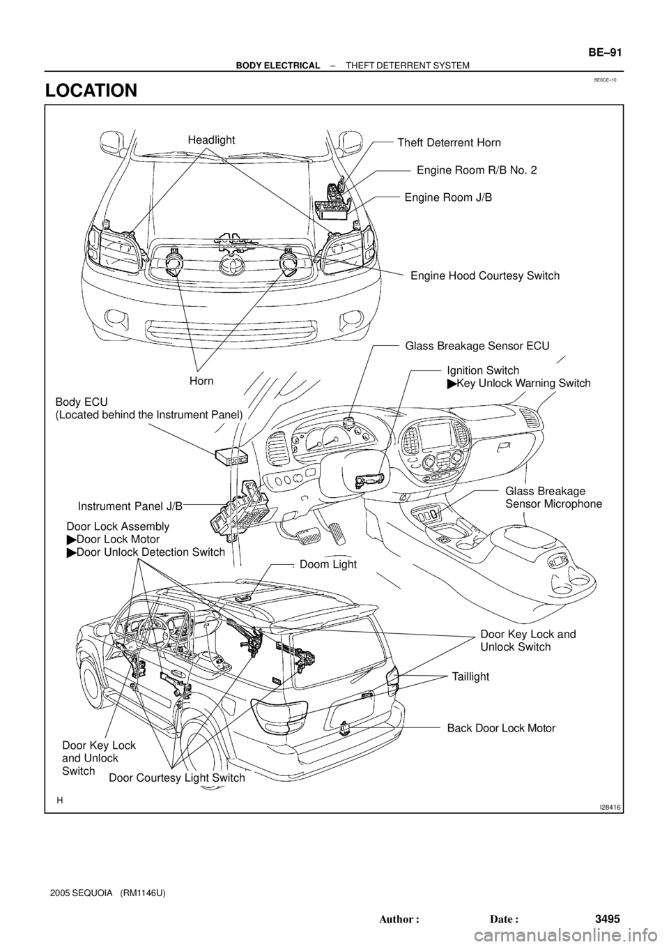
BE0CE±10
I28416
Theft Deterrent Horn
Engine Hood Courtesy Switch Engine Room J/B
Door Lock Assembly
� Door Lock Motor
� Door Unlock Detection Switch
Ignition Switch
� Key Unlock Warning Switch
Instrument Panel J/B
Door Courtesy Light Switch
Horn
Back Door Lock Motor
Door Key Lock
and Unlock
Switch
Door Key Lock and
Unlock Switch Headlight
Doom Light
Taillight
Body ECU
(Located behind the Instrument Panel)
Engine Room R/B No. 2
Glass Breakage Sensor ECU
Glass Breakage
Sensor Microphone
± BODY ELECTRICALTHEFT DETERRENT SYSTEM
BE±91
3495 Author�: Date�:
2005 SEQUOIA (RM1146U)
LOCATION
Page 3534 of 4323
BE2D9±02
I24349
A
76
BE±122
± BODY ELECTRICALELECTRO CHROMIC MIRROR SYSTEM
3526 Author�: Date�:
2005 SEQUOIA (RM1146U)
INSPECTION
INSPECT ELECTRO CHROMIC INNER MIRROR OPERA-
TION
(a) Cover the sensor A so that the sensor does not receive
any light.
(b) Connect the positive (+) lead the battery to terminal 7 and
the negative (±) lead to terminal 6.
(c) Shine an electric light on the mirror, and check that there
is battery positive voltage and mirror surface becomes
bright to dark.
If operation is not as specified, replace the inner mirror.