Page 1348 of 1943

I15499
N2
N3
DI±822
± DIAGNOSTICSNAVIGATION SYSTEM
2001 PRIUS (RM778U)
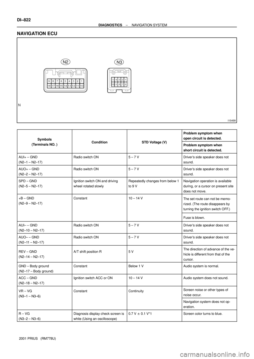
NAVIGATION ECU
SymbolsC ditiSTD V lt (V)
Problem symptom when
open circuit is detected.
Symbols
(Terminals NO. )ConditionSTD Voltage (V)Problem symptom when
short circuit is detected.
AUI+ ± GND
(N2±1 ± N2±17)Radio switch ON5 ± 7 VDriver's side speaker does not
sound.
AUO+ ± GND
(N2±2 ± N2±17)Radio switch ON5 ± 7 VDriver's side speaker does not
sound.
SPD ± GND
(N2±5 ± N2±17)Ignition switch ON and driving
wheel rotated slowlyRepeatedly changes from below 1
to 9 VNavigation operation is available
during, or a cursor on present site
does not move.
+B ± GND
(N2±9 ± N2±17)Constant10 ± 14 VThe set route can not be memo-
rized. (The route disappears by
turning the ignition switch OFF.)
Fuse is blown.
AUI± ± GND
(N2±10 ± N2±17)Radio switch ON5 ± 7 VDriver's side speaker does not
sound.
AUO± ± GND
(N2±11 ± N2±17)Radio switch ON5 ± 7 VDriver's side speaker does not
sound.
REV ± GND
(N2±14 ± N2±17)A/T shift position R5 VThe direction of advance of the ve-
hicle is different from that of the
cursor.
GND ± Body ground
(N2±17 ± Body ground)ConstantBelow 1 VAudio system is normal.
ACC ± GND
(N2±18 ± N2±17)Ignition switch ACC or ON10 ± 14 VAudio system does not sound.
VR ± VG
(N3±1 ± N3±6)
ConstantContinuityScreen noise or other types of
noise occur.
(N3±1 ± N3±6)
Navigation system does not op-
eration.
R ± VG
(N3±2 ± N3±6)Diagnosis display check screen is
white (Using an oscilloscope)0.7 V ± 0.1 V*1Screen color turns to blue.
Page 1349 of 1943

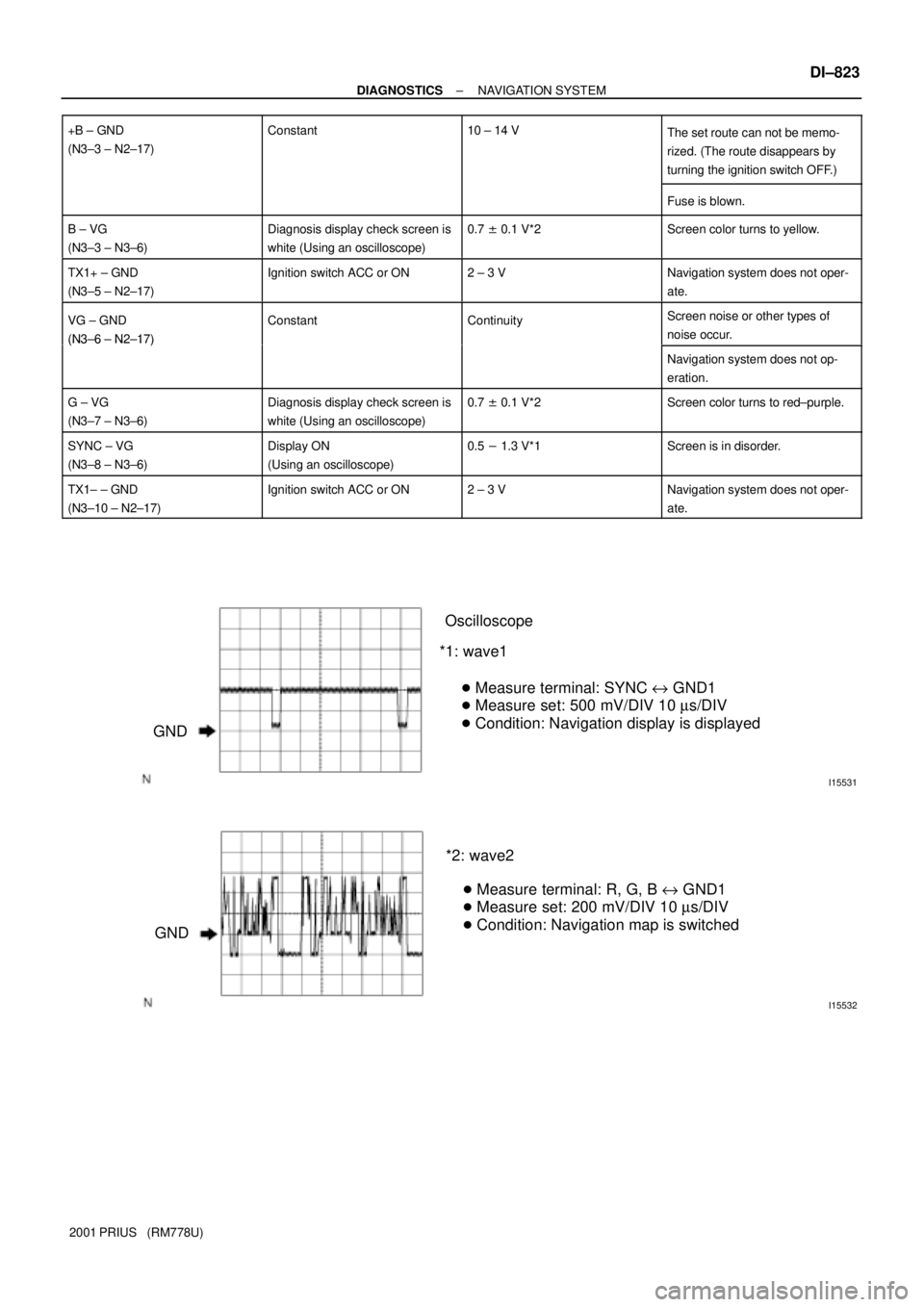
I15531
GNDOscilloscope
*1: wave1
� Measure terminal: SYNC e GND1
� Measure set: 500 mV/DIV 10 ms/DIV
� Condition: Navigation display is displayed
I15532
GND*2: wave2
� Measure terminal: R, G, B e GND1
� Measure set: 200 mV/DIV 10 ms/DIV
� Condition: Navigation map is switched
± DIAGNOSTICSNAVIGATION SYSTEM
DI±823
2001 PRIUS (RM778U) +B ± GND
(N3±3 ± N2±17)
Constant10 ± 14 VThe set route can not be memo-
rized. (The route disappears by
turning the ignition switch OFF.)
Fuse is blown.
B ± VG
(N3±3 ± N3±6)Diagnosis display check screen is
white (Using an oscilloscope)0.7 ± 0.1 V*2Screen color turns to yellow.
TX1+ ± GND
(N3±5 ± N2±17)Ignition switch ACC or ON2 ± 3 VNavigation system does not oper-
ate.
VG ± GND
(N3±6 ± N2±17)
ConstantContinuityScreen noise or other types of
noise occur.
(N3±6 ± N2±17)
Navigation system does not op-
eration.
G ± VG
(N3±7 ± N3±6)Diagnosis display check screen is
white (Using an oscilloscope)0.7 ± 0.1 V*2Screen color turns to red±purple.
SYNC ± VG
(N3±8 ± N3±6)Display ON
(Using an oscilloscope)0.5 - 1.3 V*1Screen is in disorder.
TX1± ± GND
(N3±10 ± N2±17)Ignition switch ACC or ON2 ± 3 VNavigation system does not oper-
ate.
Page 1350 of 1943
± DIAGNOSTICSNAVIGATION SYSTEM
DI±827
2001 PRIUS (RM778U)
3. No navigation screen displayed when ºMAPº, ºMenuº, or ºDESTº
switch pressed. (Screen cannot be switched.)
INSPECTION PROCEDURE
1 Service check mode. (Check the navigation ECU)
NG Troubleshoot for each diagnosis.
OK Go to step 6.
Ncon
2 Check the navigation ECU.
PREPARATION:
Disconnect the navigation ECU connector.
CHECK:
Check voltage terminals +B.
OK:
+B: 10 ± 14 V
CHECK:
Check voltage terminal ACC when turn ignition switch ACC or ON position.
OK:
ACC: 10 ± 14 V
CHECK:
Check continuity terminal GND.
OK:
GND: Continuity
NG Replace or repair wire harness or connector.
OK
DI7OW±01
Page 1351 of 1943
DI±828
± DIAGNOSTICSNAVIGATION SYSTEM
2001 PRIUS (RM778U)
3 Check the navigation ECU.
CHECK:
Check terminal R, G and B.
OK:
R, G, B: See ºNaavigation ECUº of ºTERMINAL OF ECUº.
NG Replace the navigation ECU.
OK
4 Check the multi display.
PREPARATION:
Disconnect the multi display connector.
CHECK:
Check voltage terminals +B.
OK:
+B: 10 ± 14 V
CHECK:
Check voltage terminal ACC when turn ignition switch ACC or ON position.
OK:
ACC: 10 ± 14 V
CHECK:
Check continuity terminal GND.
OK:
GND: Continuity
NG Replace or repair wire harness or connector.
OK
5 Check the multi display.
CHECK:
Check terminal R, G and B.
OK:
R, G, B: See ºmulti displayº of ºTERMINAL OF ECUº.
NG Replace the multi display.
OK
Page 1352 of 1943
± DIAGNOSTICSNAVIGATION SYSTEM
DI±829
2001 PRIUS (RM778U)
Replace the multi display.
6 All of the switches (MAP, Menu, DEST etc.) does not function.
No Replace the center cluster module control.
Ye s
7 Check each switch (A/C switch e.t.c.) of the center cluster module control does
not function.
No Replace the center cluster module control.
Ye s
Replace the multi display.
Page 1353 of 1943
± DIAGNOSTICSNAVIGATION SYSTEM
DI±831
2001 PRIUS (RM778U)
5. No navigation displayed, ºAudio OFFº on audio screen and no
audio sound.
INSPECTION PROCEDURE
1 Service check mode.
NG Troubleshoot for each diagnosis.
OK
2 Check the radio receiver assembly.
PREPARATION:
Disconnect the radio receiver assembly connector.
CHECK:
Check voltage terminals +B.
OK:
+B: 10 ± 14 V
CHECK:
Check voltage terminal ACC when turn ignition switch ACC or ON position.
OK:
ACC: 10 ± 14 V
CHECK:
Check continuity terminal GND.
OK:
GND: Continuity
NG Replace or repair wire harness.
OK
3 Check ºAVC±LAN communication circuitº (See page DI±860).
NG Replace the AVC±LAN circuit or radio receiver
assembly.
OK
DI7OY±01
Page 1354 of 1943
DI±832
± DIAGNOSTICSNAVIGATION SYSTEM
2001 PRIUS (RM778U)
Replace the multi display.
Page 1355 of 1943
± DIAGNOSTICSNAVIGATION SYSTEM
DI±833
2001 PRIUS (RM778U)
6. Screen cannot be dimmed in night time.
INSPECTION PROCEDURE
1 Check if the screen is dimmed at night. (With the light control switch ON), do all
screens except the navigation screen appear in Night Mode?)
NG Check the light control switch.
OK
2 Check the multi display.
CHECK:
Check terminal TAIL.
OK:
TAIL: See ºMulti displayº of ºTERMINAL OF ECUº.
NG Replace or repair wire harness.
OK
3 Check the multi display.
PREPARATION:
Disconnect the multi display connector.
CHECK:
Check voltage terminals +B.
OK:
+B: 10 ± 14 V
CHECK:
Check voltage terminal ACC when turn ignition switch ACC or ON position.
OK:
ACC: 10 ± 14 V
CHECK:
Check continuity terminal GND.
OK:
GND: Continuity
NG Replace or repair wire harness.
DI7OZ±01