Page 252 of 1943

2001 PRIUS (EWD414U)
M OVERALL ELECTRICAL WIRING DIAGRAM
1
234
17 PRIUS
2ACC
IG1
ST1 AM1 4
1
120A MAIN
1B
1D2H 1
5A AM1
2 1
3 52B 3 2D 6
IDCowl si de
panel LH 2K 8
AW±B W±B W± GW
WB±GJ11
JUNCTI ON
CONNECTOR I15
IGNITION SW
100 A DC/ DCBATTERYF18
FUSI BLE L I NK
BLOCK NO. 2
F1 1 F13,
FUSI BL E LI NK
BLOCK NO. 1BD
IG1
RELA Y
10A GAUGE
30A DOOR 7. 5A ECU±B
2C 5 B±Y
9B
AB
AA 2D 81B
1 22C 92L62K312 A
2K 1
W±GSee Interior
Light System
< 10±2> < 10±3>
B
B
W±B W± B
R± GL±B L±B W±B
W± BB 8 B 9,
BODY ECUAB
J24 J25,
JUNCTION
CONNECTORAB
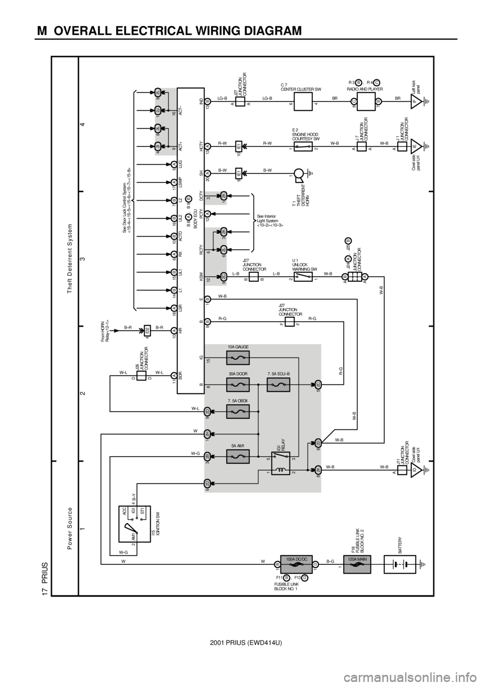
Theft Deterrent System
U 1
UNL OCK
WA RNI NG SW J27
JUNCTI ON
CONNECTOR
12 6 3
Power Source
B 10 A 6 16B 7B 17A 14 B 15 B 18 A
J27
JUNCTION
CONNECTOR
F F 815
W±B2I 42J1 2L 82L9
916
A 20 A13 B13
9IE1 10IE1
IE Co wl s id e
panel LH8C
7B
IFLeft kick
panel 4ID2
10 A
BR
W±B W±BBR LG±B
R± W
B± W B± W R±W LG±B
B±R B±R
W
R±G
R±G
A2A
4 1
A
A6 A
J 1
JUNCTI ON
CONNECTOR J 7
JUNCTI ON
CONNECTORJ27
J UNCTI ON
CONNECTOR Fro m HORN
Relay < 12±1>
RADI O AND PL AYERC B R 3 R 4,
E 2
ENGI NE H OOD
COURTESY SW C 7
CENTE R CLUS TER S W
T 1
THEFT
DETERRENT
HORN1 See Door Lock Control Sys tem
< 15±4> < 15±5> < 15±6> < 15±7> < 15±8>
B IG B E KSW RCTY PCTY DCTY SH HCTY INDHR LSR L1 UL1 RX A CTD UL2 L2 LS WP ACT+ A CT±5A
LUG
W± L
11 A
BDR D D
J26
J UNCTI ON
CONNE CTOR
7. 5A OBDII
2D 9W± L W±L
Page 277 of 1943

NEW MODEL OUTLINE
MAIN EQUIPMENT
182MO23(For U.S.A.)
Glove box Accesory box Multi-box
Front door pocket
Seat back pocket
(Driver's and
passenger seat)
182MO24182MO09
182MO25
Small storage box
Cup holder
(for two caps use)11.839ft3 (by SAE suitcase method)
luggage space is secured.182MO26182MO27182MO28
18
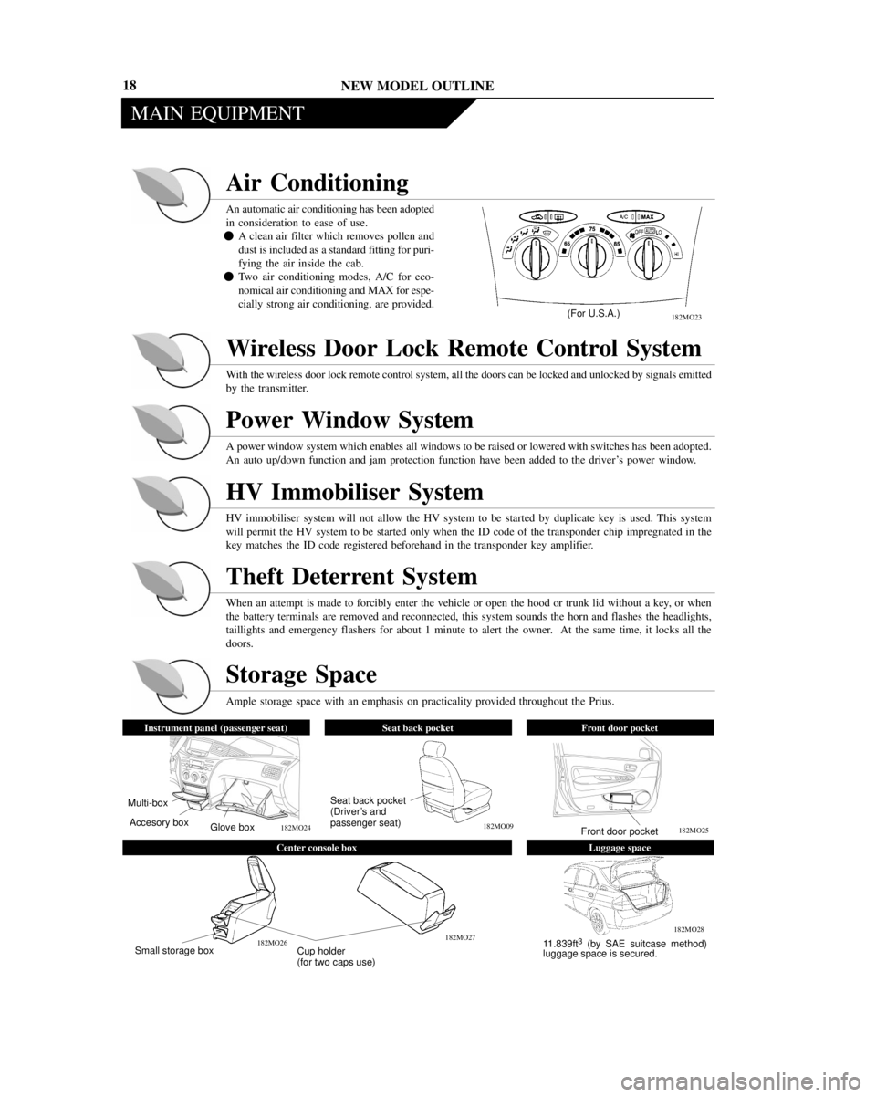
Air Conditioning
An automatic air conditioning has been adopted
in consideration to ease of use.
�A clean air filter which removes pollen and
dust is included as a standard fitting for puri-
fying the air inside the cab.
�Two air conditioning modes, A/C for eco-
nomical air conditioning and MAX for espe-
cially strong air conditioning, are provided.
Wireless Door Lock Remote Control System
With the wireless door lock remote control system, all the doors can be locked and unlocked by signals emitted
by the transmitter.
Power Window System
A power window system which enables all windows to be raised or lowered with switches has been adopted.
An auto up/down function and jam protection function have been added to the driver's power window.
HV Immobiliser System
HV immobiliser system will not allow the HV system to be started by duplicate key is used. This system
will permit the HV system to be started only when the ID code of the transponder chip impregnated in the
key matches the ID code registered beforehand in the transponder key amplifier.
Theft Deterrent System
When an attempt is made to forcibly enter the vehicle or open the hood or trunk lid without a key, or when
the battery terminals are removed and reconnected, this system sounds the horn and flashes the headlights,
taillights and emergency flashers for about 1 minute to alert the owner. At the same time, it locks all the
doors.
Storage Space
Ample storage space with an emphasis on practicality provided throughout the Prius.
Instrument panel (passenger seat)Seat back pocketFront door pocket
Center console boxLuggage space
Page 329 of 1943

THS (TOYOTA HYBRID SYSTEM)
182TH33
31
± REFERENCE ±
The MG1 and the MG2 are generally shut down when the shift lever is in the N position.
However, the shut-down function is canceled under the following exceptions:
�During driving, if the brake pedal is depressed and a wheel locks up, the ABS is activated. After this, low
torque is requested from the MG2 to provide supplemental power in order to restart the rotation of the wheel.
Even if the shift lever is in the N position at this time, the shut-down function is canceled to allow the wheel
to rotate. After the wheel rotation has been restarted, the system resumes its shut-down function.
�When the vehicle is driven in the D or B position and the brake pedal is depressed, the regenerative brake
operates. At this time, as the driver moves the shift lever to the N position, the brake hydraulic pressure in-
creases while the request torque of the regenerative brake decreases gradually so as not to create a sluggish
brake feel. After this, the system effects its shut-down function.
When any of the conditions described below is pres-
ent, the message prompt as shown appears in the
multi information display, accompanied by the illu-
mination of the master warning light and the continu-
ous sounding of the buzzer.
�The ªREADYº light is illuminated, the shift lever
is in the N position, and the HV battery is dis-
charged.
�The ªREADYº light is illuminated, the shift lever
is in the N position, and the driver's door is open.
�The ªREADYº light is illuminated, the parking brake is engaged, the shift lever is in the B or D position, and
the driver's door is open.
Page 404 of 1943

BODY ELECTRICAL ± MULTIPLEX COMMUNICATION SYSTEM 142
�SYSTEM OPERATION
1. General
The ECUs that pertain to the body electrical system perform the functions and system controls described be-
low.
Gateway ECU
�Conversion of data between AVC-LAN and BEAN
�Transmission of vehicle information to the display ECU, in order for it to be displayed on multi-informa-
tion display
Body ECU
�Power window system control (Front, Rear passenger only)
�Door lock control system control
�Wireless door lock remote control system control
�Theft deferrent system control
�Daytime running light system control
�Illuminated entry system control
�Light auto turn-off system control
�Seat belt warning system control
�Key reminder system control
�Diagnosis
Meter ECU
�Meter control
�Illumination and flashing control of indicator and warning lights
�Sounding control of warning buzzer
Air Conditioning ECU
Air Conditioning control
ECM
�Engine control
�Diagnosis
Display ECU
�Transmission and reception associated with audio and visual functions
Page 407 of 1943
BODY ELECTRICAL ± LIGHTING145
�ILLUMINATED ENTRY SYSTEM
�When a door is unlocked through a key operation or transmitter operation, or if a door is opened or closed,
the illuminated entry system turns ON the dome light. If the ignition switch is turned to the ACC or ON
position or if all doors are locked during the 15 seconds in which this light are ON, they will immediately
turn OFF.
�This system is controlled by the body ECU.
�LIGHT AUTO TURN-OFF SYSTEM
�When the ignition key is turned from ON or ACC to LOCK position and the driver's door is opened with
the taillights and headlights on, this system automatically turns them off.
�This system is controlled by the body ECU.
Page 444 of 1943

BODY ELECTRICAL ± ACCESSORIES
182BE40
Power
Window
Master
SwitchUART
Body
ECUFront
Passenger
Switch
Rear LH
Passenger
SwitchRear RH
Passenger
Switch 182
�POWER WINDOW SYSTEM
The power window system has the following features:
�This system includes one-touch auto-up and down and key-off operation function. The one-touch auto up
and down function automatically fully closes and opens the driver's side window. The key-off operation
function makes it possible to operate the power windows for approximately 45 seconds after the ignition
key is turned to the ACC or LOCK position, if the front doors are not opened.
Also, a jam protection function has been adopted to the closing operation of the driver's window. If a for-
eign object becomes jammed in the window during one-touch auto-up or key-off operation of the driver's
window, this function automatically stops the power window and moves it downward.
�This system controls the driver's door through the power window master switch, and the front passenger
and rear passenger doors through the body ECU. The power window master switch and the body ECU
maintain communication through the UART (Universal Asynchronous Receiver Transmitter).
� System Diagram �
Page 445 of 1943

BODY ELECTRICAL ± ACCESSORIES
182BE41
RRP DBody
ECUUARTPower
Window
Master
SwitchDoor Control
Switch (Manual)
Door Control
Switch (Key-linked)
169BE10
Key Unlock
Warning SwitchDoor Courtesy
Switch
Door Lock
MotorsBody
ECU
Serial Data Link
Wireless Door
Control Receiver
Horn
RelayHeadlight
RelayTaillight
RelayTransmitter183
�DOOR LOCK CONTROL SYSTEM
The door lock control system has the following features:
�This system has a ªkey-linked lock and unlockº, ªkey-confine preventionº and ªmanual unlock prohibi-
tionº functions.
�A 2-step unlock function is provided to unlock the driver's door by turning the key cylinder first and to
unlock passenger's door by turning it the second time.
�The control of this system is effected by the body ECU. The door lock control signal from the driver's door
is transmitted from the power window master switch to the body ECU through the UART (Universal
Asynchronous Receiver Transmitter).
�If you unlock using the ignition key from the conditions in which all the doors are locked, the dome light
will be lighted.
� System Diagram �
�WIRELESS DOOR LOCK REMOTE CONTROL SYSTEM
The wireless door lock remote control system has the following features:
�In this system, the wireless door control receiver performs the code identification process and the body
ECU effects the door lock control. Serial data link is provided for communication between the wireless
door control receiver and the body ECU.
�A key-holder type transmitter has been adopted, and it contains the following three switches: the door lock
switch, door unlock switch, and panic switch.
�A rolling code system, in which the signal configuration changes each time when a signal is transmitted
by the transmitter, has been adopted.
�Panic alarm operation has been adopted.
�The verification light function has been adopted. When the transmitter is used to lock or unlock the doors,
this function flashes the taillights to inform that the operation has been completed. However, at the time
of unlocking, the dome light will be lighted.
Page 447 of 1943

BODY ELECTRICAL ± ACCESSORIES
182BE43
DKUL
DKL
LSWD
Power
Window
Master
Switch
Ignition Key SW
From
BatteryIG
LSWP
LSR
KSW
DCTY
PCTY
RCTY
LCTY
HCTY
LUG
Courtesy
Switches
PKL
PKUL
Door Lock Motors
RRP D
Body
ECU
From Battery
Headlight
RelayTaillight
RelayHorn
Relay
HRLY
TRLYTo
HeadlightTo
Taillight
To
Vehicles
Horn
HR
From Battery
Interior
Light
Interior
Light
Relay
Security
Horn
Wireless
Door Control
Receiver
MPX
INDECM
Security
Indicator
185
�THEFT DETERRENT SYSTEM
1. General
�The theft deterrent system uses the door lock control system components and some other parts. When
somebody attempts to forcibly enter the vehicle or open the engine hood or luggage compartment door
without a key, or when the battery terminals are removed and reconnected, the theft deterrent system
sounds the vehicle's horn, security horn and flashes the headlights, taillights, hazard lights and interior
light for about one minute to alert. At the same time, it locks all the doors.
�The control of this system is effected by the body ECU.
� Wiring Diagram �