Page 92 of 1943
2001 PRIUS (EWD414U)
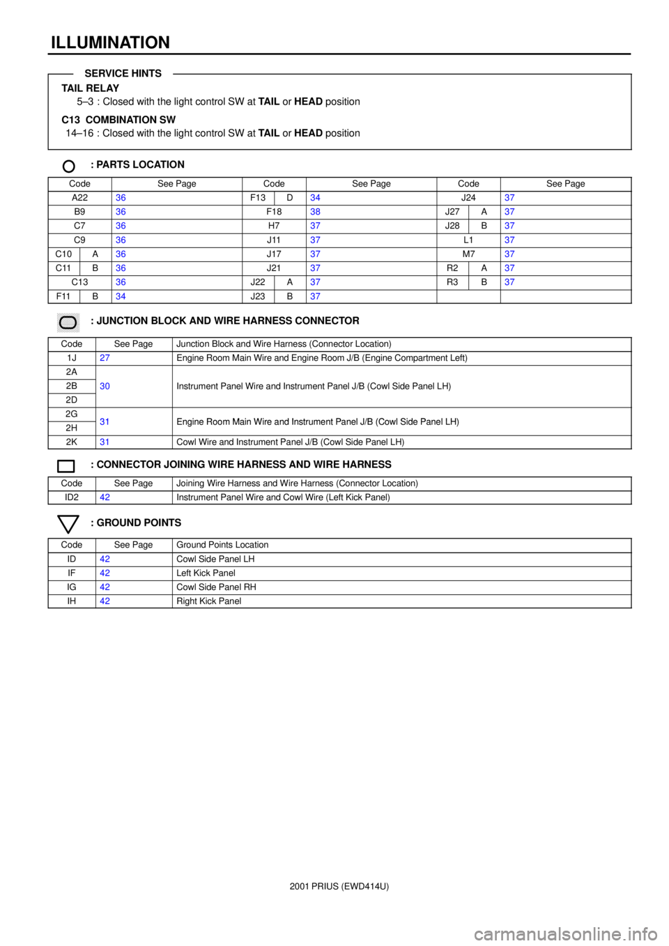
ILLUMINATION
TAIL RELAY
5±3 : Closed with the light control SW at TAIL or HEAD position
C13 COMBINATION SW
14±16 : Closed with the light control SW at TAIL or HEAD position
: PARTS LOCATION
CodeSee PageCodeSee PageCodeSee Page
A2236F13D34J2437
B936F1838J27A37
C736H737J28B37
C936J1137L137
C10A36J1737M737
C11B36J2137R2A37
C1336J22A37R3B37
F11B34J23B37
������ ���: JUNCTION BLOCK AND WIRE HARNESS CONNECTOR
CodeSee PageJunction Block and Wire Harness (Connector Location)
1J27Engine Room Main Wire and Engine Room J/B (Engine Compartment Left)
2A
2B30Instrument Panel Wire and Instrument Panel J/B (Cowl Side Panel LH)
2D
()
2G31Engine Room Main Wire and Instrument Panel J/B (Cowl Side Panel LH)2H31Engine Room Main Wire and Instrument Panel J/B (Cowl Side Panel LH)
2K31Cowl Wire and Instrument Panel J/B (Cowl Side Panel LH)
: CONNECTOR JOINING WIRE HARNESS AND WIRE HARNESS
CodeSee PageJoining Wire Harness and Wire Harness (Connector Location)
ID242Instrument Panel Wire and Cowl Wire (Left Kick Panel)
: GROUND POINTS
CodeSee PageGround Points Location
ID42Cowl Side Panel LH
IF42Left Kick Panel
IG42Cowl Side Panel RH
IH42Right Kick Panel
SERVICE HINTS
Page 94 of 1943
2001 PRIUS (EWD414U)
TURN SIGNAL AND HAZARD WARNING LIGHT
10A
TURN±HAZ FROM POWER SOURCE SYSTEM (
SEE PAGE 50)
1J 610A
GAUGE
2K 10
IA1 6
ID1 4
LH
RH
IG 4 3
A BAB
B B
2 1
2 1
IE 2K 42F32J 12
22 7 6 5C
AA
A AA A
A 133 8 1 4C
AW±B
W±B
G±Y LR E ER EL
R±LW W
R±L
G±R G±R W±B
G± B
G± B G± B W±B W±B W±BG±Y G± Y G± Y
G± YL±B
B
W± B W±BW±B
BIGHAZLL
JUNCTION
CONNECTOR J20
HAZARD SW
[HAZARD WARNING SW] H 7
TURN SIGNAL FLASHER RELAY T 5
IA1 11
G±Y
TURN SIGNAL SW
[COMB. SW] C13
JUNCTION
CONNECTOR J17
JUNCTION
CONNECTOR J 1
JUNCTION
CONNECTOR J 7
FRONT TURN SI GNAL LI GHT RH F 8
FRONT TURN SI GNAL LI GHT LH F 7 JUNCTION
CONNECTOR J18
JUNCTION CONNECTORB J12 A , J13A
AJUNCTION
CONNECTOR J 4
Page 96 of 1943
2001 PRIUS (EWD414U)
TURN SIGNAL AND HAZARD WARNING LIGHT
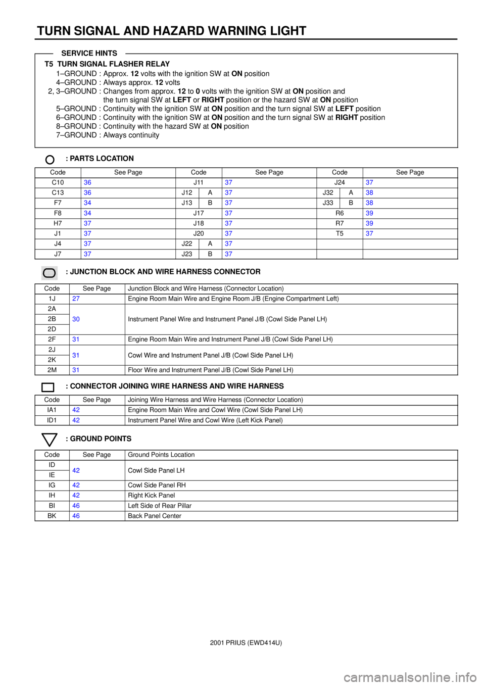
T5 TURN SIGNAL FLASHER RELAY
1±GROUND : Approx. 12 volts with the ignition SW at ON position
4±GROUND : Always approx. 12 volts
2, 3±GROUND : Changes from approx. 12 to 0 volts with the ignition SW at ON position and
the turn signal SW at LEFT or RIGHT position or the hazard SW at ON position
5±GROUND : Continuity with the ignition SW at ON position and the turn signal SW at LEFT position
6±GROUND : Continuity with the ignition SW at ON position and the turn signal SW at RIGHT position
8±GROUND : Continuity with the hazard SW at ON position
7±GROUND : Always continuity
: PARTS LOCATION
CodeSee PageCodeSee PageCodeSee Page
C1036J1137J2437
C1336J12A37J32A38
F734J13B37J33B38
F834J1737R639
H737J1837R739
J137J2037T537
J437J22A37
J737J23B37
������ ���: JUNCTION BLOCK AND WIRE HARNESS CONNECTOR
CodeSee PageJunction Block and Wire Harness (Connector Location)
1J27Engine Room Main Wire and Engine Room J/B (Engine Compartment Left)
2A
2B30Instrument Panel Wire and Instrument Panel J/B (Cowl Side Panel LH)
2D
()
2F31Engine Room Main Wire and Instrument Panel J/B (Cowl Side Panel LH)
2J31Cowl Wire and Instrument Panel J/B (Cowl Side Panel LH)2K31Cowl Wire and Instrument Panel J/B (Cowl Side Panel LH)
2M31Floor Wire and Instrument Panel J/B (Cowl Side Panel LH)
: CONNECTOR JOINING WIRE HARNESS AND WIRE HARNESS
CodeSee PageJoining Wire Harness and Wire Harness (Connector Location)
IA142Engine Room Main Wire and Cowl Wire (Cowl Side Panel LH)
ID142Instrument Panel Wire and Cowl Wire (Left Kick Panel)
: GROUND POINTS
CodeSee PageGround Points Location
ID42Cowl Side Panel LHIE42Cowl Side Panel LH
IG42Cowl Side Panel RH
IH42Right Kick Panel
BI46Left Side of Rear Pillar
BK46Back Panel Center
SERVICE HINTS
Page 100 of 1943
2001 PRIUS (EWD414U)
BACK±UP LIGHT
10A
GAUGE FROM POWER SOURCE SYSTEM (
SEE PAGE 50)
2C 3
52 31
D 13 D14 C19 C184 1
ID 2D 8
2K 8
BI BKB C
A BB BA BAB IF1 9B BA DAD
IJ1 5
4 16
11A E14
A E
A 4 11 15
MPD2MP2+ MPX±
HTE± HTE+
R±B R±BR±B R±BR±LR±L
R±B
W± G
R±B
R±B R±B
R±B W±BR±B W±B
W± B
W±BW± B W±B
W±B
W± BBRYGR± B GR± LGR GR±B
GR
BACK±UP LIGHT
RELAY B 5
NAVIGATION ECU N 2JUNCTION
CONNECTORB J27 A , J28
REV
JUNCTION CONNECTORB J30 A , J31 JUNCTION
CONNECTOR J22
MPX+ MPX+
MPD1RL
MPX2 MPX1 HTE+ HTE±
JUNCTION
CONNECTOR J11
BODY ECU B 8
A/C AMPLIFIER A 7
GATEWAY ECU G 1
JUNCTION
CONNECTOR J24
BACK±UP LIGHT LH
[REAR COMB. LIGHT LH] R 6
BACK±UP LIGHT RH
[REAR COMB. LIGHT RH] R 7 JUNCTION CONNECTORB J32 A , J33
ENGINE CONTROL MODULED E 9 , E10C5 4
5 4
E 14
D 29 D 19
HYBRID VEHICLE
CONTROL ECUD H13 E , H14
IG A
JUNCTION
CONNECTOR
W±B
J17 B
B
(
SHIELDED)
JUNCTION
CONNECTOR J18
A 14
2A 7
2B 6
IH
BR L
L
B 2B3 B 1
COMBINATION
METERB C10 , C11A
PARK/NEUTRAL
POSITION SW P 1
Page 101 of 1943
2001 PRIUS (EWD414U)
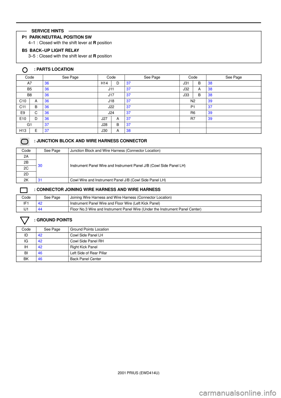
P1 PARK/NEUTRAL POSITION SW
4±1 : Closed with the shift lever at R position
B5 BACK±UP LIGHT RELAY
3±5 : Closed with the shift lever at R position
: PARTS LOCATION
CodeSee PageCodeSee PageCodeSee Page
A736H14D37J31B38
B536J1137J32A38
B836J1737J33B38
C10A36J1837N239
C11B36J2237P137
E9C36J2437R639
E10D36J27A37R739
G137J28B37
H13E37J30A38
������ ���: JUNCTION BLOCK AND WIRE HARNESS CONNECTOR
CodeSee PageJunction Block and Wire Harness (Connector Location)
2A
2B30Instrument Panel Wire and Instrument Panel J/B (Cowl Side Panel LH)2C30Instrument Panel Wire and Instrument Panel J/B (Cowl Side Panel LH)
2D
2K31Cowl Wire and Instrument Panel J/B (Cowl Side Panel LH)
: CONNECTOR JOINING WIRE HARNESS AND WIRE HARNESS
CodeSee PageJoining Wire Harness and Wire Harness (Connector Location)
IF142Instrument Panel Wire and Floor Wire (Left Kick Panel)
IJ144Floor No.3 Wire and Instrument Panel Wire (Under the Instrument Panel Center)
: GROUND POINTS
CodeSee PageGround Points Location
ID42Cowl Side Panel LH
IG42Cowl Side Panel RH
IH42Right Kick Panel
BI46Left Side of Rear Pillar
BK46Back Panel Center
SERVICE HINTS
Page 102 of 1943
2001 PRIUS (EWD414U)
LIGHT AUTO TURN OFF
120A MAIN
1B 1C1
D 11B 1130A
HEAD
1 2
32 41
1F 823 15
7. 5A
TAI L FROM POWER SOURCE SYSTEM (
SEE PAGE 50)
2K 62H 1
B 2B11ID2 2 IA2 6
ID2 3
B 17 B18
IG ID2 5ID262K 1
B F
A D
IB1 3
1
ID 2C 9
B 11 2
B A
A A
2D 8
2K 8 B
16 7
EB 6
E
13 14
AA 17 R±W R±WW
B W B±G
LG LGR±G R±G R±G R±G R±W R
LG±R R
LG±R W±B
R±W R±W R±W
W±B
W± B W±B W±BL±B L±B
L±B
2
(
*1) (
*1) (
*1)
R±W
(
*2)
(
*2)
(
*2) (
*1)H H±LP
TAI L REL AY HEAD RELAYSHORT PIN
JUNCTION
CONNECTOR J20DAYTIME RUNNING
LIGHT RELAY D 3
JUNCTION
CONNECTOR J27
UNLOCK WARNING SW U 1
OFF
TAI L
HEAD
100A DC/DC
FUSIBLE LINK
BLOCK NO. 2 F1 8
FUSIBLE LINK
BLOCK NO. 1C F11 B , F1 2
JUNCTION
CONNECTORB J12 A , J13
JUNCTION CONNECTORB J24 A , J25
DOOR COURTESY
SW FRONT LH D 6
JUNCTION
CONNECTOR J17LIGHT CONTROL SW
[COMB. SW] C13
JUNCTION
CONNECTOR J11
D , F13
BATTERY12
3* 1 : W/ DAYTIME RUNNING LIGHT
* 2 : W/O DAYTIME RUNNING LIGHT (
*1)
(
*2)
(
*2)
(
*1)
7. 5A
ECU±B
2C 5
F
F
B 9
BODY ECUB 9 B
R±G R±G
10A
GAUGE
15
H T DCTY E HRLY TRLY TAIL IG B KSW
Page 103 of 1943
2001 PRIUS (EWD414U)
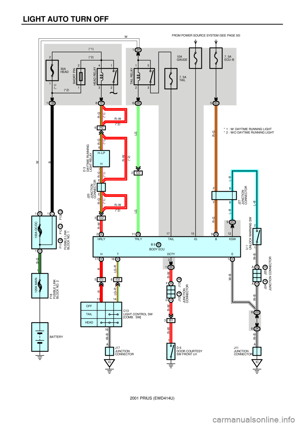
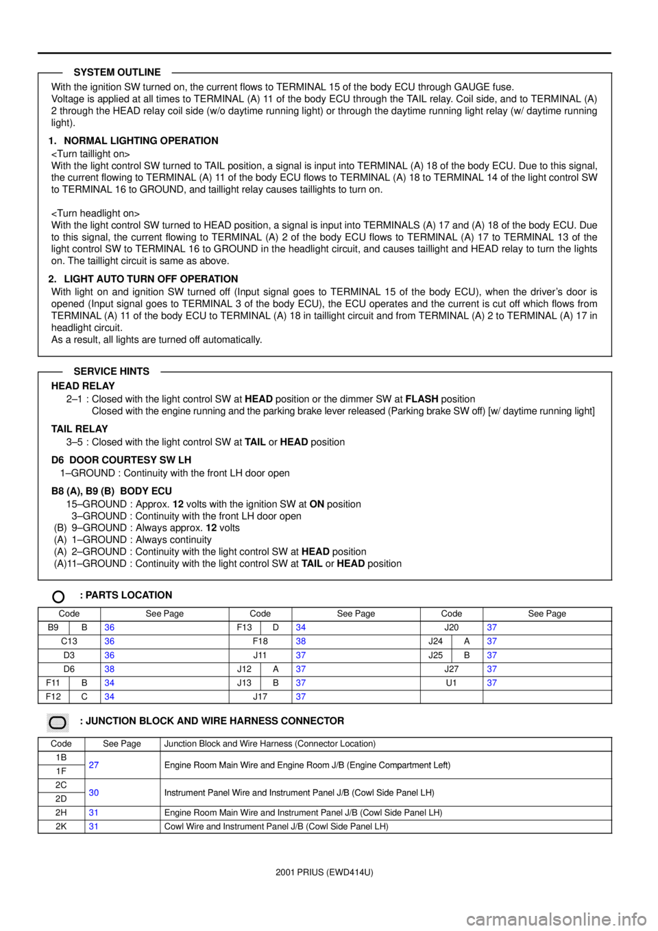
With the ignition SW turned on, the current flows to TERMINAL 15 of the body ECU through GAUGE fuse.
Voltage is applied at all times to TERMINAL (A) 11 of the body ECU through the TAIL relay. Coil side, and to TERMINAL (A)
2 through the HEAD relay coil side (w/o daytime running light) or through the daytime running light relay (w/ daytime running
light).
1. NORMAL LIGHTING OPERATION
With the light control SW turned to TAIL position, a signal is input into TERMINAL (A) 18 of the body ECU. Due to this signal,
the current flowing to TERMINAL (A) 11 of the body ECU flows to TERMINAL (A) 18 to TERMINAL 14 of the light control SW
to TERMINAL 16 to GROUND, and taillight relay causes taillights to turn on.
With the light control SW turned to HEAD position, a signal is input into TERMINALS (A) 17 and (A) 18 of the body ECU. Due
to this signal, the current flowing to TERMINAL (A) 2 of the body ECU flows to TERMINAL (A) 17 to TERMINAL 13 of the
light control SW to TERMINAL 16 to GROUND in the headlight circuit, and causes taillight and HEAD relay to turn the lights
on. The taillight circuit is same as above.
2. LIGHT AUTO TURN OFF OPERATION
With light on and ignition SW turned off (Input signal goes to TERMINAL 15 of the body ECU), when the driver's door is
opened (Input signal goes to TERMINAL 3 of the body ECU), the ECU operates and the current is cut off which flows from
TERMINAL (A) 11 of the body ECU to TERMINAL (A) 18 in taillight circuit and from TERMINAL (A) 2 to TERMINAL (A) 17 in
headlight circuit.
As a result, all lights are turned off automatically.
HEAD RELAY
2±1 : Closed with the light control SW at HEAD position or the dimmer SW at FLASH position
Closed with the engine running and the parking brake lever released (Parking brake SW off) [w/ daytime running light]
TAIL RELAY
3±5 : Closed with the light control SW at TAIL or HEAD position
D6 DOOR COURTESY SW LH
1±GROUND : Continuity with the front LH door open
B8 (A), B9 (B) BODY ECU
15±GROUND : Approx. 12 volts with the ignition SW at ON position
3±GROUND : Continuity with the front LH door open
(B) 9±GROUND : Always approx. 12 volts
(A) 1±GROUND : Always continuity
(A) 2±GROUND : Continuity with the light control SW at HEAD position
(A)11±GROUND : Continuity with the light control SW at TAIL or HEAD position
: PARTS LOCATION
CodeSee PageCodeSee PageCodeSee Page
B9B36F13D34J2037
C1336F1838J24A37
D336J1137J25B37
D638J12A37J2737
F11B34J13B37U137
F12C34J1737
������ ���: JUNCTION BLOCK AND WIRE HARNESS CONNECTOR
CodeSee PageJunction Block and Wire Harness (Connector Location)
1B27Engine Room Main Wire and Engine Room J/B (Engine Compartment Left)1F27Engine Room Main Wire and Engine Room J/B (Engine Compartment Left)
2C30Instrument Panel Wire and Instrument Panel J/B (Cowl Side Panel LH)2D30Instrument Panel Wire and Instrument Panel J/B (Cowl Side Panel LH)
2H31Engine Room Main Wire and Instrument Panel J/B (Cowl Side Panel LH)
2K31Cowl Wire and Instrument Panel J/B (Cowl Side Panel LH)
SYSTEM OUTLINE
SERVICE HINTS
Page 112 of 1943
2001 PRIUS (EWD414U)
KEY REMINDER AND LIGHT REMINDER BUZZER
120A MAIN
1B 1C1
D 11B 1130A
HEAD
1 2
32 41
1F 823 15
7. 5A
TAI L10A
GAUGE FROM POWER SOURCE SYSTEM (
SEE PAGE 50)
2K 62H 1
B 2B11ID2 2 IA2 6
ID2 3
B 17 B18
IG ID2 5ID262K 1
B F
A D
IB1 3
1 16 7
E6
E
13 14
A17 15
T HR±W R±WW
B W B±G
LG LGR±G R±G R±G R±G R±W R
LG±R R
LG±R W±B
R±W R±W R±W
2
(
*1) (
*1) (
*1)
R±W
(
*2)
(
*2)
(
*2) (
*1)H
HRLY TRLYH±LP
TAI L REL AY HEAD RELAYSHORT PIN
JUNCTION
CONNECTOR J20DAYTIME RUNNING
LIGHT RELAY D 3
OFF
TAIL
HEAD
100A DC/DC
FUSIBLE LINK
BLOCK NO. 2 F1 8
FUSIBLE LINK
BLOCK NO. 1C F11 B , F1 2
JUNCTION
CONNECTORB J12 A , J13
DOOR COURTESY
SW FRONT LH D 6
JUNCTION
CONNECTOR J17LIGHT CONTROL SW
[COMB. SW] C13
D , F13
BATTERY3 (
*1)
(
*2)
(
*2)
(
*1)
BODY ECUB B 8 , B 9AL 7. 5A
ECU±B
2C 5 2A 5
R±G
B 9F F
R±G
JUNCTION
CONNECTOR J2 7
DCTYTAIL IG B