Page 342 of 1943
CHASSIS ± P111 HYBRID TRANSAXLE
182CH02
Power Splitting Device
Transaxle
Damper
MG2
Sun Gear
Carrier
Ring GearMG1
Oil Pump
Silent ChainEngine
Counter Gears
Final Gears
182CH03
Coil Spring
Drive force
from the
engine 80
�TRANSAXLE UNIT
1. General
The transaxle unit consists primarily of a transaxle damper, MG (Motor Generator) 1, MG2, power splitting
device and a reduction unit (containing a silent chain, counter gears, and final gears).
2. Transaxle Damper
�A coil-spring type damper with low-twist char-
acteristics has been adopted as the mechanism
to transmit the drive force from the engine.
�A torque fluctuation absorbing mechanism that
uses a dry-type single-plate friction material
has been adopted.
Page 344 of 1943

CHASSIS ± P111 HYBRID TRANSAXLE
182CH77 182CH06
Planetary
Gear UnitRing Gear
Carrier
Sun Gear
MG2
Oil PumpMG1
Transaxle
Damper
Engine
Chain
Counter Gear
Final Gear
MG2
Engine Output Shaft
MG1
182CH08
182CH07
HV Battery
Inverter
MG2 MG1
Engine : Flow of
: motive force
: Flow of
: electrical force
Discharge
Reactive
Control: Torque
: MG2
: Torque
Sun GearCarrier Ring Gear
rpm
MG1 Engine MG2
Nomographic Chart of Planetary
Gear Unit
82
5. Power Splitting Device
General
Planetary gear unit is used for a power splitting device.
As part of the planetary gear unit, the sun gear is connected to MG1, the ring gear is connected to MG2,
and the carrier is connected to the engine output shaft. The motive force is transmitted via the chain to the
counter drive gear.
Item
Connection
Sun GearMG1
Ring GearMG2
CarrierEngine Output Shaft
Operation
1) Starting the Engine
Both while the vehicle is stopped and is in motion, the starting of the engine is performed by MG1. Be-
cause the motive force is transmitted at this time to the ring gear in the planetary gear unit, an electrical
current is applied to MG2 to cancel out the motive force (reactive control).
The nomographic chart below gives a visual representation of the planetary gear's rotational direction,
rotational speed, and power balance. In the nomographic chart, the rpm of the 3 gears maintain a relation-
ship in which they are invariably joined by a direct line.
Page 345 of 1943

CHASSIS ± P111 HYBRID TRANSAXLE
182CH10
182CH09
: Flow of
: motive force
: Flow of
: electrical force
RechargingInverterHV Battery
Reactive
Control
MG2MG1Generate
EngineSun Gear Carrier Ring Gear
rpm
MG1 Engine MG2
: Torque
: MG2
: Torque
Nomographic Chart of Planetary
Gear Unit
Discharge
182CH12
182CH11
Inverter
HV Battery
Discharge
Drive
MG2
MG1
Engine : Flow of
: motive force
: Flow of
: electrical force
Sun Gear Carrier Ring Gear
rpm
MG1Engine
MG2
Nomographic Chart of Planetary
Gear Unit
: Driving
: Load
: MG2
: Torque
83
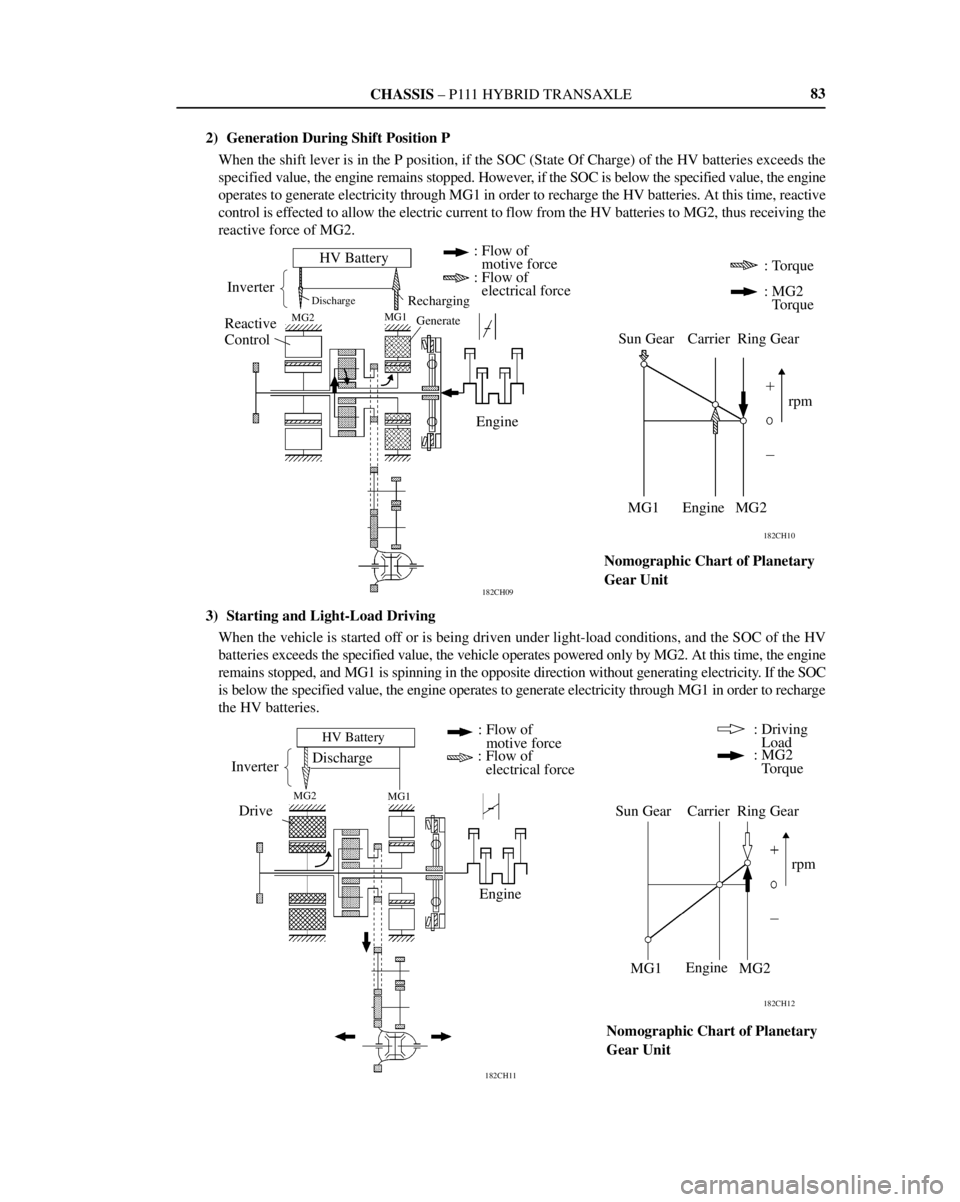
2) Generation During Shift Position P
When the shift lever is in the P position, if the SOC (State Of Charge) of the HV batteries exceeds the
specified value, the engine remains stopped. However, if the SOC is below the specified value, the engine
operates to generate electricity through MG1 in order to recharge the HV batteries. At this time, reactive
control is effected to allow the electric current to flow from the HV batteries to MG2, thus receiving the
reactive force of MG2.
3) Starting and Light-Load Driving
When the vehicle is started off or is being driven under light-load conditions, and the SOC of the HV
batteries exceeds the specified value, the vehicle operates powered only by MG2. At this time, the engine
remains stopped, and MG1 is spinning in the opposite direction without generating electricity. If the SOC
is below the specified value, the engine operates to generate electricity through MG1 in order to recharge
the HV batteries.
Page 346 of 1943

CHASSIS ± P111 HYBRID TRANSAXLE
182CH14
182CH13
HV Battery
Inverter
Drive
MG2 MG1
Discharge
Recharging
Electrical Path
Generation
Engine : Flow of
: motive force
: Flow of
: electrical force
Sun Gear Carrier Ring Gear
rpm
MG1 Engine MG2: Torque
: Driving Load
: MG2 Torque
Nomographic Chart of Planetary
Gear Unit
182CH18
182CH17
Inverter
HV Battery
MG2MG1
Speed
Control
Engine
Recharging
Electrical Path
Generation: Flow of
: electrical force
Sun Gear Carrier Ring Gear
MG1 Engine MG2: Driving
: Load
: MG2
: Torque
Nomographic Chart of Planetary
Gear Unitrpm Speed
Control : Flow of
: motive force 84
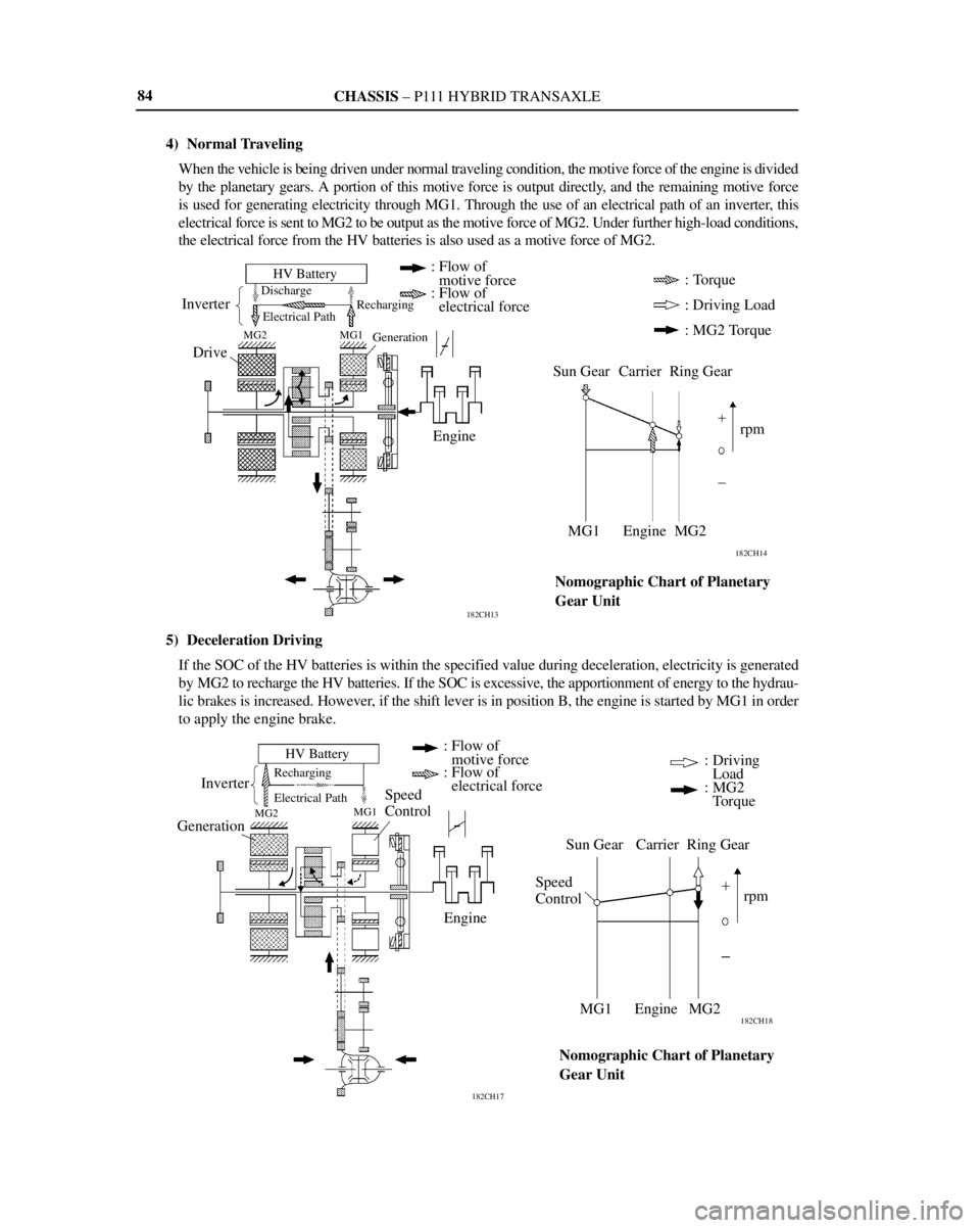
4) Normal Traveling
When the vehicle is being driven under normal traveling condition, the motive force of the engine is divided
by the planetary gears. A portion of this motive force is output directly, and the remaining motive force
is used for generating electricity through MG1. Through the use of an electrical path of an inverter, this
electrical force is sent to MG2 to be output as the motive force of MG2. Under further high-load conditions,
the electrical force from the HV batteries is also used as a motive force of MG2.
5) Deceleration Driving
If the SOC of the HV batteries is within the specified value during deceleration, electricity is generated
by MG2 to recharge the HV batteries. If the SOC is excessive, the apportionment of energy to the hydrau-
lic brakes is increased. However, if the shift lever is in position B, the engine is started by MG1 in order
to apply the engine brake.
Page 347 of 1943

CHASSIS ± P111 HYBRID TRANSAXLE
182CH20
182CH19
Inverter
HV Battery
MG2MG1
Engine
Discharge
Electrical Path
Recharging
GenerationDrive: Flow of
: motive force
: Flow of
: electrical force
Sun Gear Corrier Ring Gear
rpm
MG1 Engine MG2: Driving Load
: MG2 Torque
Nomographic Chart of Planetary
Gear Unit
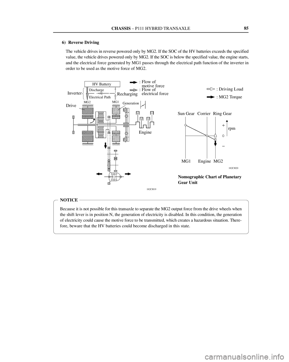
NOTICE
Because it is not possible for this transaxle to separate the MG2 output force from the drive wheels when
the shift lever is in position N, the generation of electricity is disabled. In this condition, the generation
of electricity could cause the motive force to be transmitted, which creates a hazardous situation. There-
fore, beware that the HV batteries could become discharged in this state.85
6) Reverse Driving
The vehicle drives in reverse powered only by MG2. If the SOC of the HV batteries exceeds the specified
value, the vehicle drives powered only by MG2. If the SOC is below the specified value, the engine starts,
and the electrical force generated by MG1 passes through the electrical path function of the inverter in
order to be used as the motive force of MG2.
Page 380 of 1943

CHASSIS ± BRAKES
Battery
Acceptance
Capacity
182CH58
Braking
Force
Regenerative
Braking ForceHydraulic
Braking Force
Vehicle SpeedRegenerative
Braking ForceHydraulic
Braking Force
Time
Changes in Regenerative Braking Force Changes in Braking Force Apportionment
Braking
Force
Driver's DemandDriver's Demand 11 8
2) Regenerative Brake Cooperative Control
a. General
The regenerative brake cooperative control uses the switching valves and linear solenoid valves to regu-
late the hydraulic pressure that is supplied to the wheel cylinders. It also operates cooperatively with
the regenerative braking force that is generated in the MG2 in accordance with the master cylinder pres-
sure.
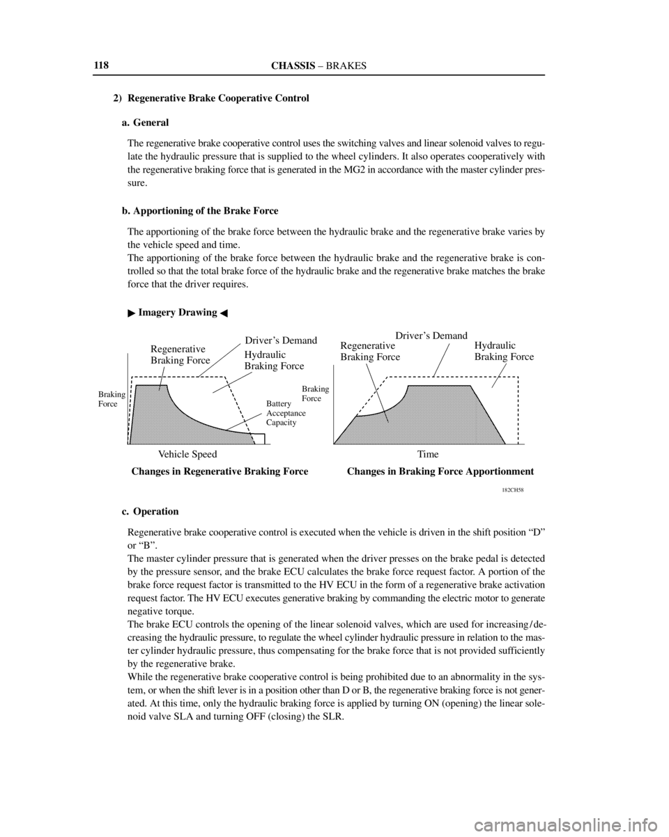
b. Apportioning of the Brake Force
The apportioning of the brake force between the hydraulic brake and the regenerative brake varies by
the vehicle speed and time.
The apportioning of the brake force between the hydraulic brake and the regenerative brake is con-
trolled so that the total brake force of the hydraulic brake and the regenerative brake matches the brake
force that the driver requires.
� Imagery Drawing �
c. Operation
Regenerative brake cooperative control is executed when the vehicle is driven in the shift position ªDº
or ªBº.
The master cylinder pressure that is generated when the driver presses on the brake pedal is detected
by the pressure sensor, and the brake ECU calculates the brake force request factor. A portion of the
brake force request factor is transmitted to the HV ECU in the form of a regenerative brake activation
request factor. The HV ECU executes generative braking by commanding the electric motor to generate
negative torque.
The brake ECU controls the opening of the linear solenoid valves, which are used for increasing / de-
creasing the hydraulic pressure, to regulate the wheel cylinder hydraulic pressure in relation to the mas-
ter cylinder hydraulic pressure, thus compensating for the brake force that is not provided sufficiently
by the regenerative brake.
While the regenerative brake cooperative control is being prohibited due to an abnormality in the sys-
tem, or when the shift lever is in a position other than D or B, the regenerative braking force is not gener-
ated. At this time, only the hydraulic braking force is applied by turning ON (opening) the linear sole-
noid valve SLA and turning OFF (closing) the SLR.
Page 385 of 1943

CHASSIS ± STEERING
182CH68
Rear Wheel
Speed SensorsBrake ECU
Torque Sensor Signal 1
Torque Sensor Signal 2
EMPS
ECUMeter ECU
Gateway ECUDLC3
Display ECU
Multi-information
Display
123
�EMPS (Electric Motor-assisted Power Steering)
1. General
In accordance with sensor information such as that provided by the rear wheel speed sensors, the torque sen-
sor that is mounted on the steering gear, and the EMPS ECU determines the direction and the force of the
power assist and actuates the DC motor that is mounted on the steering gear to provide power assist to the
steering effort.
The EMPS in the Prius the following features:
�This system can provide power assist even when the engine is stopped.
�This system offers excellent fuel economy characteristics because power assist is provided by the DC mo-
tor that is mounted on the steering gear, and this motor consumes energy only when power assist is re-
quired.
�Unlike the conventional hydraulic power steering system, this system excels in serviceability because it
does not require pipes or the power steering fluid.
� System Diagram �
Page 386 of 1943

CHASSIS ± STEERING
182CH69
Meter ECU
EMPS ECU
Relay
DC MotorRear Wheel Speed
Sensors and Rotors
Brake ECU Multi-information Display 124
2. Layout of Main Components
3. Function of Main Components
ComponentsFunction
St i
Torque Sensor
Detects the twist of the torsion bar, converts the torque that is applied
to the torsion bar into an electrical signal, and outputs this signal to
the ECU.
Steering
Gear
DC MotorGenerates power assist in accordance with a signal received from the
EMPS ECU.
Reduction
MechanismReduces the rotation of the DC motor and transmits it to the pinion
shaft.
EMPS ECU
Actuates the DC motor mounted on the steering gear for providing
power assist, based on the signals received from various sensors and
the rear wheel speed signal.
Meter ECUOutputs a signal for displaying the PS warning on the center display
in case of a malfunction in the system.
Brake ECURear wheel speed signals are outputted to EMPS ECU.
RelaySupplies power to the DC motor for power assist.
Multi-information DisplayDisplays the PS warning in case of a malfunction in the system.