Page 1504 of 1943
A12945
No.1 Cam Lobe
A12946
A12943
9
9
96
5
2
1
4
3
8
7 EM±46
± ENGINE MECHANICALCYLINDER HEAD
2001 PRIUS (RM778U)
(g) Connect the upper radiator hose to the water hose
unions.
(h) Connect the heater hose to the water hose unions.
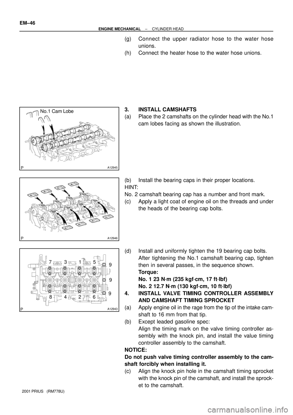
3. INSTALL CAMSHAFTS
(a) Place the 2 camshafts on the cylinder head with the No.1
cam lobes facing as shown the illustration.
(b) Install the bearing caps in their proper locations.
HINT:
No. 2 camshaft bearing cap has a number and front mark.
(c) Apply a light coat of engine oil on the threads and under
the heads of the bearing cap bolts.
(d) Install and uniformly tighten the 19 bearing cap bolts.
After tightening the No.1 camshaft bearing cap, tighten
then in several passes, in the sequence shown.
Torque:
No. 1 23 N´m (235 kgf´cm, 17 ft´lbf)
No. 2 12.7 N´m (130 kgf´cm, 10 ft´lbf)
4. INSTALL VALVE TIMING CONTROLLER ASSEMBLY
AND CAMSHAFT TIMING SPROCKET
(a) Apply engine oil in the rage from the tip of the intake cam-
shaft to 16 mm from that tip.
(b) Except leaded gasoline spec:
Align the timing mark on the valve timing controller as-
sembly with the knock pin, and install the value timing
controller assembly to the camshaft.
NOTICE:
Do not push valve timing controller assembly to the cam-
shaft forcibly when installing it.
(c) Align the knock pin hole in the camshaft timing sprocket
with the knock pin of the camshaft, and install the sprock-
et to the camshaft.
Page 1505 of 1943
A13933
A11226
A13932
± ENGINE MECHANICALCYLINDER HEAD
EM±47
2001 PRIUS (RM778U)
(d) Temporarily install the timing sprocket bolt.
(e) Hold the hexagon head portion of the camshaft with a
wrench, and install the bolt.
Torque: 64 N´m (650 kgf´cm, 47 ft´lbf)
5. CHECK AND ADJUST VALVE CLEARANCE
(See page EM±5)
6. INSTALL CYLINDER HEAD COVER
(See page EM±21)
7. INSTALL OIL CONTROL VALVE
8. INSTALL OIL FILTER CAP
9. INSTALL PCV VALVE
10. INSTALL ECT SENSOR
(See page SF±49)
11. INSTALL CAMSHAFT POSITION SENSOR
(See page IG±10)
12. INSTALL TIMING CHAIN COVER
(See page EM±21)
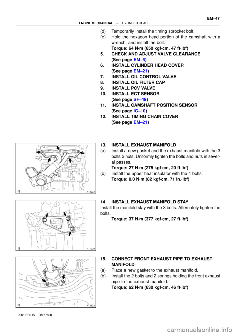
13. INSTALL EXHAUST MANIFOLD
(a) Install a new gasket and the exhaust manifold with the 3
bolts 2 nuts. Uniformly tighten the bolts and nuts in sever-
al passes.
Torque: 27 N´m (275 kgf´cm, 20 ft´lbf)
(b) Install the upper heat insulator with the 4 bolts.
Torque: 8.0 N´m (82 kgf´cm, 71 in.´lbf)
14. INSTALL EXHAUST MANIFOLD STAY
Install the manifold stay with the 3 bolts. Alternately tighten the
bolts.
Torque: 37 N´m (377 kgf´cm, 27 ft´lbf)
15. CONNECT FRONT EXHAUST PIPE TO EXHAUST
MANIFOLD
(a) Place a new gasket to the exhaust manifold.
(b) Install the 2 bolts and 2 springs holding the front exhaust
pipe to the exhaust manifold.
Torque: 62 N´m (630 kgf´cm, 46 ft´lbf)
Page 1506 of 1943
A13935
A13934
A13907
EM±48
± ENGINE MECHANICALCYLINDER HEAD
2001 PRIUS (RM778U)
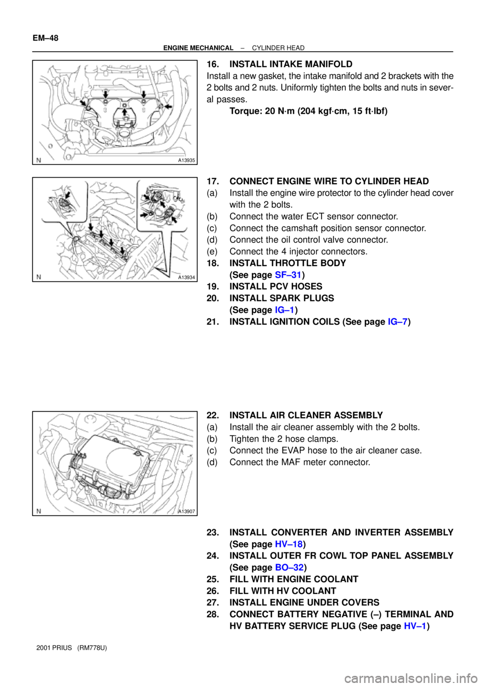
16. INSTALL INTAKE MANIFOLD
Install a new gasket, the intake manifold and 2 brackets with the
2 bolts and 2 nuts. Uniformly tighten the bolts and nuts in sever-
al passes.
Torque: 20 N´m (204 kgf´cm, 15 ft´lbf)
17. CONNECT ENGINE WIRE TO CYLINDER HEAD
(a) Install the engine wire protector to the cylinder head cover
with the 2 bolts.
(b) Connect the water ECT sensor connector.
(c) Connect the camshaft position sensor connector.
(d) Connect the oil control valve connector.
(e) Connect the 4 injector connectors.
18. INSTALL THROTTLE BODY
(See page SF±31)
19. INSTALL PCV HOSES
20. INSTALL SPARK PLUGS
(See page IG±1)
21. INSTALL IGNITION COILS (See page IG±7)
22. INSTALL AIR CLEANER ASSEMBLY
(a) Install the air cleaner assembly with the 2 bolts.
(b) Tighten the 2 hose clamps.
(c) Connect the EVAP hose to the air cleaner case.
(d) Connect the MAF meter connector.
23. INSTALL CONVERTER AND INVERTER ASSEMBLY
(See page HV±18)
24. INSTALL OUTER FR COWL TOP PANEL ASSEMBLY
(See page BO±32)
25. FILL WITH ENGINE COOLANT
26. FILL WITH HV COOLANT
27. INSTALL ENGINE UNDER COVERS
28. CONNECT BATTERY NEGATIVE (±) TERMINAL AND
HV BATTERY SERVICE PLUG (See page HV±1)
Page 1511 of 1943
EM1J0±02
A13907
A13943
± ENGINE MECHANICALENGINE UNIT
EM±53
2001 PRIUS (RM778U)
REMOVAL
1. DISCONNECT BATTERY NEGATIVE (±) TERMINAL
AND HV BATTERY SERVICE PLUG
(See page HV±1)
2. REMOVE OUTER FRONT COWL TOP PANEL AS-
SEMBLY (See page BO±32)
3. DRAIN HV COOLANT (See page HT±8)
4. DRAIN ENGINE COOLANT
5. REMOVE CONVERTER AND INVERTER ASSEMBLY
(See page HV±18)
6. REMOVE HEATER UNIT WATER PUMP
(See page AC±55)
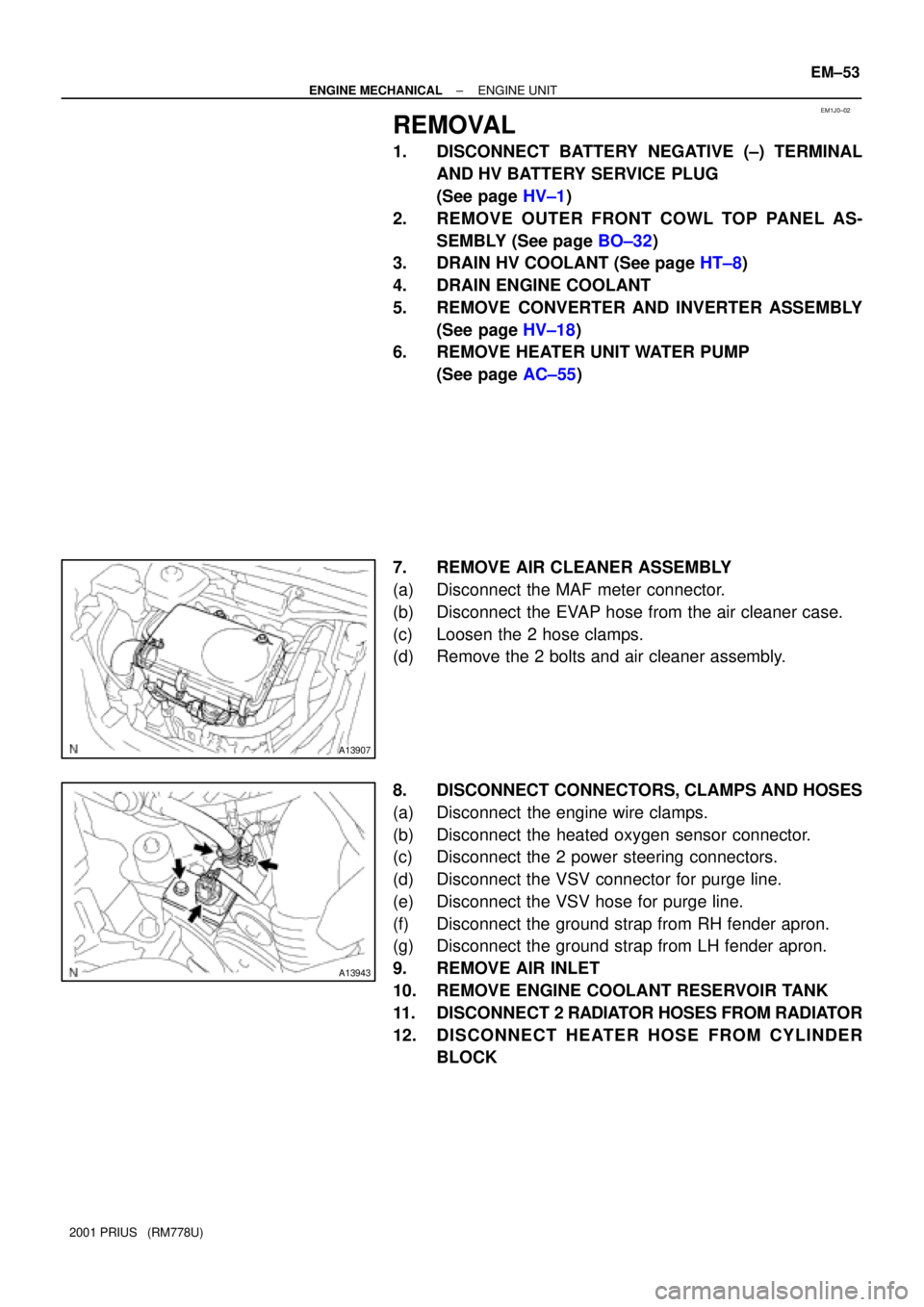
7. REMOVE AIR CLEANER ASSEMBLY
(a) Disconnect the MAF meter connector.
(b) Disconnect the EVAP hose from the air cleaner case.
(c) Loosen the 2 hose clamps.
(d) Remove the 2 bolts and air cleaner assembly.
8. DISCONNECT CONNECTORS, CLAMPS AND HOSES
(a) Disconnect the engine wire clamps.
(b) Disconnect the heated oxygen sensor connector.
(c) Disconnect the 2 power steering connectors.
(d) Disconnect the VSV connector for purge line.
(e) Disconnect the VSV hose for purge line.
(f) Disconnect the ground strap from RH fender apron.
(g) Disconnect the ground strap from LH fender apron.
9. REMOVE AIR INLET
10. REMOVE ENGINE COOLANT RESERVOIR TANK
11. DISCONNECT 2 RADIATOR HOSES FROM RADIATOR
12. DISCONNECT HEATER HOSE FROM CYLINDER
BLOCK
Page 1517 of 1943
A13939
I18009
A13909
A13938
EM±60
± ENGINE MECHANICALENGINE UNIT
2001 PRIUS (RM778U)
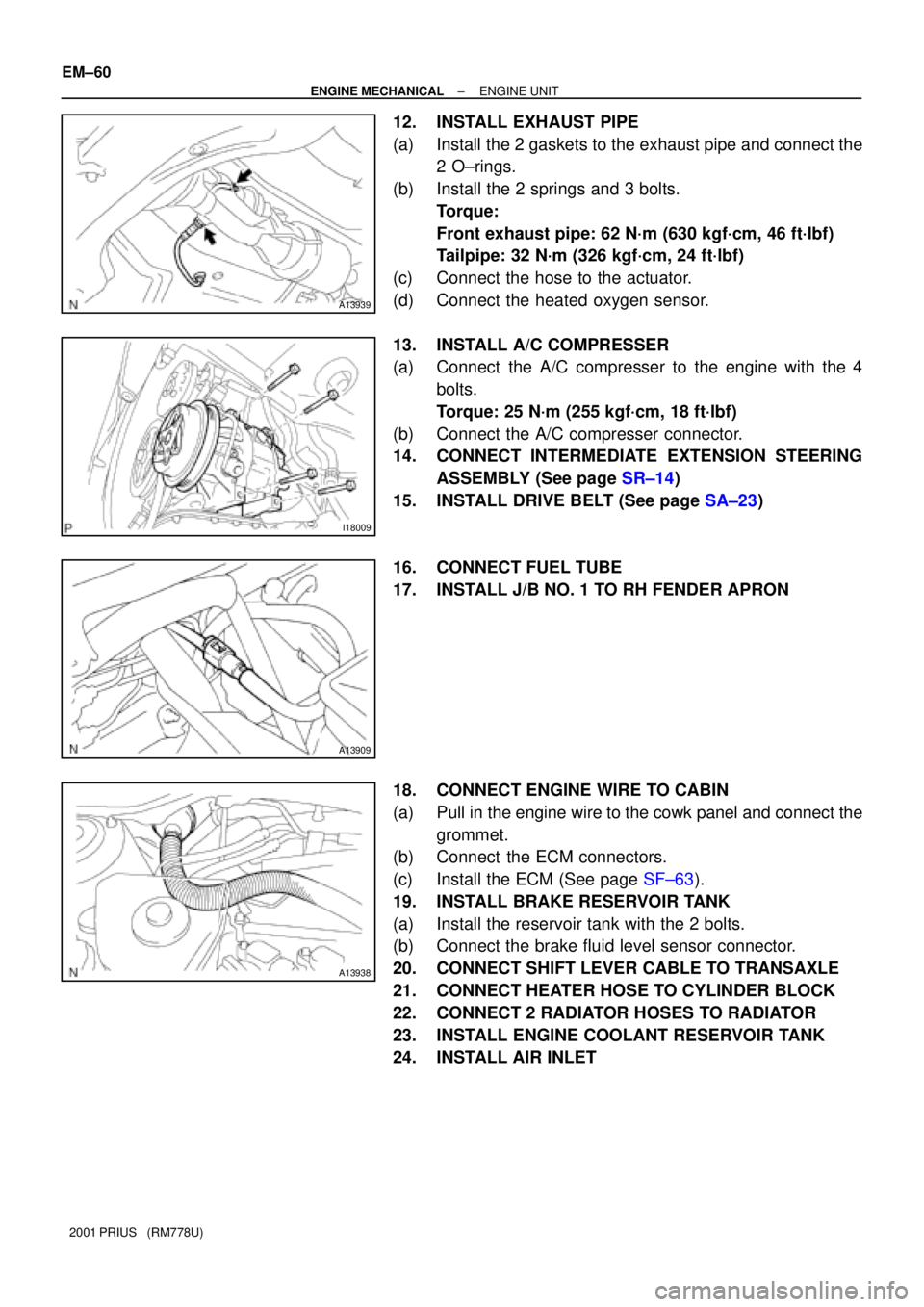
12. INSTALL EXHAUST PIPE
(a) Install the 2 gaskets to the exhaust pipe and connect the
2 O±rings.
(b) Install the 2 springs and 3 bolts.
Torque:
Front exhaust pipe: 62 N´m (630 kgf´cm, 46 ft´lbf)
Tailpipe: 32 N´m (326 kgf´cm, 24 ft´lbf)
(c) Connect the hose to the actuator.
(d) Connect the heated oxygen sensor.
13. INSTALL A/C COMPRESSER
(a) Connect the A/C compresser to the engine with the 4
bolts.
Torque: 25 N´m (255 kgf´cm, 18 ft´lbf)
(b) Connect the A/C compresser connector.
14. CONNECT INTERMEDIATE EXTENSION STEERING
ASSEMBLY (See page SR±14)
15. INSTALL DRIVE BELT (See page SA±23)
16. CONNECT FUEL TUBE
17. INSTALL J/B NO. 1 TO RH FENDER APRON
18. CONNECT ENGINE WIRE TO CABIN
(a) Pull in the engine wire to the cowk panel and connect the
grommet.
(b) Connect the ECM connectors.
(c) Install the ECM (See page SF±63).
19. INSTALL BRAKE RESERVOIR TANK
(a) Install the reservoir tank with the 2 bolts.
(b) Connect the brake fluid level sensor connector.
20. CONNECT SHIFT LEVER CABLE TO TRANSAXLE
21. CONNECT HEATER HOSE TO CYLINDER BLOCK
22. CONNECT 2 RADIATOR HOSES TO RADIATOR
23. INSTALL ENGINE COOLANT RESERVOIR TANK
24. INSTALL AIR INLET
Page 1521 of 1943
EM17C±04
A10451
A11268
A11269
A14342
EM±64
± ENGINE MECHANICALCYLINDER BLOCK
2001 PRIUS (RM778U)
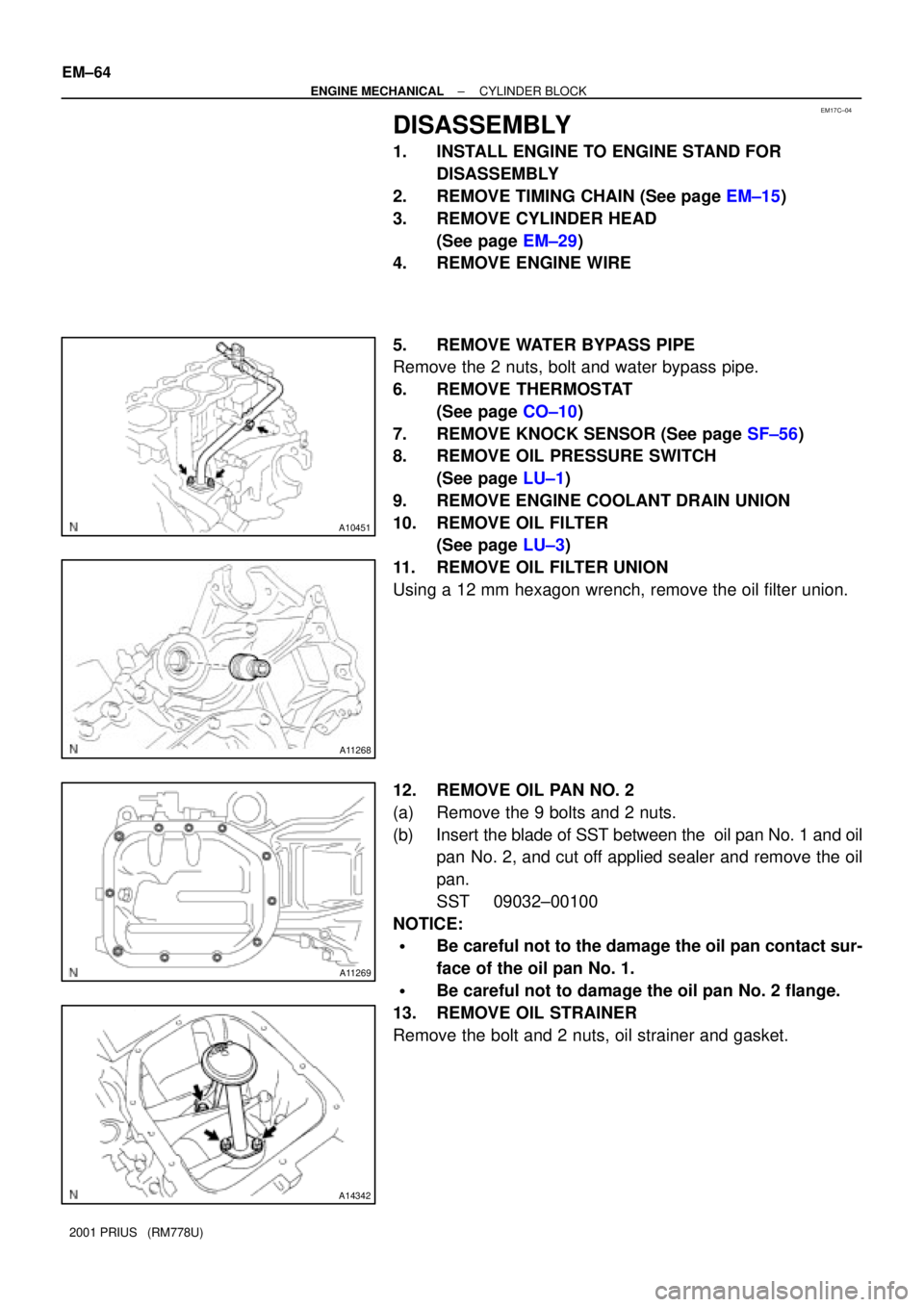
DISASSEMBLY
1. INSTALL ENGINE TO ENGINE STAND FOR
DISASSEMBLY
2. REMOVE TIMING CHAIN (See page EM±15)
3. REMOVE CYLINDER HEAD
(See page EM±29)
4. REMOVE ENGINE WIRE
5. REMOVE WATER BYPASS PIPE
Remove the 2 nuts, bolt and water bypass pipe.
6. REMOVE THERMOSTAT
(See page CO±10)
7. REMOVE KNOCK SENSOR (See page SF±56)
8. REMOVE OIL PRESSURE SWITCH
(See page LU±1)
9. REMOVE ENGINE COOLANT DRAIN UNION
10. REMOVE OIL FILTER
(See page LU±3)
11. REMOVE OIL FILTER UNION
Using a 12 mm hexagon wrench, remove the oil filter union.
12. REMOVE OIL PAN NO. 2
(a) Remove the 9 bolts and 2 nuts.
(b) Insert the blade of SST between the oil pan No. 1 and oil
pan No. 2, and cut off applied sealer and remove the oil
pan.
SST 09032±00100
NOTICE:
�Be careful not to the damage the oil pan contact sur-
face of the oil pan No. 1.
�Be careful not to damage the oil pan No. 2 flange.
13. REMOVE OIL STRAINER
Remove the bolt and 2 nuts, oil strainer and gasket.
Page 1522 of 1943
A11271
A11272
A10452
A10453
A10454
± ENGINE MECHANICALCYLINDER BLOCK
EM±65
2001 PRIUS (RM778U)
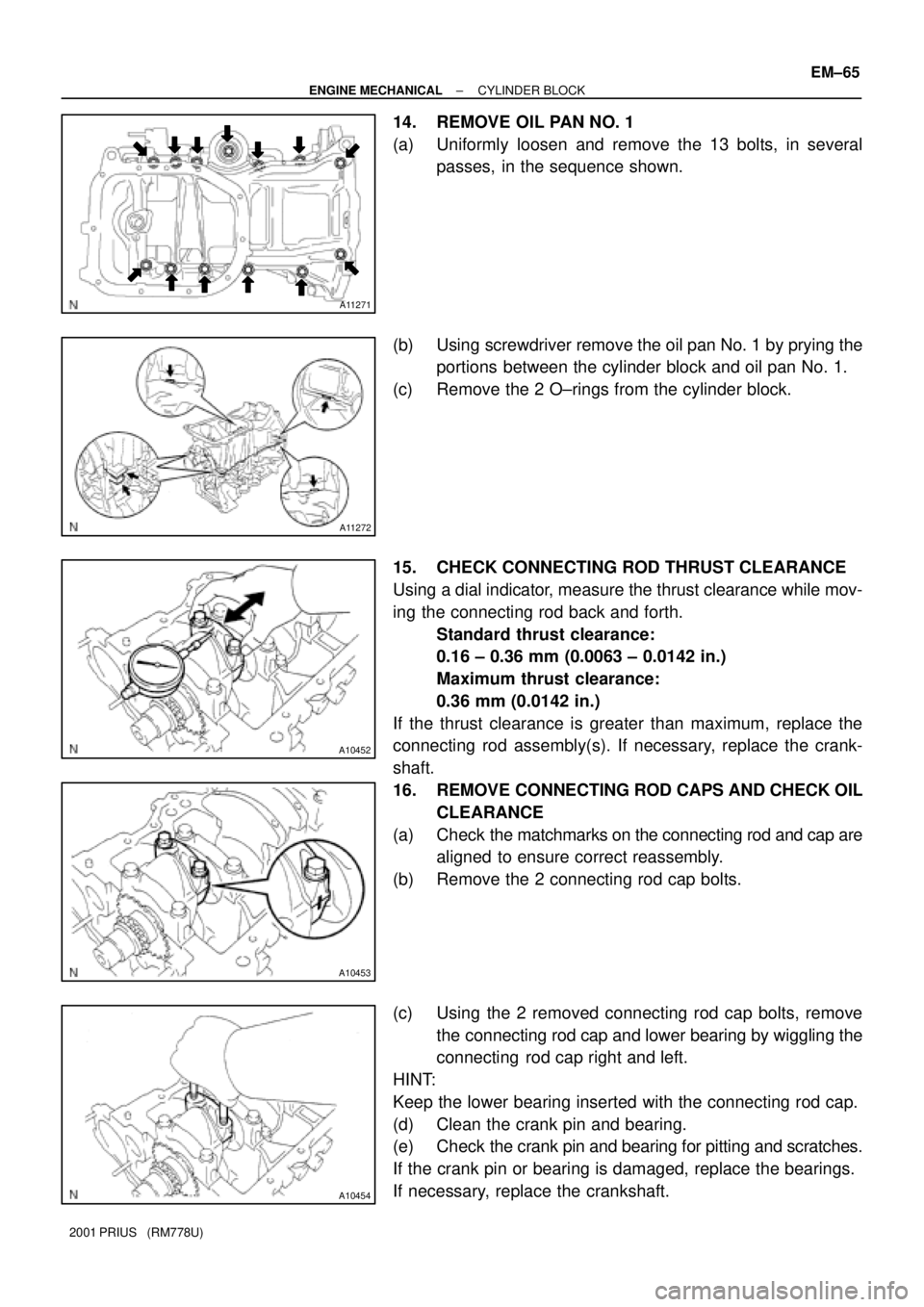
14. REMOVE OIL PAN NO. 1
(a) Uniformly loosen and remove the 13 bolts, in several
passes, in the sequence shown.
(b) Using screwdriver remove the oil pan No. 1 by prying the
portions between the cylinder block and oil pan No. 1.
(c) Remove the 2 O±rings from the cylinder block.
15. CHECK CONNECTING ROD THRUST CLEARANCE
Using a dial indicator, measure the thrust clearance while mov-
ing the connecting rod back and forth.
Standard thrust clearance:
0.16 ± 0.36 mm (0.0063 ± 0.0142 in.)
Maximum thrust clearance:
0.36 mm (0.0142 in.)
If the thrust clearance is greater than maximum, replace the
connecting rod assembly(s). If necessary, replace the crank-
shaft.
16. REMOVE CONNECTING ROD CAPS AND CHECK OIL
CLEARANCE
(a) Check the matchmarks on the connecting rod and cap are
aligned to ensure correct reassembly.
(b) Remove the 2 connecting rod cap bolts.
(c) Using the 2 removed connecting rod cap bolts, remove
the connecting rod cap and lower bearing by wiggling the
connecting rod cap right and left.
HINT:
Keep the lower bearing inserted with the connecting rod cap.
(d) Clean the crank pin and bearing.
(e) Check the crank pin and bearing for pitting and scratches.
If the crank pin or bearing is damaged, replace the bearings.
If necessary, replace the crankshaft.
Page 1523 of 1943
A10455
Plastigage
A10456
A10457
A01198
Mark
1, 2 or 3
Mark
1, 2 or 3
EM±66
± ENGINE MECHANICALCYLINDER BLOCK
2001 PRIUS (RM778U)
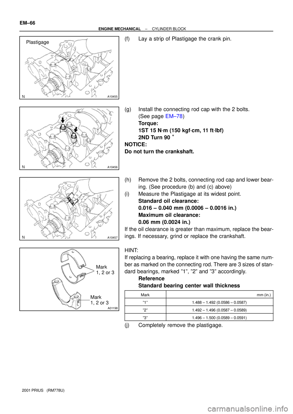
(f) Lay a strip of Plastigage the crank pin.
(g) Install the connecting rod cap with the 2 bolts.
(See page EM±78)
Torque:
1ST 15 N´m (150 kgf´cm, 11 ft´lbf)
2ND Turn 90 °
NOTICE:
Do not turn the crankshaft.
(h) Remove the 2 bolts, connecting rod cap and lower bear-
ing. (See procedure (b) and (c) above)
(i) Measure the Plastigage at its widest point.
Standard oil clearance:
0.016 ± 0.040 mm (0.0006 ± 0.0016 in.)
Maximum oil clearance:
0.06 mm (0.0024 in.)
If the oil clearance is greater than maximum, replace the bear-
ings. If necessary, grind or replace the crankshaft.
HINT:
If replacing a bearing, replace it with one having the same num-
ber as marked on the connecting rod. There are 3 sizes of stan-
dard bearings, marked º1º, º2º and º3º accordingly.
Reference
Standard bearing center wall thickness
Markmm (in.)
º1º1.488 ± 1.492 (0.0586 ± 0.0587)
º2º1.492 ± 1.496 (0.0587 ± 0.0589)
º3º1.496 ± 1.500 (0.0589 ± 0.0591)
(j) Completely remove the plastigage.