Page 306 of 1943
ENGINE ± 1NZ-FXE ENGINE
182EG22
Circuit
Opening
Relay
VSV
(for
EVAP)
Intake
Air Temp.
SensorThrottle
Position
Sensor
ECMHV
ECU
Accelera-
tor Pedal
Position
Sensor
Cooling
Fan Relay
Throttle
Control
Motor
Igniter
Camshaft Position Sensor
Knock
Sensor
Mass Air
Flow Meter
VSV
(for Toyota
HCAC
System)Vacuum
Sensor
(for Toyota
HCAC
System)
Crankshaft
Position Sensor Injector
Camshaft
Timing
Oil Con-
trol Valve
Engine
Coolant
Te m p .
Sensor
TWC
Heated Oxygen
Sensor (Bank 1,
Sensor 1)
Heated Oxygen
Sensor (Bank 1,
Sensor 2)
Actuator (for HC
Adsorber)
TWC (with HC
Adsorber)
VSV (for Purge Flow
Switching Valve)
Vapor Pressure Sensor
VSV (for Canister Closed Valve)
Charcoal
Canister
Fuel Pump65
3. Engine Control System Diagram
Page 307 of 1943
ENGINE ± 1NZ-FXE ENGINE
182EG23
VSV (for TOYOTA
HCAC System)VSV (for EVAP)Oil Control Valve
ECMIgnition Coil
with IgniterVSV (for Purge Flow Switching Valve)
Charcoal Canister
Vapor
Pressure
Sensor
Trap Filter
VSV (for Canister
Closed Valve) DLC 3
Heated Oxygen Sensor
(Bank 1, Sensor 2)
Heated Oxygen Sensor
(Bank 1, Sensor 1) Engien Coolant
Temp. Sensor Camshaft
Position
Sensor
Injector Crankshaft
Position
Sensor Knock
Sensor Throttle
Control
Motor Mass Air
Flow Meter 66
4. Layout of Components
Page 310 of 1943
ENGINE ± 1NZ-FXE ENGINE
185EG18
VVT-i Controller Housing
Vane
Rotating DirectionECM
Oil Pressure
185EG19
Rotating Direction
Oil PressureECM69
Operation
The camshaft timing oil control valve selects the path to the VVT-i controller according to the advance, re-
tard or hold signal from the ECM. The VVT-i controller rotates the intake camshaft in the timing advance
or retard position or holds it according to the position where the oil pressure is applied.
1) Advance
When the camshaft timing oil control valve is positioned as illustrated below by the advance signal from
the ECM, the resultant oil pressure is applied to the timing advance side vane chamber to rotate the cam-
shaft in the timing advance direction.
2) Retard
When the camshaft timing oil control valve is positioned as illustrated below by the retard signal from
the ECM, the resultant oil pressure is applied to the timing retard side vane chamber to rotate the camshaft
in the timing retard direction.
Page 507 of 1943

MA02E±02
± MAINTENANCEOUTSIDE VEHICLE
MA±1
54 Author�: Date�:
2001 PRIUS (RM778U)
OUTSIDE VEHICLE
GENERAL MAINTENANCE
These are maintenance and inspection items which are considered to be the owner's responsibility.
They can be done by the owner or they can have them done at a service shop.
These items include those which should be checked on a daily basis, those which, in most cases, do not
require (special) tools and those which are considered to be reasonable for the owner to do.
Items and procedures for general maintenance are as follows.
1. GENERAL NOTES
�Maintenance items may vary from country to country. Check the owner's manual supplement in which
the maintenance schedule is shown.
�Every service item in the periodic maintenance schedule must be performed.
�Periodic maintenance service must be performed according to whichever interval in the periodic main-
tenance schedule occurs first, the odometer reading (miles) or the time interval (months).
�Maintenance service after the last period should be performed at the same interval as before unless
otherwise noted.
�Failure to do even one item an cause the engine to run poorly and increase exhaust emissions.
2. TIRES
(a) Check the pressure with a gauge. If necessary, adjust.
(b) Check for cuts, damage or excessive wear.
3. WHEEL NUTS
When checking the tires, check the nuts for looseness or for missing nuts. If necessary, tighten them.
4. TIRE ROTATION
Check the owner's manual supplement in which the maintenance schedule is shown.
5. WINDSHIELD WIPER BLADES
Check for wear or cracks whenever they do not wipe clean. If necessary, replace.
6. FLUID LEAKS
Check underneath for leaking fuel, oil, water or other fluid.
7. DOORS AND ENGINE HOOD
(a) Check that all doors including the trunk lid operate smoothly, and that all latches lock securely.
(b) Check that the engine hood secondary latch secures the hood from opening when the primary latch
is released.
Page 587 of 1943

SS102±07
SS±12
± SERVICE SPECIFICATIONSSFI
134 Author�: Date�:
2001 PRIUS (RM778U)
SFI
SERVICE DATA
Fuel pumpResistance at 20°C (68°F)0.2 ± 3.0 W
InjectorResistance at 21 °C (68 °F)
Injection volume
Difference between each cylinder
Fuel leakage13.4 ± 14.2 W
36 ± 46 cm3 (2.1 ± 2.8 cu in.) per 15 sec.
10 cm3 (0.7 cu in.) or less
1 drop or less per 12 minutes
Mass air flow me-
ter
Resistance
at ±20°C (±4°F) THA ± E2
at 20°C (68°F) THA ± E2
at 60°C (140°F) THA ± E2
13.6 ± 18.4 kW
2.21 ± 2.69 kW
0.49 ± 0.67 kW
Throttle control
motorResistance
at 20°C (68°F) M+ ± M±
0.3 ± 100 W
Throttle position
sensorResistance
at 20°C (68°F) VC ± E2
1.2 ± 3.2 kW
VSV for EVAPResistance at 20°C (68°F)27 ± 33 W
VSV for CCVResistance at 20°C (68°F)25 ± 30 W
VSV for Purge
flow switching
valve
Resistance at 20°C (68°F)33 ± 39 W
VSV for HCACResistance at 20°C (68°F)33 ± 39 W
ECT sensorResistance at ±20°C (±4°F)
at 0°C (32°F)
at 20°C (68°F)
at 40°C (104°F)
at 60°C (140°F)
at 80°C (176°F)10 ± 20 kW
4 ± 7 kW
2 ± 3 kW
0.9 ± 1.3 kW
0.4 ± 0.7 kW
0.2 ± 0.4 kW
Vacuum sensor
for HCACPower sorce voltage4.5 ± 5.5 V
Vapor pressure
sevsorPower sorce voltage
Output voltage4.5 ± 5.5 V
3.0 ± 3.6 V
Heated
oxygen sensorHeater coil resistance at 20°C (68°F)11 ± 16 W
Accelerator pedal
position sensorResistance
at 20°C (68°F) Vcp
1 ± Ep1
Vcp2 ± Ep21.5 ± 6.0 kW
Fuel cut rpmFuel return rpm1,400 rpm
Page 618 of 1943
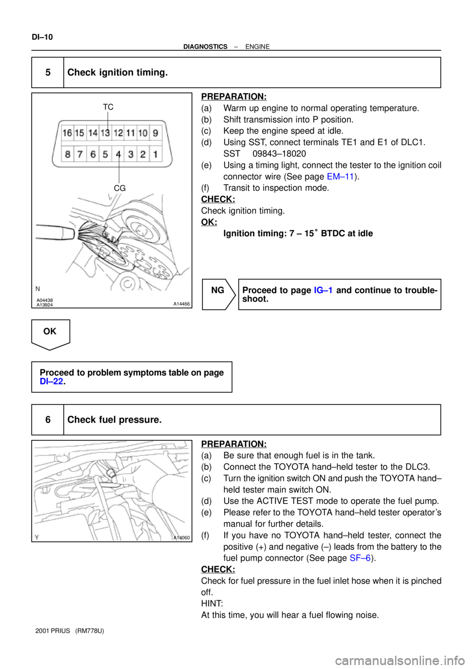
A04438A13924A14466
TC
CG
A14060
DI±10
± DIAGNOSTICSENGINE
2001 PRIUS (RM778U)
5 Check ignition timing.
PREPARATION:
(a) Warm up engine to normal operating temperature.
(b) Shift transmission into P position.
(c) Keep the engine speed at idle.
(d) Using SST, connect terminals TE1 and E1 of DLC1.
SST 09843±18020
(e) Using a timing light, connect the tester to the ignition coil
connector wire (See page EM±11).
(f) Transit to inspection mode.
CHECK:
Check ignition timing.
OK:
Ignition timing: 7 ± 15° BTDC at idle
NG Proceed to page IG±1 and continue to trouble-
shoot.
OK
Proceed to problem symptoms table on page
DI±22.
6 Check fuel pressure.
PREPARATION:
(a) Be sure that enough fuel is in the tank.
(b) Connect the TOYOTA hand±held tester to the DLC3.
(c) Turn the ignition switch ON and push the TOYOTA hand±
held tester main switch ON.
(d) Use the ACTIVE TEST mode to operate the fuel pump.
(e) Please refer to the TOYOTA hand±held tester operator's
manual for further details.
(f) If you have no TOYOTA hand±held tester, connect the
positive (+) and negative (±) leads from the battery to the
fuel pump connector (See page SF±6).
CHECK:
Check for fuel pressure in the fuel inlet hose when it is pinched
off.
HINT:
At this time, you will hear a fuel flowing noise.
Page 791 of 1943

DI±194
± DIAGNOSTICSHYBRID VEHICLE CONTROL SYSTEM
2001 PRIUS (RM778U)
0: When engine is stopped
1: When stopping engine
2: When starting engine
DRIVE CONDITION3: When cranking engine or engine is operatingDRIVE CONDITION
4: While generating power or load driving
5: ±
6: While racing engine in P position
DRIVING PATTEN1History of driving pattern 1
DRIVING PATTEN2History of driving pattern 2
DRIVING PATTEN3History of driving pattern 3
DRIVING PATTERNHIstory of driving
ECU TYPEECU type
ENG INDPDET RQFactors causing engine to run independently
ENG STOP RQSTEngine stop request
ENG STP INHIBITEngine stop inhibition
ENG WARM UP RQTEngine warming up request
ENGINE FUEL CUTEngine fuel cut
ENGINE SPDEngine speed
EXCLUSIVE INFO1Exclusive information 1
EXCLUSIVE INFO2Exclusive information 2
EXCLUSIVE INFO3Exclusive information 3
EXCLUSIVE INFO4Exclusive information 4
EXCLUSIVE INFO5Exclusive information 5
EXCLUSIVE INFO6Exclusive information 6
FUEL SHORTAGELow fuel
HCAC ABSRT RQSTHCAC OBD request
HV BATT CH RQSTRequest from HV ECU to charge the battery
HV ECU INTERMITTENTHV ECU intermittent problems
IDLING REQUESTEngine idling request
IG OFF IN DRVINTurning IG OFF while driving the car
IG OFF TIMEIG OFF time
ILK OPERATIONInterlock operation
INFORMATION 1±5Information code
INPUT V LOWInput voltage is too low
INPUT V OVERInput voltage is too high
INTAKE AIRIntake air temperature
INVERT TEMP±MG1Temperature of inverter MG1
INVERT TEMP±MG2Temperature of inverter MG2
LATEST OPERLatest number of operation
LATEST TRIPLatest number of trips (IG ON±OFF)
LOAD CONDITIONIndicating which of MG1 or MG2 the vehicle uses more
MAIN BATT LOWSOC of main battery becomes low
MCYL CTRL POWERTorque for controlling oil pressure of master cylinder
MG1 TEMP HIGHTemperature MG1 is too high
MG2 TEMP HIGHTemperature MG2 is too high
MG1 CURRENT VElectric current of MG1 V phase
Page 998 of 1943

± DIAGNOSTICSANTI±LOCK BRAKE SYSTEM WITH EBD & RBS
DI±421
2001 PRIUS (RM778U)
DTC C1253/53 Hydro Motor Relay Circuit
CIRCUIT DESCRIPTION
The hydro motor relay supplies power to the hydraulic brake booster pump motor. While the ABS & EBD &
RBS are activated, the ECU switches the motor relay ON and operates the hydraulic brake booster pump
motor.
DTC No.DTC Detecting ConditionTrouble Area
C1253/53
When any of the following 1. through 4. is detected:
1. After turning the ignition switch ON, open in the relay
coil is detected for more than 1 sec.
2. When the pressure switch does not control motor
driving, the status that the motor relay is always ON
continues for more than 1 sec. due to short circuit.
3. When the pressure switch (PH) detects the low
pressure or while the pump motor operates to increase
the pressure, the status that the motor relay does not
turn ON continues for more than 0.2 sec.
4. When pressure switch does not control motor driving,
the status that the motor relay is always ON due to the
welded contact continues for more than 2 sec.
�Hydro motor relay
�Hydro motor relay circuit
DI29A±13