Page 603 of 1943
SS0LM±06
SS±28
± SERVICE SPECIFICATIONSBRAKE
150 Author�: Date�:
2001 PRIUS (RM778U)
BRAKE
SERVICE DATA
BRAKE PEDAL
Brake pedal height from asphalt sheet127 ± 137 mm (5.08 ± 5.48 in.)
Brake pedal freeplay1 ± 6 mm (0.04 ± 0.24 in.)
Brake pedal reserve distance at 200 N (20 kgf, 45 Ibf)More than 85 mm (3.35 in.)
PARKING BRAKE PEDAL
Parking brake pedal travel at 294N (30 Kgf, 66.1 Ibf)5 ± 8 clicks
FRONT BRAKE
Front brake pad thickness STD11.0 mm (0.433 in.)
Front brake pad thickness Minimum1.0 mm (0.039 in.)
Front brake disc thickness STD22.0 mm (0.984 in.)
Front brake disc thickness Minimum20.0 mm (0.906 in.)
Front brake disc runout Maximum0.05 mm (0.0020 in.)
REAR BRAKE
Drum brake shoe lining thickness STD4.0 mm (0.157 in.)
Drum brake shoe lining thickness Minimum1.0 mm (0.039 in.)
Rear brake drum inside diameter STD200.0 mm (7.874 in.)
Rear brake drum inside diameterMaximum201.0 mm (7.913 in.)
Rear brake drum to shoe clearance0.6 mm (0.024 in.)
Page 1496 of 1943

EM2011
EM2538
A01452
Plastigage
A12943
A01453
EM±38
± ENGINE MECHANICALCYLINDER HEAD
2001 PRIUS (RM778U)
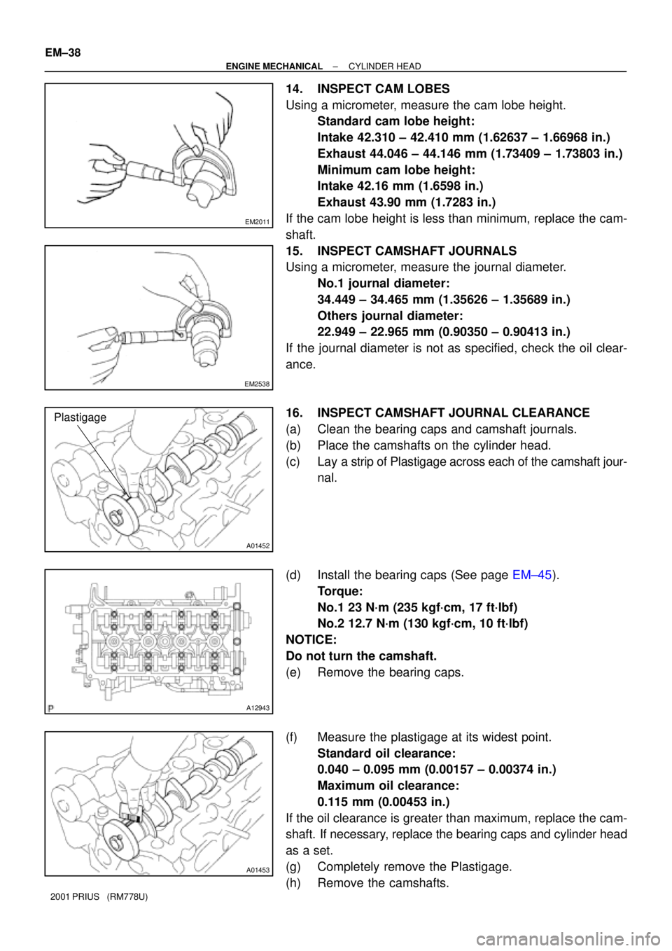
14. INSPECT CAM LOBES
Using a micrometer, measure the cam lobe height.
Standard cam lobe height:
Intake 42.310 ± 42.410 mm (1.62637 ± 1.66968 in.)
Exhaust 44.046 ± 44.146 mm (1.73409 ± 1.73803 in.)
Minimum cam lobe height:
Intake 42.16 mm (1.6598 in.)
Exhaust 43.90 mm (1.7283 in.)
If the cam lobe height is less than minimum, replace the cam-
shaft.
15. INSPECT CAMSHAFT JOURNALS
Using a micrometer, measure the journal diameter.
No.1 journal diameter:
34.449 ± 34.465 mm (1.35626 ± 1.35689 in.)
Others journal diameter:
22.949 ± 22.965 mm (0.90350 ± 0.90413 in.)
If the journal diameter is not as specified, check the oil clear-
ance.
16. INSPECT CAMSHAFT JOURNAL CLEARANCE
(a) Clean the bearing caps and camshaft journals.
(b) Place the camshafts on the cylinder head.
(c) Lay a strip of Plastigage across each of the camshaft jour-
nal.
(d) Install the bearing caps (See page EM±45).
Torque:
No.1 23 N´m (235 kgf´cm, 17 ft´lbf)
No.2 12.7 N´m (130 kgf´cm, 10 ft´lbf)
NOTICE:
Do not turn the camshaft.
(e) Remove the bearing caps.
(f) Measure the plastigage at its widest point.
Standard oil clearance:
0.040 ± 0.095 mm (0.00157 ± 0.00374 in.)
Maximum oil clearance:
0.115 mm (0.00453 in.)
If the oil clearance is greater than maximum, replace the cam-
shaft. If necessary, replace the bearing caps and cylinder head
as a set.
(g) Completely remove the Plastigage.
(h) Remove the camshafts.
Page 1499 of 1943

A01067
80 ± 100°C
EM16L±02
A01066
SST
A13949
Both intake and exhaust
Bushing bore diameter
mm (in.)Bushing size
9.685 ± 9.706
(0.38130 ± 0.38213)Use STD
9.735 ± 9.756
(0.38327 ± 0.38493)Use O/S 0.05
A01446
SST
± ENGINE MECHANICALCYLINDER HEAD
EM±41
2001 PRIUS (RM778U)
REPLACEMENT
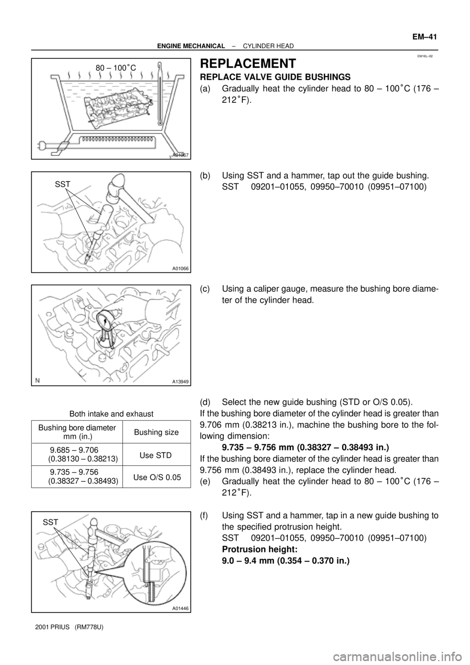
REPLACE VALVE GUIDE BUSHINGS
(a) Gradually heat the cylinder head to 80 ± 100°C (176 ±
212°F).
(b) Using SST and a hammer, tap out the guide bushing.
SST 09201±01055, 09950±70010 (09951±07100)
(c) Using a caliper gauge, measure the bushing bore diame-
ter of the cylinder head.
(d) Select the new guide bushing (STD or O/S 0.05).
If the bushing bore diameter of the cylinder head is greater than
9.706 mm (0.38213 in.), machine the bushing bore to the fol-
lowing dimension:
9.735 ± 9.756 mm (0.38327 ± 0.38493 in.)
If the bushing bore diameter of the cylinder head is greater than
9.756 mm (0.38493 in.), replace the cylinder head.
(e) Gradually heat the cylinder head to 80 ± 100°C (176 ±
212°F).
(f) Using SST and a hammer, tap in a new guide bushing to
the specified protrusion height.
SST 09201±01055, 09950±70010 (09951±07100)
Protrusion height:
9.0 ± 9.4 mm (0.354 ± 0.370 in.)
Page 1656 of 1943

F11573
Front:
Rear:SA1CK±11
Z03382
Alignment
TesterGauge
F07339
SA±4
± SUSPENSION AND AXLEFRONT WHEEL ALIGNMENT
1454 Author�: Date�:
2001 PRIUS (RM778U)
FRONT WHEEL ALIGNMENT
INSPECTION
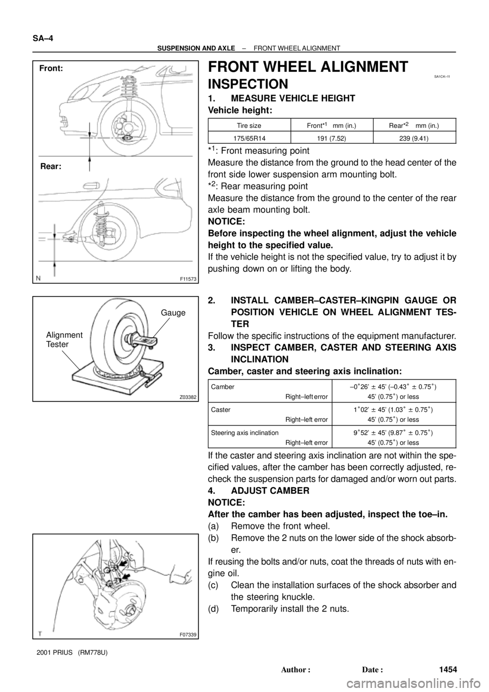
1. MEASURE VEHICLE HEIGHT
Vehicle height:
Tire sizeFront*1 mm (in.)Rear*2 mm (in.)
175/65R14191 (7.52)239 (9.41)
*1: Front measuring point
Measure the distance from the ground to the head center of the
front side lower suspension arm mounting bolt.
*
2: Rear measuring point
Measure the distance from the ground to the center of the rear
axle beam mounting bolt.
NOTICE:
Before inspecting the wheel alignment, adjust the vehicle
height to the specified value.
If the vehicle height is not the specified value, try to adjust it by
pushing down on or lifting the body.
2. INSTALL CAMBER±CASTER±KINGPIN GAUGE OR
POSITION VEHICLE ON WHEEL ALIGNMENT TES-
TER
Follow the specific instructions of the equipment manufacturer.
3. INSPECT CAMBER, CASTER AND STEERING AXIS
INCLINATION
Camber, caster and steering axis inclination:
Camber
Right±left error±0°26' ± 45' (±0.43° ± 0.75°)
45' (0.75°) or less
Caster
Right±left error1°02' ± 45' (1.03° ± 0.75°)
45' (0.75°) or less
Steering axis inclination
Right±left error9°52' ± 45' (9.87° ± 0.75°)
45' (0.75°) or less
If the caster and steering axis inclination are not within the spe-
cified values, after the camber has been correctly adjusted, re-
check the suspension parts for damaged and/or worn out parts.
4. ADJUST CAMBER
NOTICE:
After the camber has been adjusted, inspect the toe±in.
(a) Remove the front wheel.
(b) Remove the 2 nuts on the lower side of the shock absorb-
er.
If reusing the bolts and/or nuts, coat the threads of nuts with en-
gine oil.
(c) Clean the installation surfaces of the shock absorber and
the steering knuckle.
(d) Temporarily install the 2 nuts.