Page 1376 of 1943
± DIAGNOSTICSNAVIGATION SYSTEM
DI±867
2001 PRIUS (RM778U)
INSPECTION PROCEDURE
1 Check wire harness and connector between radio receiver assembly and naviga-
tion ECU (See page IN±41).
NG Repair or replace wire harness or connector be-
tween radio receiver assembly and navigation
ECU.
OK
2 Check wire harness and connector between multi display and navigation ECU
(See page IN±41).
NG Repair or replace wire harness or connector be-
tween multi display and navigation ECU.
OK
Page 1377 of 1943
I12172
Navigation ECUMulti DisplayRadio Receiver
Assembly
SST
TX± TX+TX± TX+
Radio receiver assembly connector ºR4º
DI±868
± DIAGNOSTICSNAVIGATION SYSTEM
2001 PRIUS (RM778U)
3 Skip radio receiver assembly and check AVC±LAN.
PREPARATION:
(a) Connect Multi Display connector.
(b) Disconnect radio receiver assembly ºR4º connector.
(c) Using SST (Navigation Check Wire P/N 09843±18050),
connect the terminal TX+ to terminal TX± of ºR4º connec-
tor of radio receiver assembly.
CHECK:
Operate the panel switch and the touch switch of the display
and check that the navigation functions.
(Check that AVC±LAN is recovered.)
OK Replace the radio receiver assembly.
NG
Replace the Navigation ECU.
Page 1382 of 1943

± DIAGNOSTICSAIR CONDITIONING SYSTEM
DI±875
2001 PRIUS (RM778U)42
(DI±909)
Air inlet control servomotor circuit
�Air inlet control servomotor
�Air inlet damper position sensor
�Harness or connector between air inlet control servomotor
and A/C amplifier
�A/C amplifier
43
(DI±912)Air outlet control servomotor circuit
�Air outlet control servomotor
�Air outlet damper position sensor
�Harness or connector between air outlet control servomotor
and A/C amplifier
�A/C amplifier
HINT:
�*1: If the room temp. is approx. ±18.6°C (±3.7°F) or lower, trouble code 11 may be output even though
the system is normal.
�*2: If the ambient temp. is approx. ±52.9°C (±61.4°F) or lower, a malfunction code may be output even
though the system is normal.
�*3: If the check is being performed in a dark place, DTC 21 (solar sensor circuit abnormal) could be
displayed.
�*4: To confirm DTC 22, perform the following steps.
(1) With the engine is running, enter the DTC check mode.
(2) Enter actuator check mode and set the operation to step NO. 1.
(3) Check that the DTC 22 is output.
Page 1392 of 1943
I18175
ON
E2
TA M
(±) (+)
ECM terminals
± DIAGNOSTICSAIR CONDITIONING SYSTEM
DI±885
2001 PRIUS (RM778U)
INSPECTION PROCEDURE
1 Check voltage between terminals TAM and E2 of ECM connector.
PREPARATION:
(a) Remove ECM with connectors still connected.
(b) Turn ignition switch ON.
CHECK:
Check voltage between terminals TAM and E2 of ECM connec-
tor at each temperature .
OK:
Voltage
at 25 °C (77 °F) : 1.35 ± 1.75 V
at 40 °C (104 °F) : 0.85 ± 1.25 V
HINT:
As the temperature increases, the voltage decreases.
NG Go to step 2.
OK
Proceed to the next circuit inspection shown on problem symptoms table (See page DI±874).
However, if DTC 12 is displayed, check and replace A/C amplifier.
Page 1395 of 1943

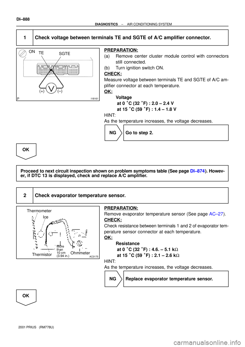
I18161
ON
SGTE TE
(±) (+)
AC0175
Thermometer
Ice
ThermistorOhmmeter
More
than
10 cm
(3.94 in.)
DI±888
± DIAGNOSTICSAIR CONDITIONING SYSTEM
2001 PRIUS (RM778U)
1 Check voltage between terminals TE and SGTE of A/C amplifier connector.
PREPARATION:
(a) Remove center cluster module control with connectors
still connected.
(b) Turn ignition switch ON.
CHECK:
Measure voltage between terminals TE and SGTE of A/C am-
plifier connector at each temperature.
OK:
Voltage
at 0 °C (32 °F) : 2.0 ± 2.4 V
at 15 °C (59 °F) : 1.4 ± 1.8 V
HINT:
As the temperature increases, the voltage decreases.
NG Go to step 2.
OK
Proceed to next circuit inspection shown on problem symptoms table (See page DI±874). Howev-
er, if DTC 13 is displayed, check and replace A/C amplifier.
2 Check evaporator temperature sensor.
PREPARATION:
Remove evaporator temperature sensor (See page AC±27).
CHECK:
Check resistance between terminals 1 and 2 of evaporator tem-
perature sensor connector at each temperature.
OK:
Resistance
at 0 °C (32 °F) : 4.6. ± 5.1 kW
at 15 °C (59 °F) : 2.1 ± 2.6 kW
HINT:
As the temperature increases, the voltage decreases.
NG Replace evaporator temperature sensor.
OK
Page 1400 of 1943
Resistance of photodiode
Strength of solar radiationWeak Strong
High
Low
I18378
A/C Amplifier
A12
A/C Solar
Sensor
A9A9
TSS5TS
5 6
1
2W
W
± DIAGNOSTICSAIR CONDITIONING SYSTEM
DI±893
2001 PRIUS (RM778U)
DTC 21 Solar Sensor Circuit
CIRCUIT DESCRIPTION
A photo diode in the solar sensor detects solar radiation and
sends signals to the A/C amplifier.
DTC No.Detection ItemTrouble Area
Open or short in solar sensor circuit�Solar sensor
21
Open or short in solar sensor circuit.
(Please note that display of DTC 21 is not abnormal when the�Harness or connector between solar sensor and A/C amplifi-
er(y
sensor is not receiving solar radiation.)er.
�A/C amplifier.
WIRING DIAGRAM
DI7S9±01
Page 1401 of 1943
I18163
ON
(±)TS
S5TS
(+)
DI±894
± DIAGNOSTICSAIR CONDITIONING SYSTEM
2001 PRIUS (RM778U)
INSPECTION PROCEDURE
1 Check voltage between terminals S5TS and TS of A/C amplifier connector.
PREPARATION:
(a) Remove center cluster module control with connectors
still connected.
(b) Turn ignition switch ON.
CHECK:
Measure voltage between terminals S5TS and TS of A/C ampli-
fier connector when the solar sensor is subjected to an electric
light, and when the sensor is covered by a cloth.
OK:
ConditionVoltage
Sensor subjected to electric lightBelow 4.0 V
Sensor covered by a cloth4.0 ± 4.5 V
HINT:
As the inspection light is gradually moved away from the sen-
sor, the voltage increases.
NG Go to step 2.
NG
Proceed to next circuit inspection shown on problem symptoms table (See page DI±874). Howev-
er, if DTC 21 is displayed, check and replace A/C amplifier.
Page 1405 of 1943
DI±898
± DIAGNOSTICSAIR CONDITIONING SYSTEM
2001 PRIUS (RM778U)
3 Check harness and connector between A/C amplifier and compressor lock sen-
sor (See page IN±41).
NG Repair or replace harness or connector.
OK
Proceed to next circuit inspection shown on problem symptoms table (See page DI±874). Howev-
er, if DTC 22 is displayed, check and replace A/C amplifier.