Page 1410 of 1943
I18165
SGTP
TPON
(+)(±)
± DIAGNOSTICSAIR CONDITIONING SYSTEM
DI±903
2001 PRIUS (RM778U)
INSPECTION PROCEDURE
1 Check voltage between terminals TP and SGTP of A/C amplifier connector.
PREPARATION:
(a) Remove center cluster module control with connectors
still connected.
(b) Turn ignition switch ON.
CHECK:
Change the set temperature to activate the air mix damper, and
measure the voltage between terminals TP and SGTP of A/C
amplifier connector each time when the set temperature is
changed.
OK:
Set TemperatureVoltage
Max. COOL3.5 ± 4.5 V
Max. WARM0.5 ± 1.8 V
HINT:
As the set temperature increases, the voltage decreases grad-
ually without interruption.
NG Go to step 2.
OK
Proceed to next circuit inspection shown on problem symptoms table (See page DI±874).
However, if DTC 31 or 41 is displayed, check and replace A/C amplifier.
Page 1413 of 1943
I18164
SGTPI
TPION
(±) (+)
DI±906
± DIAGNOSTICSAIR CONDITIONING SYSTEM
2001 PRIUS (RM778U)
INSPECTION PROCEDURE
1 Check voltage between terminals TPI and SGTPI of A/C amplifier connector.
PREPARATION:
(a) Remove center cluster module control with connectors
still connected.
(b) Turn ignition switch ON.
CHECK:
Press REC/FRS switch to change air inlet between fresh and
recirculation air and measure voltage between terminals TPI
and SGTPI of A/C amplifier when the air inlet servomotor oper-
ates.
OK:
REC/FRS SwitchVoltage
REC3.5 ± 4.5 V
FRS0.5 ± 1.8 V
HINT:
As the air inlet control servomotor is moved from REC side to
FRS side, the voltage decreases gradually without interruption.
NG Go to step 2.
OK
Proceed to next circuit inspection shown on problem symptoms table (See page DI±874). Howev-
er, if DTC 32 or 42 is displayed, check and replace A/C amplifier.
Page 1416 of 1943
I18166
ON
(+) (±)SGTPM
TPM
± DIAGNOSTICSAIR CONDITIONING SYSTEM
DI±909
2001 PRIUS (RM778U)
1 Check voltage between terminals TPM and SGTPM of A/C amplifier connector.
PREPARATION:
(a) Remove center cluster module control with connectors
still connected.
(b) Turn ignition switch ON.
CHECK:
Measure the voltage between terminals TPM and SGTPM of
A/C amplifier.
OK:
Air inlet selectorVoltage
FACE3.5 ± 4.5 V
DEF0.5 ± 1.5 V
HINT:
As the air outlet damper control servomotor is moved from
FACE side to DEF side, the voltage decreases gradually with-
out interruption.
NG Go to step 2.
OK
Proceed to next circuit inspection shown on problem symptoms table (See page DI±874). Howev-
er, if DTC 34 or 44 is displayed, check and replace A/C amplifier.
Page 1782 of 1943
BE1VS±02
I18849
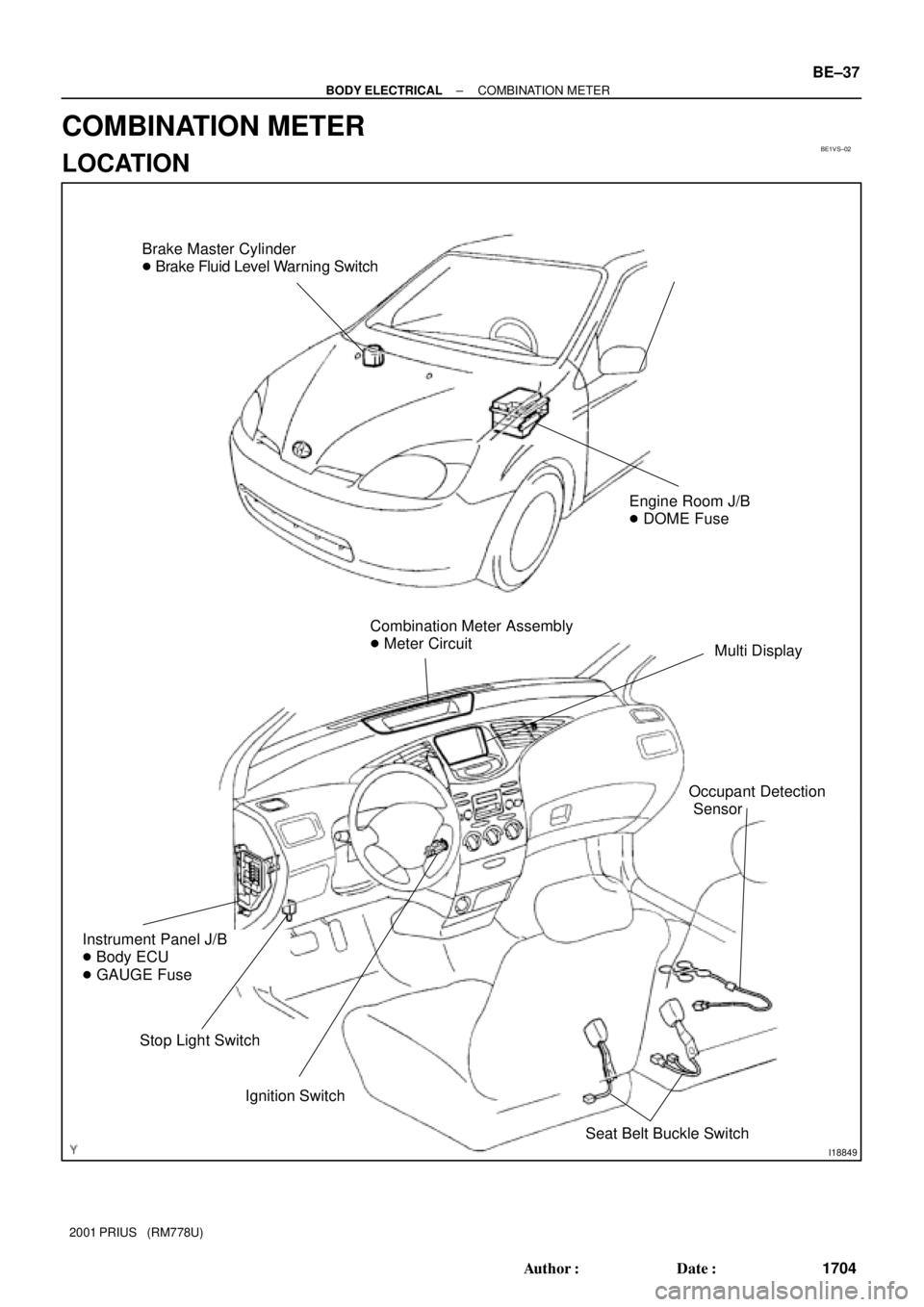
Brake Master Cylinder
� Brake Fluid Level Warning Switch
Combination Meter Assembly
� Meter Circuit
Multi Display
Ignition Switch
Instrument Panel J/B
� Body ECU
� GAUGE Fuse
Stop Light Switch
Engine Room J/B
� DOME Fuse
Seat Belt Buckle Switch
Occupant Detection
Sensor
± BODY ELECTRICALCOMBINATION METER
BE±37
1704 Author�: Date�:
2001 PRIUS (RM778U)
COMBINATION METER
LOCATION
Page 1833 of 1943
BE1UV±01
I17103
Audio system normal operation
to 2. SYSTEM CHECK MODE SCREEN
to 4. DISPLAY
CHECK MODE SCREEN Diagnosis start±up. (refer to next page)
HINT:
When Diagnosis Sys-
tem mode is started,
system check is per-
formed at first and the
check result is dis-
played.
± BODY ELECTRICALAUDIO SYSTEM
BE±97
2001 PRIUS (RM778U)
TROUBLESHOOTING
1. DIAGNOSIS SYSTEM MODE (w/o Navigation system)
HINT:
Diagnosis System Mode is operated as follows.
In case of a vehicle without navigation system, there is no navigation check mode. However, other modes
except for this are same as a vehicle with navigation system.
Page 1834 of 1943
I15593
I17110
Concealed
touch
switch
BE±98
± BODY ELECTRICALAUDIO SYSTEM
2001 PRIUS (RM778U)
(a) DIAGNOSIS START±UP
To start the diagnosis menu, there are 2 ways: using a
diagnosis check wire and using a switch.
(b) START±UP BY SWITCH OPERATION
(1) Vehicle speed is 0 km/h (0 mph).
(2) Parking brake switch is pressed.
(3) Press the Display switch to display the Screen Ad-
justment screen.
(4) Repeatedly touch the upper and lower bottom parts
of the left end of the screen 3 times.
(c) FINISHING DIAGNOSIS SYSTEM MODE
Turn the ignition switch from ACC to OFF to finish the
mode. If it is started by switch operation.
2. DIAGNOSIS SYSTEM MODE (w/ Navigation system)
(See page DI±789)
Page 1835 of 1943
 E
ILL
B
ACCPower Source
(System Operation)
Power Source
(Display Operation)
2
3
4Connector:
Clock Side:Wire Harness Side:
1 CLOCK WILL NOT OPERATE
I")
BE1UT±01
I01856
Ground
Power Source
(Illumination) E
ILL
B
ACCPower Source
(System Operation)
Power Source
(Display Operation)
2
3
4Connector:
Clock Side:Wire Harness Side:
1 CLOCK WILL NOT OPERATE
I01857
B + GND
e±4±2±D e±4±1±D
Clock Side:
Wire Harness Side:
Ye s
Ye sNo
No
Is there battery positive voltage between terminal +B and body
ground.
Is there continuity between terminal GND and body ground.
Replace clock.Open or short circuit in wire harness between terminal
+B and DOME fuse.
Open or short circuit in wire harness between terminal
GND and DOME fuse.
BE±102
± BODY ELECTRICALCLOCK
1769 Author�: Date�:
2001 PRIUS (RM778U)
CLOCK
TROUBLESHOOTING
HINT:
Troubleshoot the clock according to the table below.
TroubleshootingNo.
Clock will not operate1
Clock loses or gains time2
± 1.5 seconds / day
1. TROUBLESHOOTING No.1
(a) Check that the battery positive voltage is 10 ± 16 V.
If voltage is not as specified, replace the battery.
(b) Check that the DOME fuse is not blown.
If the fuse is blown, replace the fuse and check for short.
(c) Troubleshoot the clock as follows.
HINT:
Inspect the connector on the wire harness side.
Page 1843 of 1943

PRE±CH")
BE1WC±01
I17846
Check Connector
OP1
I01826
Example
ON
OFF
Code 11 Code 21
4.5 sec. 2.5 sec. 1.5 sec.
0.5
sec.
± BODY ELECTRICALHYBRID VEHICLE IMMOBILISER SYSTEM
BE±111
2001 PRIUS (RM778U)
PRE±CHECK
1. TRANSPONDER KEY ECU INPUT CONDITION DIS-
PLAY READ CODE
(a) Connect the positive (+) lead from the volt meter (Analog
Type) to OP1 of the check connector and the negative (±)
lead to E1 of the check connector.
(b) Insert the ignition key in the key cylinder.
(c) Read the code from the movement of the tester needle.
If no code is output, turn the ignition switch ON.
If a code is now output, check if the DOME fuse is blown.
HINT:
�The code can be read using a luminous diode (Recom-
mend activation current 10 ± 20 mA) instead of a tester.
�A digital tester can also be used.
Display condition:
�When there are multiple codes, they are output in order
staring from the lowest code.
�After all the codes are output, Lo is displayed for 4.5
secs., then all the code are output again starting from the
lowest code.
�If the situation changes during code output, Lo is output
for 4.5 secs. after output of the current code ceases, then
the codes are output again starting from the lowest code.
E.g. while 11 (out of 11 and 21) is being output, conditions
change and 12 is added. So after 11 is output, Lo is output
for 4.5 secs., then 11, 12 and 21 are output.
2. TRANSPONDER KEY ECU INPUT CONDITION DIS-
PLAY CODE LIST
CodeOutput condition
11Key unlock warning switch ON (Ignition key inserted)
12Any door is open. (Door courtesy switch ON)
13Ignition switch at ON position
21Master key is inserted in key cylinder and the immobiliser system
is OFF.
22Sub key is inserted in key cylinder and immobiliser system is
OFF.
31Key code recorded in transponder key ECU differs from code of
key inserted in key cylinder.
32Transponder key code cannot be read.
33Key code cannot be read because format of chip inside key is
wrong.
34Transponder key ECU has no memory space to register key
code.
52Hibrid vehicle control ECU is unlocked.
(±)
± DIAGNOSTICSAIR CONDITIONING SYSTEM
DI±903
2001 PRIUS (RM778U)
INSPECTION PROCEDURE
1 Check voltage between terminals TP and SGTP of A/C amplifier connector.
PREPARATION:")
 (+)
DI±906
± DIAGNOSTICSAIR CONDITIONING SYSTEM
2001 PRIUS (RM778U)
INSPECTION PROCEDURE
1 Check voltage between terminals TPI and SGTPI of A/C amplifier connector.
PREPARA")
 (±)SGTPM
TPM
± DIAGNOSTICSAIR CONDITIONING SYSTEM
DI±909
2001 PRIUS (RM778U)
1 Check voltage between terminals TPM and SGTPM of A/C amplifier connector.
PREPARATION:
(a) Remove cent")

HINT:
When Diagnosis Sys-
tem mode is started,")

(a) DIAGNOSIS START±UP
To start the diagnosis menu, there are 2 ways: using a
diagnosis check wire")