Page 2018 of 2572

H45941
Airbag Sensor
Assy Center
A175
E1 E2
27IG2
1
Battery28 7IGN Instrument Panel J/B
IG2
6 YAM2
GR
1LB
A17
A17 1C
IAW-B
W-B W-B14
9
1L 1L
1D L-Y 1
IC1
FL MAINW F7 FL Block
WI15
Ignition SW
Instrument Panel J/BAM2
10
1 16
- DIAGNOSTICSSUPPLEMENTAL RESTRAINT SYSTEM
05-1515
1705 Author�: Date�:
2005 HIGHLANDER REPAIR MANUAL (RM1144U)
SOURCE VOLTAGE DROP
CIRCUIT DESCRIPTION
The SRS is equipped with a voltage-increase circuit (DC-DC converter) in the airbag sensor assy center
in case the source voltage drops.
When the battery voltage drops, the voltage-increase circuit (DC-DC converter) functions to increase the
voltage of the SRS to normal voltage.
A malfunction in this circuit is displayed differently from other codes. The source voltage drop is indicated
when the SRS warning light comes on without showing any DTCs.
A malfunction in this circuit is not recorded in the airbag sensor assy center. The SRS warning light automati-
cally goes off when the source voltage returns to normal.
DTC No.Diagnosis
(Normal)Source voltage drop
WIRING DIAGRAM
05267-05
Page 2019 of 2572

INSPECTION PROCEDURE
1 CHECK SOURCE VOLTAGE
(a) Turn the ignition")
H40065
A17 IG2
E2
E1
05-1516
- DIAGNOSTICSSUPPLEMENTAL RESTRAINT SYSTEM
1706 Author�: Date�:
2005 HIGHLANDER REPAIR MANUAL (RM1144U)
INSPECTION PROCEDURE
1 CHECK SOURCE VOLTAGE
(a) Turn the ignition switch to the LOCK position.
(b) Disconnect the negative (-) terminal cable from the bat-
tery, and wait for at least 90 seconds.
(c) Disconnect the connector of the airbag sensor assy cen-
ter.
(d) Connect the negative (-) terminal cable to the battery,
and wait for at least 2 seconds.
(e) Turn the ignition switch to the ON position.
(f) Measure the voltage and resistance according to the val-
ue(s) in the table below.
Standard:
Tester connectionConditionSpecified condition
A17-5 (IG2) -
Body groundIgnition switch ON10 to 14 V
A17-27 (E1) -
Body groundAlwaysBelow 1 W
A17-28 (E2) -
Body groundAlwaysBelow 1 W
NG REPAIR OR REPLACE WIRE HARNESS
(BATTERY - AIRBAG SENSOR ASSY CENTER),
CHARGING SYSTEM AND BATTERY
OK
2 CHECK SRS WARNING LIGHT
(a) Turn the ignition switch to the LOCK position.
(b) Disconnect the negative (-) terminal cable from the battery, and wait for at least 90 seconds.
(c) Connect the airbag sensor assy center connectors.
(d) Connect the negative (-) terminal cable to the battery, and wait for at least 2 seconds.
(e) Turn the ignition switch to the ON position.
(f) Operate all components of the electrical system (defogger, wiper, headlight, heater blower, etc.) and
check the SRS warning light operation.
OK:
SRS warning light does not come on.
NG REPLACE AIR BAG SENSOR ASSY CENTER
(SEE PAGE 60-53)
OK
END
Page 2021 of 2572
H45942
Airbag Sensor
Assy Center
A1724
Y 1
Combination Meter4A5
11
FL MAINShort Connector
GR
I15
Ignition SWBR
IB2 IF310
12 9MPX1
MPX2
A1722
1 IB2
3CC11 2
A11
Body ECUIL2
B9 54F
B10 7
6
121
C11
C11C12
IB F7 FL Block P51 1
2 2S30
S30 S31S31 MPD1
MPD2 9
A10MPX+
MPX-
MPX1
MPX2
MPX1
MPX2
3A12
2
3B 3K
13
1K7
IC
ALT
1
1ABR R G V G
BR
SB
YOW
SB 4 11
7
8
P B
G
WW
BatteryAM1 HEATERG5
Gate Way ECU A/C
Control Assembly
E6
Engine
Control Module Passenger Side J/B
V
IL21
MPX2
MPX1
3J12
3E1 3H5
MPX1
6
1C Instrument Panel J/B
AM1 2
4
IG1 Instrument Panel J/B
B BY
Center J/B T4
Theft Deterrent ECU(*1) (*1)12
SW with ECU Power Window Master
GR
V31
(*3) Center J/B
GSB *1: w/ Navigation System
*2: w/o Navigation System
*3: w/ Theft Deterrent System G
(*2)
18
29
12
12RBR 05-1518
- DIAGNOSTICSSUPPLEMENTAL RESTRAINT SYSTEM
1708 Author�: Date�:
2005 HIGHLANDER REPAIR MANUAL (RM1144U)
WIRING DIAGRAM
Page 2022 of 2572

INSPECTI")
H40452
Airbag Sensor Assy Center:
Combination Meter Assy:MPX1
C11-21
A17
MPX2
- DIAGNOSTICSSUPPLEMENTAL RESTRAINT SYSTEM
05-1519
1709 Author�: Date�:
2005 HIGHLANDER REPAIR MANUAL (RM1144U)
INSPECTION PROCEDURE
1 CHECK CONNECTOR
(a) Turn the ignition switch to the LOCK position.
(b) Disconnect the negative (-) terminal cable from the battery, and wait for at least 90 seconds.
(c) Check that the connectors are properly connected to the airbag sensor assy center and the combina-
tion meter assy.
OK:
The connectors are connected.
NG CONNECT CONNECTORS
OK
2 CHECK WIRE HARNESS
(a) Turn the ignition switch to the LOCK position.
(b) Disconnect the negative (-) terminal cable from the bat-
tery, and wait for at least 90 seconds.
(c) Disconnect the connector from the airbag sensor assy
center.
(d) Measure the resistance according to the value(s) in the
table below.
Standard:
Tester connectionConditionSpecified condition
A17-24 (MPX1) - C11-21AlwaysBelow 1 W
A17-24 (MPX1) -
A17-22 (MPX2)Always1 MW or Higher
NG REPAIR OR REPLACE WIRE HARNESS
(AIRBAG SENSOR ASSY CENTER -
COMBINATION METER ASSY)
OK
Page 2023 of 2572
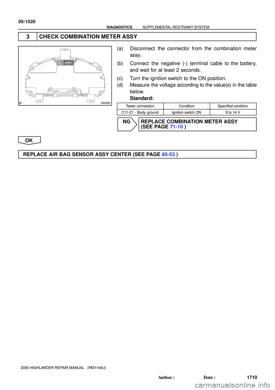
C82952
05-1520
- DIAGNOSTICSSUPPLEMENTAL RESTRAINT SYSTEM
1710 Author�: Date�:
2005 HIGHLANDER REPAIR MANUAL (RM1144U)
3 CHECK COMBINATION METER ASSY
(a) Disconnect the connector from the combination meter
assy.
(b) Connect the negative (-) terminal cable to the battery,
and wait for at least 2 seconds.
(c) Turn the ignition switch to the ON position.
(d) Measure the voltage according to the value(s) in the table
below.
Standard:
Tester connectionConditionSpecified condition
C11-21 - Body groundIgnition switch ON8 to 14 V
NG REPLACE COMBINATION METER ASSY
(SEE PAGE 71-10)
OK
REPLACE AIR BAG SENSOR ASSY CENTER (SEE PAGE 60-53)
Page 2024 of 2572

SRS WARNING LIGHT CIRCUIT MALFUNCTION (DOES NOT LIGHT
UP, WHEN IGNITION SWITCH IS TURN")
- DIAGNOSTICSSUPPLEMENTAL RESTRAINT SYSTEM
05-1521
1711 Author�: Date�:
2005 HIGHLANDER REPAIR MANUAL (RM1144U)
SRS WARNING LIGHT CIRCUIT MALFUNCTION (DOES NOT LIGHT
UP, WHEN IGNITION SWITCH IS TURNED TO ON)
CIRCUIT DESCRIPTION
The SRS warning light is located on the combination meter.
When the SRS is normal, the SRS warning light lights up for approx. 6 seconds after the ignition switch is
turned from the LOCK position to ON position, and then turns off automatically.
If there is a malfunction is the SRS, the SRS warning light lights up to inform the driver of the abnormality.
When terminals Tc and CG of the DLC3 are connected, the DTC is displayed by blinking the SRS warning
light.
WIRING DIAGRAM
see page 05-1517.
INSPECTION PROCEDURE
1 CHECK BATTERY
(a) Measure the voltage of the battery.
Standard: 11 to 14 V
NG REPLACE BATTERY
OK
2 CHECK WIRE HARNESS
(a) Turn the ignition switch to the LOCK position.
(b) Disconnect the negative (-) terminal cable from the battery, and wait for at least 90 seconds.
(c) Disconnect the connector from the airbag sensor assy center.
(d) Connect the negative (-) terminal cable from the battery, and wait for at least 2 seconds.
(e) Turn the ignition switch to the ON position.
(f) Measure the resistance according to the value(s) in the table below.
OK:
The SRS warning light comes on.
NG REPAIR OR REPLACE WIRE HARNESS
(COMBINATION METER - BATTERY)
OK
REPLACE COMBINATION METER ASSEMBLY (SEE PAGE 71-10)
05269-04
Page 2029 of 2572

5 INSPECT POWER WINDOW REGULATOR MOTOR A")
B51847
Driving Axis
ClockwiseCounterclock-
wise
- DIAGNOSTICSPOWER WINDOW CONTROL SYSTEM
05-1919
2109 Author�: Date�:
2005 HIGHLANDER REPAIR MANUAL (RM1144U)
5 INSPECT POWER WINDOW REGULATOR MOTOR ASSY LH (DRIVER SIDE)
(a) Inspect the power window regulator motor assy LH (Driver side) operation.
NOTICE:
�Do not apply the battery voltage, because the pulse sensor and limit switch could be damaged
if the battery voltage is applied to terminals 2, 3 and 6 of the power window regulator motor con-
nector.
�Be sure to reset the power window regulator motor (initial position setting of limit switch) when
the driver's side power window regulator motor is installed to the regulator.
(1) Check that the motor operates smoothly when the
battery positive voltage is applied to each terminal
of the connector.
Standard:
Measuring ConditionOperational Direction
Battery positive - Terminal 5
Battery negative - Terminal 4Clockwise
Battery positive - Terminal 4
Battery negative - Terminal 5Counterclockwise
(b) Inspect the PTC operation inside the power window regulator motor.
NOTICE:
The inspection should be performed with the power window regulator and door glass installed to the
vehicle.
(1) Set a DC 400 A probe of the electrical tester in the wire harness of terminal 4 or 5.
NOTICE:
Match the arrow mark of the probe with the current direction.
(2) Set the door glass in the fully closed position.
(3) When 60 seconds have elapsed after the door glass is fully closed, check now long the current
takes to charge, from approximately 16 - 34 A into 1 A or less, when the power window switch
is turned UP once again.
Standard: Approximately 4 - 90 seconds
(4) When approximately 60 seconds have elapsed after the inspection of the current cut-off, check
that the door glass goes down when the power window regulator switch is turned DOWN.
NG REPLACE POWER WINDOW REGULATOR
MOTOR ASSY LH
OK
REPAIR OR REPLACE HARNESS AND CONNECTOR
Page 2040 of 2572

SYSTEM NORMAL CONDITION CHECK
(f) If the symptom is applicable to an")
05IS8-02
I38139
I38140
I38141
- DIAGNOSTICSNAVIGATION SYSTEM
05-1775
1965 Author�: Date�:
2005 HIGHLANDER REPAIR MANUAL (RM1144U)
SYSTEM NORMAL CONDITION CHECK
(f) If the symptom is applicable to any of the following, it is intended behavior, and not a malfunction.
SymptomAnswer
A longer route than expected is chosen.Depending on the road conditions, the navigation ECU may determine that a longer
route is quicker.
Even when distance priority is high, the shortest route is not
shown.Some paths may not be advised due to safety concerns.
When the vehicle is put into motion immediately after the
engine starts, the navigation system deviates from the actu-
al position.If the vehicle starts before the navigation system activates, the system may not
react.
When running on certain types of roads, especially new
roads, the vehicle position deviates from the actual position.When the vehicle is driving on new roads not available on the map disc, the system
attempts to match it to another nearby road, causing the position mark to deviate.
(g) The following symptoms are not a malfunction, but are
caused by errors inherent in the GPS, gyro sensor, speed
sensor, and navigation ECU.
(1) The current position mark may be displayed on a
nearby parallel road the vehicle actually runs on.
(2) Immediately after a fork in the road, the current ve-
hicle position mark may be displayed on the wrong
road.
(3) When the vehicle turns right or left at an intersec-
tion, the current vehicle position mark may be dis-
played on a nearby parallel road.