Page 2152 of 2572

2005 HIGHLANDER (EWD592U)
315
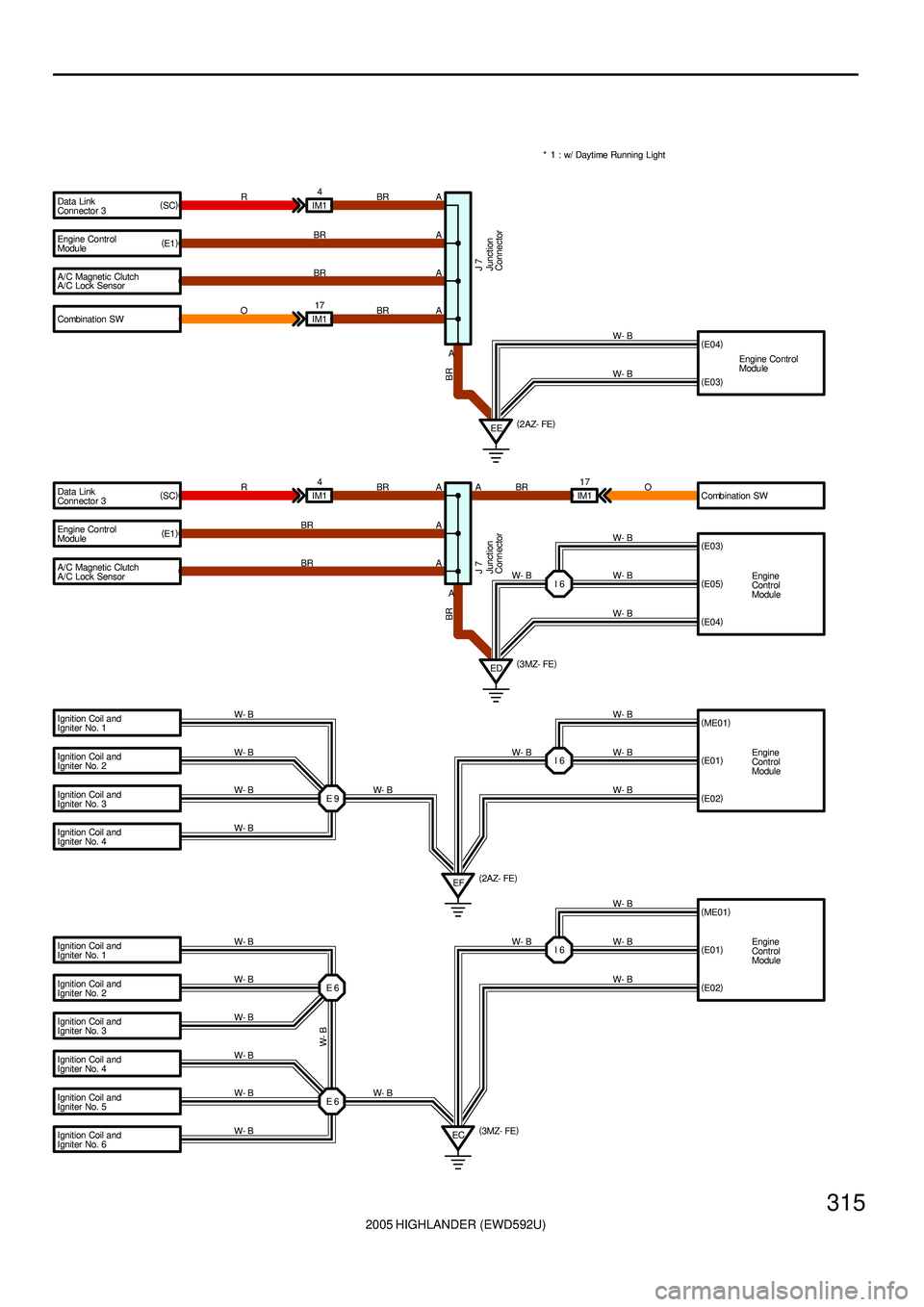
Data Link
Connector 3
Engine Contr ol
Module
A/C Magnetic Clutch
Combination SW Data Link
Connector 3
Ignition Coil and
Igniter No. 1A
A
A
A
A
ED A IM14
RBR
BR
R
BR
BR
J 7I 6W- B
W- B
W- B Engine Contr ol
Module
A/C Magnetic Clutch
A/C Lock Sensor
Ignition Coil and
Igniter No. 4 Ignition Coil and
Igniter No. 3 Ignition Coil and
Igniter No. 2 Ignition Coil and
Igniter No. 1IM14
BR
E 9
EF W- B W- B
W- B
W- B
W- BW- B
W- B A BR
A
A
EEEngine Contr ol
Module W- B
(
E03)
J 7
* 1 : w/ Daytime Running Light
Ignition Coil and
Igniter No. 2
Ignition Coil and
Igniter No. 3
Ignition Coil and
Igniter No. 4
Ignition Coil and
Igniter No. 5
Ignition Coil and
Igniter No. 6E 6
E 6 W- B
W- B
W- B
W- B
W- B
W- B
W- B
ECW- B
W- B
W- B(
2 AZ- FE)
(
3 MZ- FE)
(
2AZ- FE)
(
3MZ- FE) (
SC)
(
E1)
BR
(
E1) (
SC)
(
E03)
Engine
Control
Module (
E05)
(
E04)
BR
(
E01)
(
E02)
(
E01)
(
E02) IM117
OBR
A Combination SW
IM117
O BR(
E04)
W- B
W- B
Engine
Control
Module (
ME01)
W- B
I 6W- B
Engine
Control
Module (
ME01)
W- B
I 6W- B
Junction
ConnectorJunction
Connector
A/C Lock Sensor
Page 2154 of 2572

2005 HIGHLANDER (EWD592U)
317
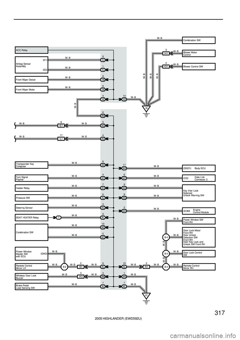
Turn Signal
Flasher
Heater Relay
Pr essure SW
Steer ing Sensor
SEAT HEATER Relay
Combination SW
Power Window
Master SW
with ECU
Remote Control
Mir ror LH Transponder Key
Computer
Body ECU
Data Link
Connector 3
Key Inter Lock
Solenoid
Remote Control
Mirror RH Door Lock Control
SW Power Window SW
Fron t RH
Door Unlock
Detection SW
Fron t RH
Wireless Door Lock
Buzzer
Br ake Pedal
Load Sensing SW4C44H11
4C6
4G9
4G8 4H7
4J6
4C3
4L9
4G10
4C5 W- B
W- B
W- B
W- B
W- B
W- B
W- B
W- BW- B
W- BW- B
W- B
W- B
B 2 I B 12
W- B
4L8
W- B
IK33
4M3
W- B
4J7 W- B
W- B4L 10 2
IN1 W- B
B 4W- B B 4 B 4
W- BW- B W- B
W- B
4N1
4L7
IC W- B
W- B(
GN D1)
(
CG)
4H5
W- B
W- B W- B
4D4
IL117
W- B W- B
4K8
W- B4D5
IE18
W- B W- B Air bag Sensor
Assembly
Front Wiper Deicer
Front Wiper Motor(
E1)
(
E2)1L9
1L1
1B9
1B8
1D14 W- B
W- B
W- B
W- B
W- B
W- B
W- B
W- B
Combination SW
Blower Motor
Control
Blower Control SW ACC Relay
IG12 W- B
W- B
W- B
IA 1E4
4M6
W- B
IH13
(
GN D)Engine
Control Module (
EOM)
1Unlock Warning SW
Door Lock Motor
Fron t RH
Door Key Lock and
Unlock SW Front RH
Page 2155 of 2572
2005 HIGHLANDER (EWD592U)
318
I GROUND POINT
Door Lock Motor
Rear RH
Power Window SW
Rear RH BC113
BC112
W- BW- B
BBW- B
W- B
Seat Heater SW RH BM11
W- BW- B
Stereo Power
Amplifier Wireless Door
Lock ECU Yaw Rate Sensor Char coal Canister
Assembly Rear Heater Blower
Motor Rear Heater Relay Rear Heater
Blower SWA
A
A
A
A
A
A
A BJ115 W- B
W- B
W- B
W- B
W- B W- B
W- B
W- B
W- B
BF
W- B
ARear Seat
Entertainment
ECU
(
SELD) (
GND)
J19
Occupant
Classification
ECU BL13
W- B W- B
W- B
W- B C
C
C
W- B
J18
C A
W- B
B A B A
A A Power Seat
Control SW
(
Front Passenger' s
Seat Contr ol)W- B
W- B W- B
(
*4)
(
*5) (
*5) (
*4) (
*4)* 4 : w/ Power Seat(
Front Passenger' s Seat)
* 5 : w/o Power Seat(
Front Passenger' s Seat)
(
E)(
GND) Door Unlock
Detection SW
Rear RH J23(
A)
, J24(
B)
Junction
Connector Junction
Connector
Junction Connector
Page 2161 of 2572
[A]
[B]
[H] [D]
[F] [E]
[ I ]
[L]
[M][J]
[K][G] [C]
1 2
IBIB
34
4 7
2111134
1 2
6 3
1 2
B18
BLRL
GR
B18 GR
3 4
Rear Combination Light RH R 7
Rear Combination Light LH R 6
High Mounted
Stop Light H17Light Failure Sensor Stop Light SW
ABS ECUS 6
Combination
Meter C 7
BV11
WB(Shielded) BV11I 5 GWIB 2IB 1
IE1 14
BO
50
8L 4 15A
STOP7.5A
GAUGE From Power Source System (See Page 66)
Stop Light
GR WB WB
WB
WBGB
YG RLR GR
WR GW WB
GW
W/ G)
(
S/D)
L L(
(
S/D)
Stop
Stop
Rear
Lights
2005 HIGHLANDER (EWD592U)
4
B HOW TO USE THIS MANUAL
*The system shown here is an EXAMPLE ONLY. It is different to the actual
circuit shown in the SYSTEM CIRCUITS SECTION.
Page 2163 of 2572
![TOYOTA HIGHLANDER 2001 Service Repair Manual [N]
[O]
[P]
[Q]
[R]
[S]
[T]
[U]
2005 HIGHLANDER (EWD592U)
6
B HOW TO USE THIS MANUAL
Current is applied at all times through the STOP fuse to TERMINAL 2 of the stop light SW.
When the ignition SW is TOYOTA HIGHLANDER 2001 Service Repair Manual [N]
[O]
[P]
[Q]
[R]
[S]
[T]
[U]
2005 HIGHLANDER (EWD592U)
6
B HOW TO USE THIS MANUAL
Current is applied at all times through the STOP fuse to TERMINAL 2 of the stop light SW.
When the ignition SW is](/manual-img/14/57457/w960_57457-2162.png)
[N]
[O]
[P]
[Q]
[R]
[S]
[T]
[U]
2005 HIGHLANDER (EWD592U)
6
B HOW TO USE THIS MANUAL
Current is applied at all times through the STOP fuse to TERMINAL 2 of the stop light SW.
When the ignition SW is turned on, current flows from the GAUGE fuse to TERMINAL 8 of the light failure sensor, and also flows
through the rear lights warning light to TERMINAL 4 of the light failure sensor.
Stop Light Disconnection Warning
When the ignition SW is turned on and the brake pedal is pressed (Stop light SW on), if the stop light circuit is open, the current
flowing from TERMINAL 7 of the light failure sensor to TERMINALS 1, 2 changes, so the light failure sensor detects the
disconnection and the warning circuit of the light failure sensor is activated.
As a result, the current flows from TERMINAL 4 of the light failure sensor to TERMINAL 11 to GROUND and turns the rear lights
warning light on. By pressing the brake pedal, the current flowing to TERMINAL 8 of the light failure sensor keeps the warning
circuit on and holds the warning light on until the ignition SW is turned off.
S6 Stop Light SW
2-1 : Closed with the brake pedal depressed
L4 Light Failure Sensor
1, 2, 7-Ground : Approx. 12 volts with the stop light SW on
4, 8-Ground : Approx. 12 volts with the ignition SW at ON position
11-Ground : Always continuity
: Parts Location
CodeSee PageCodeSee PageCodeSee Page
C734L436R737
H1736R637S635
: Relay Blocks
CodeSee PageRelay Blocks (Relay Block Location)
118R/B No.1 (Instrument Panel Brace LH)
: Junction Block and Wire Harness Connector
CodeSee PageJunction Block and Wire Harness (Connector Location)
IB20Instrument Panel Wire and Instrument Panel J/B (Lower Finish Panel)
3C22Instrument Panel Wire and J/B No.3 (Instrument Panel Brace LH)
: Connector Joining Wire Harness and Wire Harness
CodeSee PageJoining Wire Harness and Wire Harness (Connector Location)
IE142Floor Wire and Instrument Panel Wire (Left Kick Panel)
BV150Luggage Room Wire and Floor Wire (Luggage Room Left)
: Ground Points
CodeSee PageGround Points Location
BL50Under the Left Center Pillar
BO50Back Panel Center
: Splice Points
CodeSee PageWire Harness with Splice PointsCodeSee PageWire Harness with Splice Points
I544Cowl WireB1850Luggage Room Wire
System Outline
Service Hints
Page 2164 of 2572
![TOYOTA HIGHLANDER 2001 Service Repair Manual 2005 HIGHLANDER (EWD592U)
7
B
[N]: Explains the system outline.
[O]: Indicates values or explains the function for reference during troubleshooting.
[P]: Indicates the reference page showing the posit TOYOTA HIGHLANDER 2001 Service Repair Manual 2005 HIGHLANDER (EWD592U)
7
B
[N]: Explains the system outline.
[O]: Indicates values or explains the function for reference during troubleshooting.
[P]: Indicates the reference page showing the posit](/manual-img/14/57457/w960_57457-2163.png)
2005 HIGHLANDER (EWD592U)
7
B
[N]: Explains the system outline.
[O]: Indicates values or explains the function for reference during troubleshooting.
[P]: Indicates the reference page showing the position on the vehicle of the parts in the system circuit.
Example : Part ºL4º (Light Failure Sensor) is on page 36 of the manual.
*The letter in the code is from the first letter of the part, and the number indicates its order in parts
starting with that letter.
Example : L 4� �Parts is 4th in order
Light Failure Sensor
[Q]: Indicates the reference page showing the position on the vehicle of Relay Block Connectors in the system circuit.
Example : Connector º1º is described on page 18 of this manual and is installed on the left side of the instrument
panel.
[R]: Indicates the reference page showing the position on the vehicle of J/B and Wire Harness in the system circuit.
Example : Connector º3Cº connects the Instrument Panel Wire and J/B No.3. It is described on page 22 of this
manual, and is installed on the instrument panel left side.
[S]: Indicates the reference page describing the wiring harness and wiring harness connector (the female wiring
harness is shown first, followed by the male wiring harness).
Example : Connector ºIE1º connects the floor wire (female) and Instrument panel wire (male). It is described on
page 42 of this manual, and is installed on the left side kick panel.
[T]: Indicates the reference page showing the position of the ground points on the vehicle.
Example : Ground point ºBOº is described on page 50 of this manual and is installed on the back panel center.
[U]: Indicates the reference page showing the position of the splice points on the vehicle.
Example : Splice point ºI5º is on the Cowl Wire Harness and is described on page 44 of this manual.
Page 2168 of 2572

A 1
L PART NUMBER OF CONNECTORS
A/C Ambient Temp. Sensor Code
90980-1 1070Part Number
D 4 Diode (Courtesy) Code
90980-1 1608
A 2 A/C Condenser Fan Motor 90980-1 1237 D 5 Diode (Interior Light) 90980-10962
A 3 A/C Condenser Fan Relay 90980-10940 D 6 Diode (Moon Roof) 90980-1 1608
A 4 A/C Condenser Fan Resistor 90980-10928
90980-1 1271D 7 Door Lock Control Relay 90980-10848
A 5 A/C Magnetic Clutch
90980-1 1413D 8 Door Lock Control SW LH
90980-1 1148
A 6 A/T Oil Temp. Sensor
90980-1 1151D 9 Door Lock Control SW RH
A 7 ABS Actuator
90980-1 1009Door Courtesy SW LH
90980-1 1097
A 8 ABS Actuator
90980-10941Door Courtesy SW RH
A 9 ABS Speed Sensor Front LH
90980-1 1002Door Courtesy SW Front LH
ABS Speed Sensor Front RH
90980-1 1856Door Courtesy SW Front RH
90980-1 1156
Airbag Sensor Front LH Door Courtesy SW Rear LH
Airbag Sensor Front RH Door Courtesy SW Rear RH A10
A11
A12
A13 Airbag Squib 90980-1 1194 Door Key Lock and Unlock SW LH
90980-1 1170
90980-1 1070D10
D11
D12
D13
D14
D15
D16
D17 Door Key Lock and Unlock SW RHPart Number Part Name Part Name
[A]
[B] [C]
2005 HIGHLANDER (EWD592U)
11
B
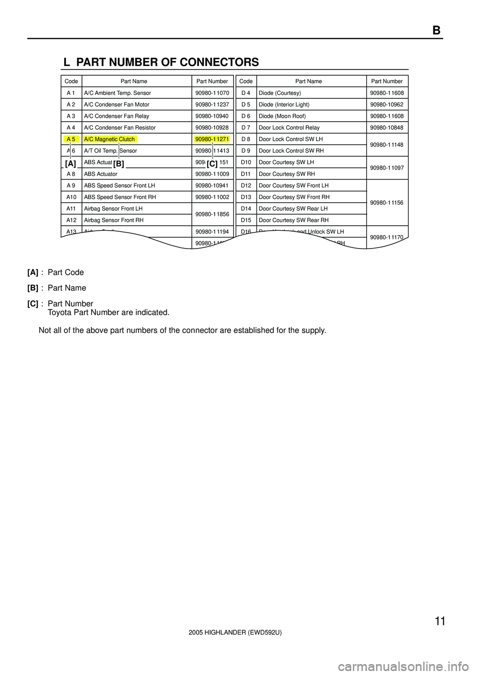
[A]: Part Code
[B]: Part Name
[C]: Part Number
Toyota Part Number are indicated.
Not all of the above part numbers of the connector are established for the supply.
Page 2177 of 2572

A01037
- ENGINE MECHANICALENGINE (2AZ-FE)
14-3
2496 Author�: Date�:
2005 HIGHLANDER REPAIR MANUAL (RM1144U)
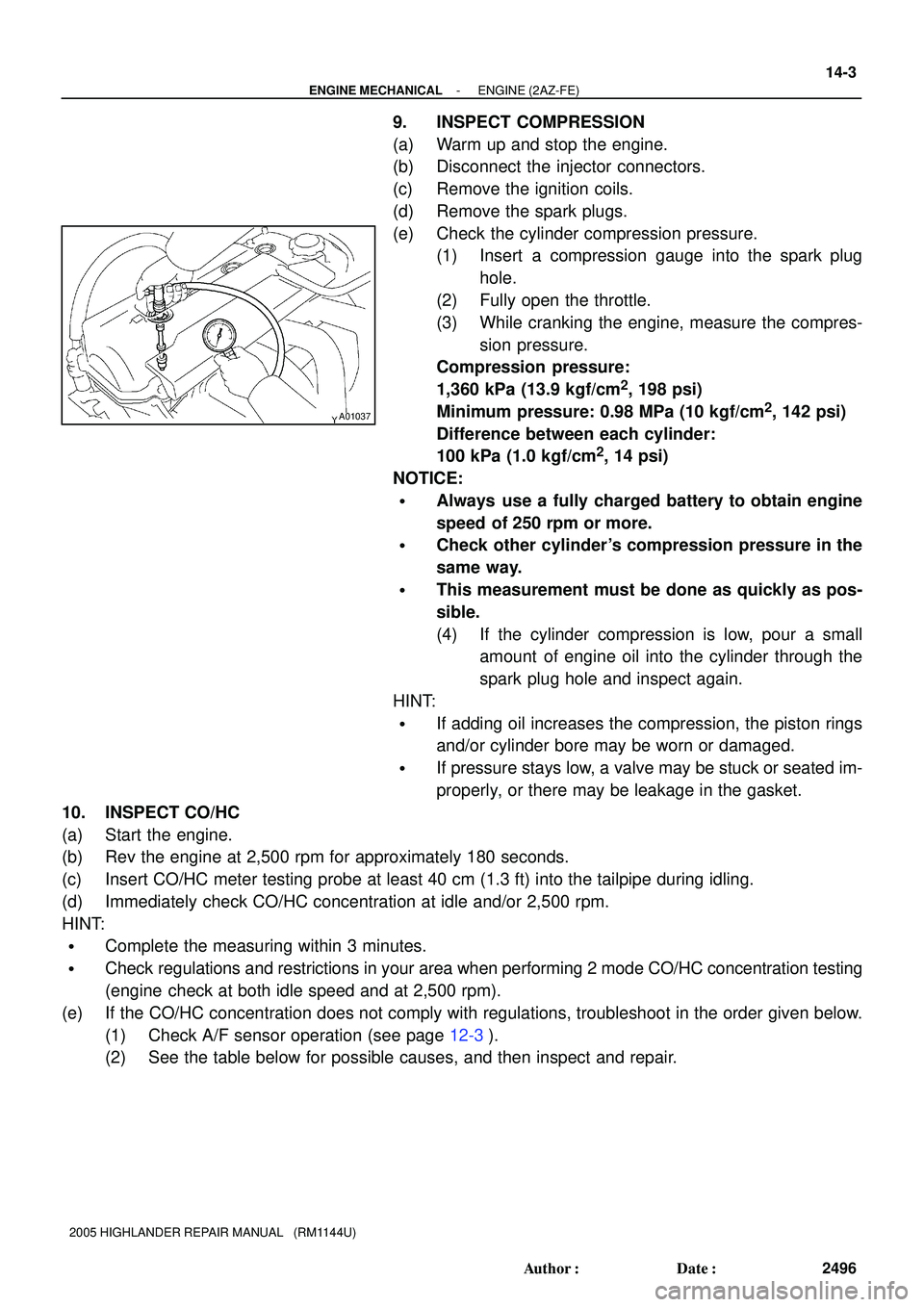
9. INSPECT COMPRESSION
(a) Warm up and stop the engine.
(b) Disconnect the injector connectors.
(c) Remove the ignition coils.
(d) Remove the spark plugs.
(e) Check the cylinder compression pressure.
(1) Insert a compression gauge into the spark plug
hole.
(2) Fully open the throttle.
(3) While cranking the engine, measure the compres-
sion pressure.
Compression pressure:
1,360 kPa (13.9 kgf/cm
2, 198 psi)
Minimum pressure: 0.98 MPa (10 kgf/cm
2, 142 psi)
Difference between each cylinder:
100 kPa (1.0 kgf/cm
2, 14 psi)
NOTICE:
�Always use a fully charged battery to obtain engine
speed of 250 rpm or more.
�Check other cylinder's compression pressure in the
same way.
�This measurement must be done as quickly as pos-
sible.
(4) If the cylinder compression is low, pour a small
amount of engine oil into the cylinder through the
spark plug hole and inspect again.
HINT:
�If adding oil increases the compression, the piston rings
and/or cylinder bore may be worn or damaged.
�If pressure stays low, a valve may be stuck or seated im-
properly, or there may be leakage in the gasket.
10. INSPECT CO/HC
(a) Start the engine.
(b) Rev the engine at 2,500 rpm for approximately 180 seconds.
(c) Insert CO/HC meter testing probe at least 40 cm (1.3 ft) into the tailpipe during idling.
(d) Immediately check CO/HC concentration at idle and/or 2,500 rpm.
HINT:
�Complete the measuring within 3 minutes.
�Check regulations and restrictions in your area when performing 2 mode CO/HC concentration testing
(engine check at both idle speed and at 2,500 rpm).
(e) If the CO/HC concentration does not comply with regulations, troubleshoot in the order given below.
(1) Check A/F sensor operation (see page 12-3).
(2) See the table below for possible causes, and then inspect and repair.