Page 2178 of 2572
14-4
- ENGINE MECHANICALENGINE (2AZ-FE)
2497 Author�: Date�:
2005 HIGHLANDER REPAIR MANUAL (RM1144U)CO
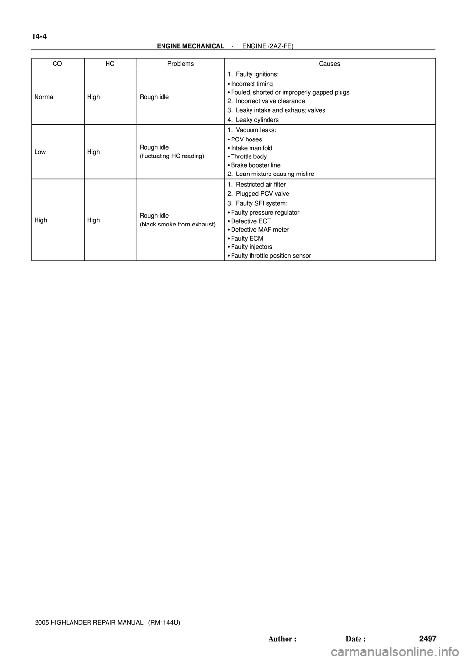
HCProblemsCauses
NormalHighRough idle
1. Faulty ignitions:
�Incorrect timing
�Fouled, shorted or improperly gapped plugs
2. Incorrect valve clearance
3. Leaky intake and exhaust valves
4. Leaky cylinders
LowHighRough idle
(fluctuating HC reading)
1. Vacuum leaks:
�PCV hoses
�Intake manifold
�Throttle body
�Brake booster line
2. Lean mixture causing misfire
HighHighRough idle
(black smoke from exhaust)
1. Restricted air filter
2. Plugged PCV valve
3. Faulty SFI system:
�Faulty pressure regulator
�Defective ECT
�Defective MAF meter
�Faulty ECM
�Faulty injectors
�Faulty throttle position sensor
Page 2181 of 2572

iv
2005 HIGHLANDER from Nov. 04 Prod. (OM48570U)
In order to be effective, the SRS airbags must deploy with
tremendous speed. The rapid deployment of the SRS air-
bags mak")
'05 HIGHLANDER_U (L/O 0409)
iv
2005 HIGHLANDER from Nov. '04 Prod. (OM48570U)
In order to be effective, the SRS airbags must deploy with
tremendous speed. The rapid deployment of the SRS air-
bags makes the SRS airbags themselves potential sources
of serious injury if an occupant is too close to an airbag,
or if an object or some part of his or her body has been
placed between the occupant and the airbag at the time of
deployment. This is just one example of how the instruc-
tions in Section 1- 3 of this Owner 's Manual will help en-
sure proper use of the occupant restraint systems, and
increase the safety they can provide to you and your fami-
ly in the event of an accident.
Toyota recommends you to read the provisions in Section
1- 3 carefully and refer to them as needed during your time
of ownership of this vehicle.Event data recorder
Your vehicle has computers that monitor and control cer-
tain aspects of your vehicle. These computers assist in
driving and maintaining optimal vehicle performance. Be-
sides storing data useful for troubleshooting, there is a
system to record data in a crash or a near car crash
event. This is called an Event Data Recorder (EDR).
The SRS airbag sensor assembly contains the EDR. In a
crash or a near car crash event, this device records some
or all of the following information:
�Engine speed
�Whether the brake pedal was applied or not
�Vehicle speed
�To what extent the accelerator pedal was depressed
�Position of the transmission selector lever
�Whether the driver and front passenger wore the seat
belts or not
�Driver 's seat position
�Front passenger 's occupant classification
Page 2190 of 2572

Resistance kW
30
20
10
5
2
1
0.5
0.3
0.2
0.13
-20 0 20 40 60 80 100
(-4)(32) (68) (140)(104) (212)
(176)
A91320
A65174
10-14
- ENGINE CONTROL")
1 2 3 4 5 6
A75258
M- M+ VTA VC VTA2 E2
Temperature�C (�F)
Resistance kW
30
20
10
5
2
1
0.5
0.3
0.2
0.13
-20 0 20 40 60 80 100
(-4)(32) (68) (140)(104) (212)
(176)
A91320
A65174
10-14
- ENGINE CONTROL SYSTEMSFI SYSTEM (3MZ-FE)
2372 Author�: Date�:
3. INSPECT ACCELERATOR PEDAL ROD ASSY
(a) Check the acceletor pedal position sensor (see page 05-469).
4. INSPECT THROTTLE BODY ASSY
(a) Check the throttle position sensor (see page 05-469).
(b) Check the throttle control motor.
(1) Measure the resistance between terminals 2 (M+)
and 1 (M-).
Resistance: 0.3 to 100 W at 20�C (68�F).
If the result is not as specified, replace the throttle body assy.
5. INSPECT ENGINE COOLANT TEMPERATURE
SENSOR
(a) Measure the resistance between each terminal.
Standard:
ConditionSpecified Condition
20�C (68�F)2.32 to 2.59 kW
80�C (176�F)0.310 to 0.326 kW
If the result is not as specified, replace the sensor.
NOTICE:
If checking the ECT sensor in the water, keep the terminals
dry. After the check, wipe the sensor dry.
6. INSPECT KNOCK SENSOR
(a) Measure the resistance between the terminals.
Resistance: 120 to 280 kW at 20�C (68�F)
If the result is not as specified, replace the sensor.
Page 2194 of 2572

TERMS
ABBREVIATIONS USED IN MANUAL
AbbreviationsMeaning
ABSAnti-Lock Brake System
A/CAir Conditioner
AC")
010QO-02
- INTRODUCTIONTERMS
01-41
41 Author�: Date�:
2005 HIGHLANDER REPAIR MANUAL (RM1144U)
TERMS
ABBREVIATIONS USED IN MANUAL
AbbreviationsMeaning
ABSAnti-Lock Brake System
A/CAir Conditioner
ACAlternating Current
ACCAccessory
ACISAcoustic Control Induction System
ACSDAutomatic Cold Start Device
A.D.D.Automatic Disconnecting Differential
A/FAir-Fuel Ratio
AHCActive Height Control Suspension
ALRAutomatic Locking Retractor
ALTAlternator
AMPAmplifier
ANTAntenna
Approx.Approximately
ASSYAssembly
A/T, ATMAutomatic Transmission
AT FAutomatic Transmission Fluid
AUTOAutomatic
AUXAuxiliary
AV GAverage
AV SAdaptive Variable Suspension
B+Battery Voltage
BABrake Assist
BACSBoost Altitude Compensation System
BATBattery
BDCBottom Dead Center
B/LBi-Level
B/SBore-Stroke Ratio
BTDCBefore Top Dead Center
BVSVBimetallic Vacuum Switching Valve
CANController Area Network
CBCircuit Breaker
CCoCatalytic Converter For Oxidation
CDCompact Disc
CFCornering Force
CGCenter Of Gravity
CHChannel
CKDComplete Knock Down
COMB.Combination
CPECoupe
CPSCombustion Pressure Sensor
CPUCentral Processing Unit
CRSChild Restraint System
CTRCenter
C/VCheck Valve
CVControl Valve
CWCurb Weight
DCDirect Current
Page 2196 of 2572
Abbreviations Meaning
H-FUSEHigh Current Fuse
HIHigh
HIDHigh Intensity Discharge (Head Lamp)
HSGHousing
HTHard Top")
- INTRODUCTIONTERMS
01-43
43 Author�: Date�:
2005 HIGHLANDER REPAIR MANUAL (RM1144U)Abbreviations Meaning
H-FUSEHigh Current Fuse
HIHigh
HIDHigh Intensity Discharge (Head Lamp)
HSGHousing
HTHard Top
HWSHeated Windshield System
ICIntegrated Circuit
IDIIndirect Diesel Injection
IFSIndependent Front Suspension
IGIgnition
IIAIntegrated Ignition Assembly
INIntake (Manifold, Valve)
INTIntermittent
I/PInstrument Panel
IRSIndependent Rear Suspension
ISCIdle Speed Control
J/BJunction Block
J/CJunction Connector
KDKick-Down
LANLocal Area Network
LBLiftback
LCDLiquid Crystal Display
LEDLight Emitting Diode
LHLeft-Hand
LHDLeft-Hand Drive
L/H/WLength, Height, Width
LLCLong-Life Coolant
LNGLiquified Natural Gas
LOLow
LPGLiquified Petroleum Gas
LSDLimited Slip Differential
LSP & PVLoad Sensing Proportioning And Bypass Valve
LSPVLoad Sensing Proportioning Valve
MAPManifold Absolute Pressure
MAX.Maximum
MICMicrophone
MILMalfunction Indicator Lamp
MIN.Minimum
MG1Motor Generator No.1
MG2Motor Generator No.2
MPMultipurpose
MPIMultipoint Electronic Injection
MPXMultiplex Communication System
M/T, MTMManual Transmission (Transaxle)
MTMount
MTGMounting
NNeutral
NANatural Aspiration
No.Number
O2SOxygen Sensor
O/DOverdrive
Page 2197 of 2572
Abbreviations Meaning
OEMOriginal Equipment Manufacturing
OHCOverhead Camshaft
OHVOverhead Valve
OPTOption
ORVROn-")
01-44
- INTRODUCTIONTERMS
44 Author�: Date�:
2005 HIGHLANDER REPAIR MANUAL (RM1144U)Abbreviations Meaning
OEMOriginal Equipment Manufacturing
OHCOverhead Camshaft
OHVOverhead Valve
OPTOption
ORVROn-board Refilling Vapor Recovery
O/SOversize
P & BVProportioning And Bypass Valve
PCSPower Control System
PCVPositive Crankcase Ventilation
PKBParking Brake
PPSProgressive Power Steering
PTCPositive Temperature Coefficient
PSPower Steering
PTOPower Take-Of f
P/WPower Window
R & PRack And Pinion
RAMRandom Access Memory
R/BRelay Block
RBSRecirculating Ball Type Steering
R/FReinforcement
RFSRigid Front Suspension
RHRight-Hand
RHDRight-Hand Drive
RLYRelay
ROMRead Only Memory
RrRear
RRSRigid Rear Suspension
RWDRear-Wheel Drive
SDNSedan
SENSensor
SICSStarting Injection Control System
SOCState Of Charge
SOHCSingle Overhead Camshaft
SPECSpecification
SPISingle Point Injection
SRSSupplemental Restraint System
SSMSpecial Service Materials
SSTSpecial Service Tools
STDStandard
STJCold-Start Fuel Injection
SWSwitch
SYSSystem
T/ATransaxle
TACHTachometer
TBIThrottle Body Electronic Fuel Injection
TCTurbocharger
TCCSTOYOTA Computer-Controlled System
TCVTiming Control Valve
TDCTop Dead Center
TEMP.Temperature
TEMSTOYOTA Electronic Modulated Suspension
Page 2200 of 2572

D25088
Same terminal as
a male terminal
D32093
CORRECTINCORRECT
D32094
INCORRECT
INCORRECT
INCORRECT
Z17004
C
SensorOPEN
1
2B
1
21
21
2A
Fig. 1
ECU
- INTRODUCTIONHOW TO TROUBLESHOOT ECU CONTROLLED
SYSTEMS01-37
37 Author�: Date�:
2005 HIGHLANDER REPAIR MANUAL (RM1144U)
(3) Checking the contact pressure of the terminal:
Prepare a spare male terminal. Insert it into a fe-
male terminal, and check for good tension when in-
serting and after full engagement.
(d) REPAIR METHOD OF CONNECTOR TERMINAL
(1) If there is any dirt on the terminal, clean the contact
point using an air gun or shop rag. Never polish the
contact point using sandpaper as the platings may
come off.
(2) If there is abnormal contact pressure, replace the
female terminal. If the male terminal is gold-plated
(gold color), use a gold-plated female terminal; if it
is silver-plated (silver color), use a silver-plated fe-
male terminal.
(3) Damaged, deformed, or corroded terminals should
be replaced. If the terminal will not lock into the
housing, the housing may have to be replaced.
(e) HANDLING OF WIRE HARNESS
(1) If removing a wire harness, check the wiring and
clamping before proceeding so that it can be re-
stored in the same way.
(2) Never twist, pull or slacken the wire harness more
than necessary.
(3) Never make the wire harness come into contact
with a high temperature part, rotating, moving, vi-
brating or sharp-edged parts. Avoid panel edges,
screw tips and similar sharp items.
(4) When installing parts, never pinch the wire harness.
(5) Never cut or break the cover of the wire harness. If
it is cut or broken, replace it or securely repair it with
vinyl tape.
2. CHECK OPEN CIRCUIT
(a) For an open circuit in the wire harness in Fig. 1, perform
a resistance check (step b) or a voltage check (step c).
Page 2201 of 2572

Z17005
Fig. 2
Sensor
C
BA
ECU
1
21
22 1
B04722
Fig. 3
Sensor
B2
A
1
21
2
21
C
B1
1
2ECU
Z17007
Fig. 4
Sensor
CBA
1
21
2
2 15V
5V
0V 01-38
- INTRODUCTIONHOW TO TROUBLESHOOT ECU CONTROLLED
SYSTEMS
38 Author�: Date�:
2005 HIGHLANDER REPAIR MANUAL (RM1144U)
(b) Check the resistance.
(1) Disconnect connectors A and C and measure the
resistance between them.
Resistance: Below 1 W
HINT:
Measure the resistance while lightly shaking the wire harness
vertically and horizontally.
Fig. 2:
Tester ConnectionSpecified Condition
Connector A terminal 1 -
Connector C terminal 110 kW or higher
Connector A terminal 2 -
Connector C terminal 2Below 1 kW
If your results match the examples above, an open circuit exists
between terminal 1 of connector A and terminal 1 of connector
C.
(2) Disconnect connector B and measure the resis-
tance between the connectors.
Fig. 3:
Tester ConnectionSpecified Condition
Connector A terminal 1 -
Connector B1 terminal 1Below 1 kW
Connector B2 terminal 1 -
Connector C terminal 110 kW or higher
If your results match the examples above, an open circuit exists
between terminal 1 of connector B2 and terminal 1 of connector
C.
(c) Check the voltage.
(1) In a circuit in which voltage is applied to the ECU
connector terminal, an open circuit can be checked
by conducting a voltage check.
Fig. 4:
With each connector still connected, measure the
voltage between the body ground these terminals
(in this order): 1) terminal 1 of connector A at the
ECU 5V output terminal, 2) terminal 1 of connector
B, and 3) terminal 1 of connector C.