2001 TOYOTA HIGHLANDER service
[x] Cancel search: servicePage 532 of 2572
2005 HIGHLANDER (EWD592U)
217
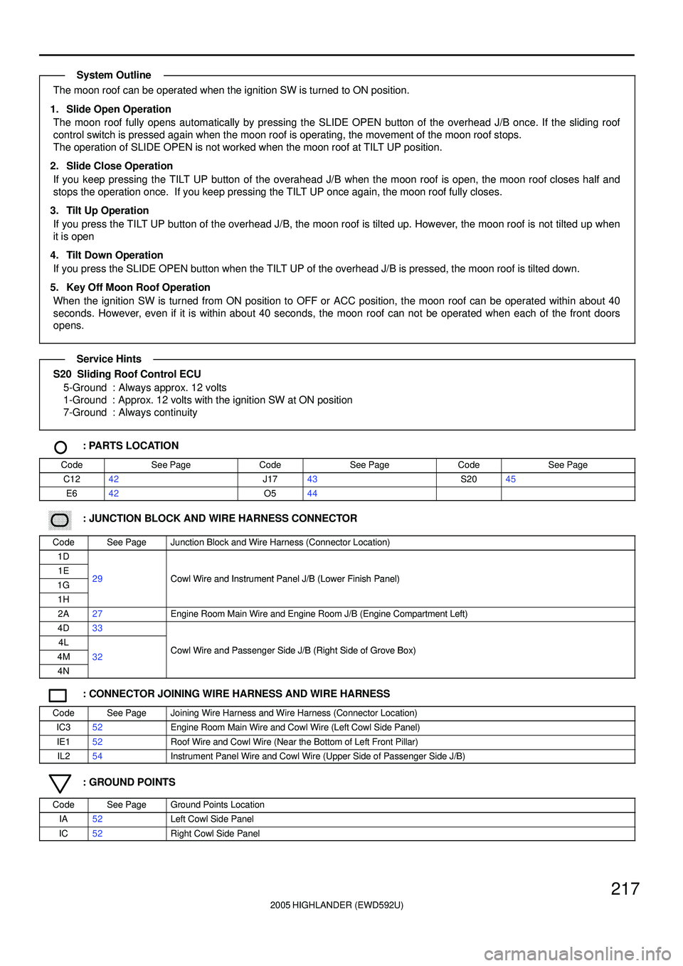
The moon roof can be operated when the ignition SW is turned to ON position.
1. Slide Open Operation
The moon roof fully opens automatically by pressing the SLIDE OPEN button of the overhead J/B once. If the sliding roof
control switch is pressed again when the moon roof is operating, the movement of the moon roof stops.
The operation of SLIDE OPEN is not worked when the moon roof at TILT UP position.
2. Slide Close Operation
If you keep pressing the TILT UP button of the overahead J/B when the moon roof is open, the moon roof closes half and
stops the operation once. If you keep pressing the TILT UP once again, the moon roof fully closes.
3. Tilt Up Operation
If you press the TILT UP button of the overhead J/B, the moon roof is tilted up. However, the moon roof is not tilted up when
it is open
4. Tilt Down Operation
If you press the SLIDE OPEN button when the TILT UP of the overhead J/B is pressed, the moon roof is tilted down.
5. Key Off Moon Roof Operation
When the ignition SW is turned from ON position to OFF or ACC position, the moon roof can be operated within about 40
seconds. However, even if it is within about 40 seconds, the moon roof can not be operated when each of the front doors
opens.
S20 Sliding Roof Control ECU
5-Ground : Always approx. 12 volts
1-Ground : Approx. 12 volts with the ignition SW at ON position
7-Ground : Always continuity
: PARTS LOCATION
CodeSee PageCodeSee PageCodeSee Page
C1242J1743S2045
E642O544
: JUNCTION BLOCK AND WIRE HARNESS CONNECTOR
CodeSee PageJunction Block and Wire Harness (Connector Location)
1D
1E29Cowl Wire and Instrument Panel J/B (Lower Finish Panel)1G29Cowl Wire and Instrument Panel J/B (Lower Finish Panel)
1H
2A27Engine Room Main Wire and Engine Room J/B (Engine Compartment Left)
4D33
4LCowl Wire and Passenger Side J/B (Right Side of Grove Box)4M32Cowl Wire and Passenger Side J/B (Right Side of Grove Box)
4N
: CONNECTOR JOINING WIRE HARNESS AND WIRE HARNESS
CodeSee PageJoining Wire Harness and Wire Harness (Connector Location)
IC352Engine Room Main Wire and Cowl Wire (Left Cowl Side Panel)
IE152Roof Wire and Cowl Wire (Near the Bottom of Left Front Pillar)
IL254Instrument Panel Wire and Cowl Wire (Upper Side of Passenger Side J/B)
: GROUND POINTS
CodeSee PageGround Points Location
IA52Left Cowl Side Panel
IC52Right Cowl Side Panel
System Outline
Service Hints
Page 536 of 2572
2005 HIGHLANDER (EWD592U)
221
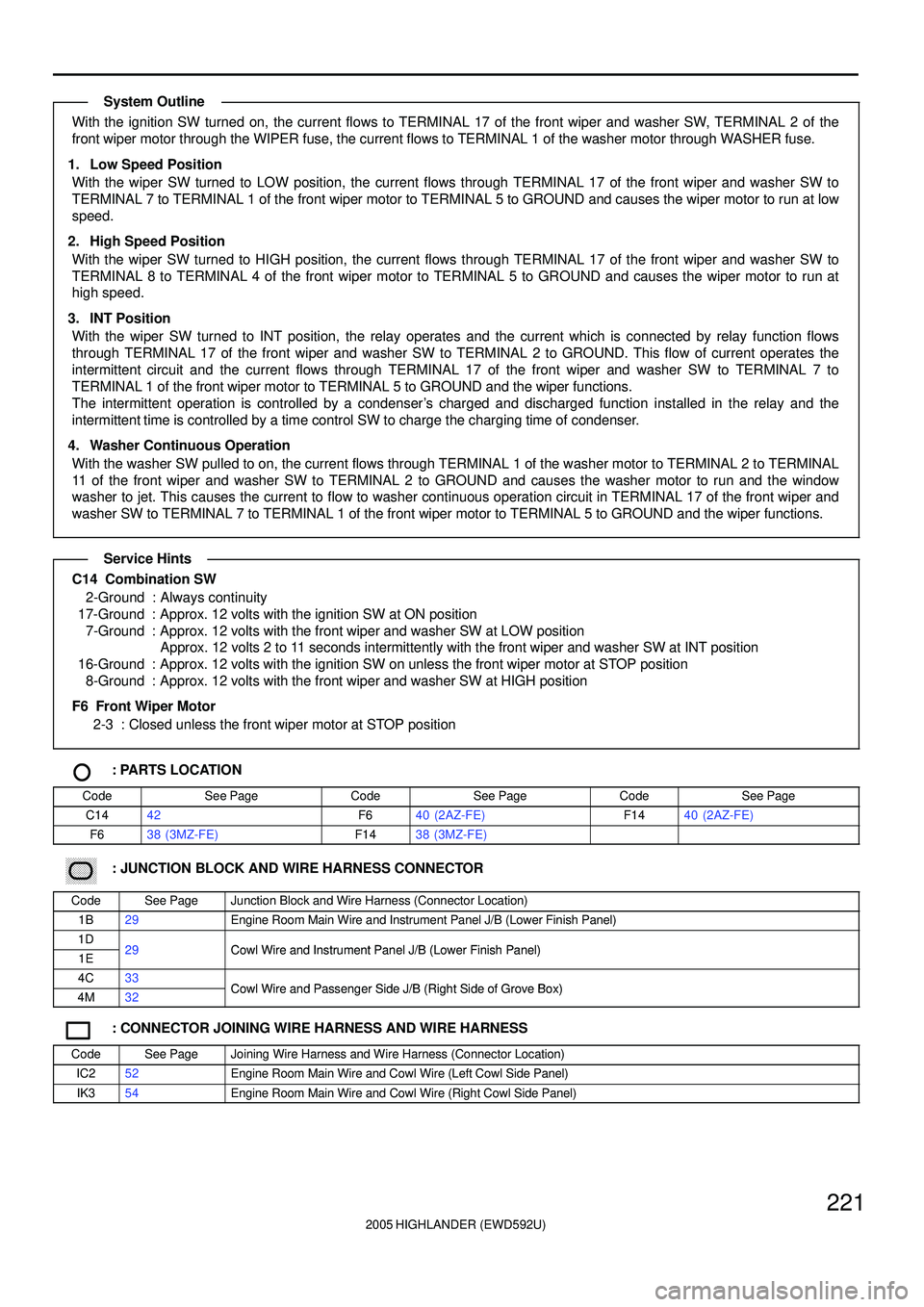
With the ignition SW turned on, the current flows to TERMINAL 17 of the front wiper and washer SW, TERMINAL 2 of the
front wiper motor through the WIPER fuse, the current flows to TERMINAL 1 of the washer motor through WASHER fuse.
1. Low Speed Position
With the wiper SW turned to LOW position, the current flows through TERMINAL 17 of the front wiper and washer SW to
TERMINAL 7 to TERMINAL 1 of the front wiper motor to TERMINAL 5 to GROUND and causes the wiper motor to run at low
speed.
2. High Speed Position
With the wiper SW turned to HIGH position, the current flows through TERMINAL 17 of the front wiper and washer SW to
TERMINAL 8 to TERMINAL 4 of the front wiper motor to TERMINAL 5 to GROUND and causes the wiper motor to run at
high speed.
3. INT Position
With the wiper SW turned to INT position, the relay operates and the current which is connected by relay function flows
through TERMINAL 17 of the front wiper and washer SW to TERMINAL 2 to GROUND. This flow of current operates the
intermittent circuit and the current flows through TERMINAL 17 of the front wiper and washer SW to TERMINAL 7 to
TERMINAL 1 of the front wiper motor to TERMINAL 5 to GROUND and the wiper functions.
The intermittent operation is controlled by a condenser's charged and discharged function installed in the relay and the
intermittent time is controlled by a time control SW to charge the charging time of condenser.
4. Washer Continuous Operation
With the washer SW pulled to on, the current flows through TERMINAL 1 of the washer motor to TERMINAL 2 to TERMINAL
11 of the front wiper and washer SW to TERMINAL 2 to GROUND and causes the washer motor to run and the window
washer to jet. This causes the current to flow to washer continuous operation circuit in TERMINAL 17 of the front wiper and
washer SW to TERMINAL 7 to TERMINAL 1 of the front wiper motor to TERMINAL 5 to GROUND and the wiper functions.
C14 Combination SW
2-Ground : Always continuity
17-Ground : Approx. 12 volts with the ignition SW at ON position
7-Ground : Approx. 12 volts with the front wiper and washer SW at LOW position
Approx. 12 volts 2 to 11 seconds intermittently with the front wiper and washer SW at INT position
16-Ground : Approx. 12 volts with the ignition SW on unless the front wiper motor at STOP position
8-Ground : Approx. 12 volts with the front wiper and washer SW at HIGH position
F6 Front Wiper Motor
2-3 : Closed unless the front wiper motor at STOP position
: PARTS LOCATION
CodeSee PageCodeSee PageCodeSee Page
C1442F640 (2AZ-FE)F1440 (2AZ-FE)
F638 (3MZ-FE)F1438 (3MZ-FE)
: JUNCTION BLOCK AND WIRE HARNESS CONNECTOR
CodeSee PageJunction Block and Wire Harness (Connector Location)
1B29Engine Room Main Wire and Instrument Panel J/B (Lower Finish Panel)
1D29Cowl Wire and Instrument Panel J/B (Lower Finish Panel)1E29Cowl Wire and Instrument Panel J/B (Lower Finish Panel)
4C33Cowl Wire and Passenger Side J/B (Right Side of Grove Box)4M32Cowl Wire and Passenger Side J/B (Right Side of Grove Box)
: CONNECTOR JOINING WIRE HARNESS AND WIRE HARNESS
CodeSee PageJoining Wire Harness and Wire Harness (Connector Location)
IC252Engine Room Main Wire and Cowl Wire (Left Cowl Side Panel)
IK354Engine Room Main Wire and Cowl Wire (Right Cowl Side Panel)
System Outline
Service Hints
Page 540 of 2572
2005 HIGHLANDER (EWD592U)
225
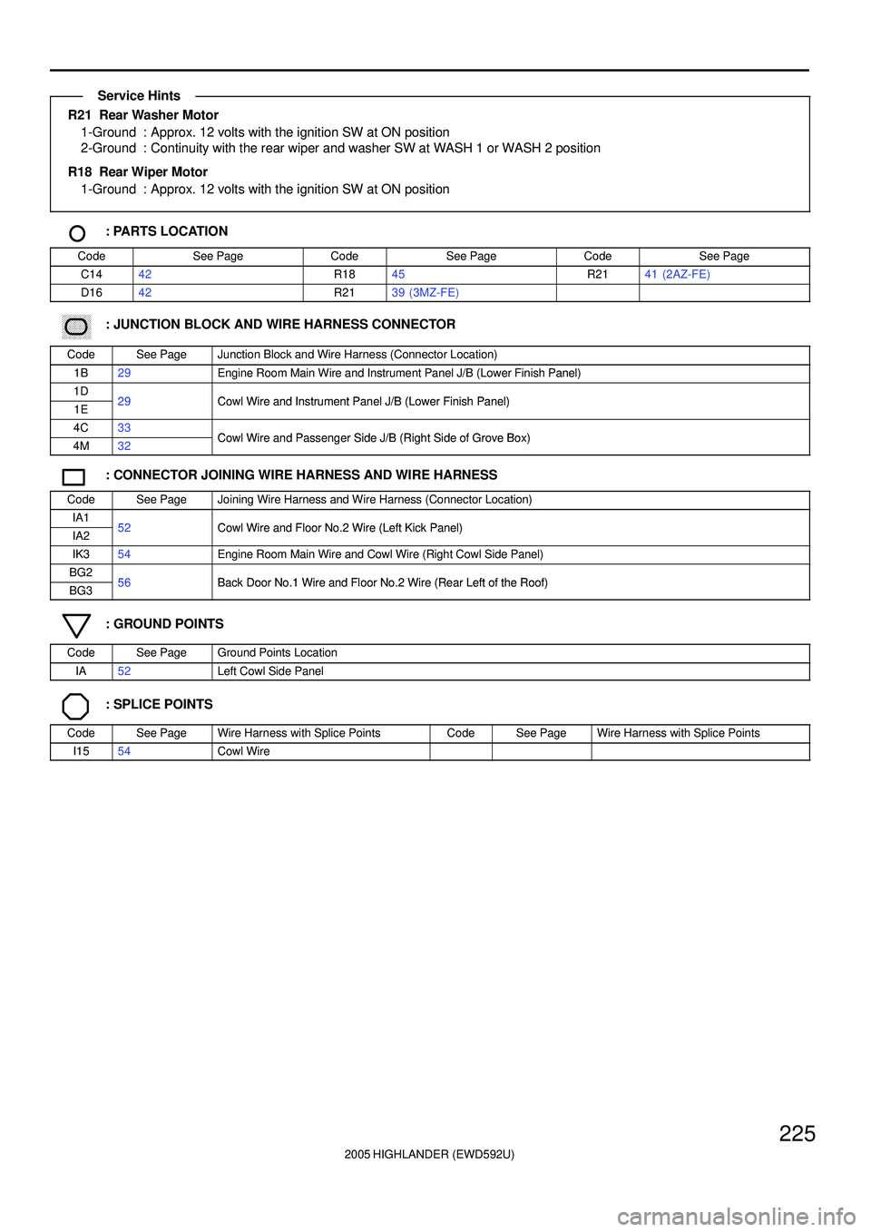
R21 Rear Washer Motor
1-Ground : Approx. 12 volts with the ignition SW at ON position
2-Ground : Continuity with the rear wiper and washer SW at WASH 1 or WASH 2 position
R18 Rear Wiper Motor
1-Ground : Approx. 12 volts with the ignition SW at ON position
: PARTS LOCATION
CodeSee PageCodeSee PageCodeSee Page
C1442R1845R2141 (2AZ-FE)
D1642R2139 (3MZ-FE)
: JUNCTION BLOCK AND WIRE HARNESS CONNECTOR
CodeSee PageJunction Block and Wire Harness (Connector Location)
1B29Engine Room Main Wire and Instrument Panel J/B (Lower Finish Panel)
1D29Cowl Wire and Instrument Panel J/B (Lower Finish Panel)1E29Cowl Wire and Instrument Panel J/B (Lower Finish Panel)
4C33Cowl Wire and Passenger Side J/B (Right Side of Grove Box)4M32Cowl Wire and Passenger Side J/B (Right Side of Grove Box)
: CONNECTOR JOINING WIRE HARNESS AND WIRE HARNESS
CodeSee PageJoining Wire Harness and Wire Harness (Connector Location)
IA152Cowl Wire and Floor No 2 Wire (Left Kick Panel)IA252Cowl Wire and Floor No.2 Wire (Left Kick Panel)
IK354Engine Room Main Wire and Cowl Wire (Right Cowl Side Panel)
BG256Back Door No 1 Wire and Floor No 2 Wire (Rear Left of the Roof)BG356Back Door No.1 Wire and Floor No.2 Wire (Rear Left of the Roof)
: GROUND POINTS
CodeSee PageGround Points Location
IA52Left Cowl Side Panel
: SPLICE POINTS
CodeSee PageWire Harness with Splice PointsCodeSee PageWire Harness with Splice Points
I1554Cowl Wire
Service Hints
Page 544 of 2572

2005 HIGHLANDER (EWD592U)
229
1. Seat Belt Warning System
When the ignition SW is turned to the ON position, the signal is input to the body ECU. At this time, to judge whether or not
the driver fastens the seat belt, the signal from the buckle SW LH is input to TERMINAL (A) 10 of the body ECU via multiplex
commnunication system (Bean bus). If the driver does not fasten the seat belt, the seat belt warning light in the combination
meter flashes and the alarm buzzer goes on, in response to the communication control of the body ECU etc.
Additionally, the sensor (Inside of buckle SW (Front passenger's side) ) installed on the front passenger seat detects the
passenger and determines whether or not the passenger fastens the seat belt.
If the passenger does not fasten the seat belt, the front passenger seat belt warning light is flashed.
2. Key Reminder System
If the driver door is opened with the ignition SW set at the ACC or OFF position and the ignition key remained inserted into
the key cylinder (The unlock warning SW is on), the signal from the unlock warning SW is input to TERMINAL (B) 2 of the
body ECU and the signal from the door courtesy SW LH is input to TERMINAL (C) 11 of body ECU. As a result, through
communication control of the body ECU etc. the buzzer in the combination meter goes on to warn the driver that the ignition
key is still inserted.
B19 Buckle SW LH
1-4 : Closed with the driver's seat belt in use
D7 Door Courtesy SW Front LH
1-Ground : Closed with the LH door open
K4 Unlock Warning SW
2-1 : Closed with the ignition key in the cylinder
B17 Buckle SW (Front Passenger's Side)
1-4 : Closed with the front passenger's seat belt in use
: PARTS LOCATION
CodeSee PageCodeSee PageCodeSee Page
A10A42B1747 (w/o Power Seat)O6A46 (w/ Power Seat)
A11B42B1946 (w/ Power Seat)O6A47 (w/o Power Seat)
A16A42B1947 (w/o Power Seat)O7B46 (w/ Power Seat)
A17B42C11A42O7B47 (w/o Power Seat)
A18C42C12B42O946 (w/ Power Seat)
B9A42D744O947 (w/o Power Seat)
B10B42E642P544
B11C42G543S30A43
B12D42J643S31B43
B1746 (w/ Power Seat)K443
System Outline
Service Hints
Page 548 of 2572
2005 HIGHLANDER (EWD592U)
233
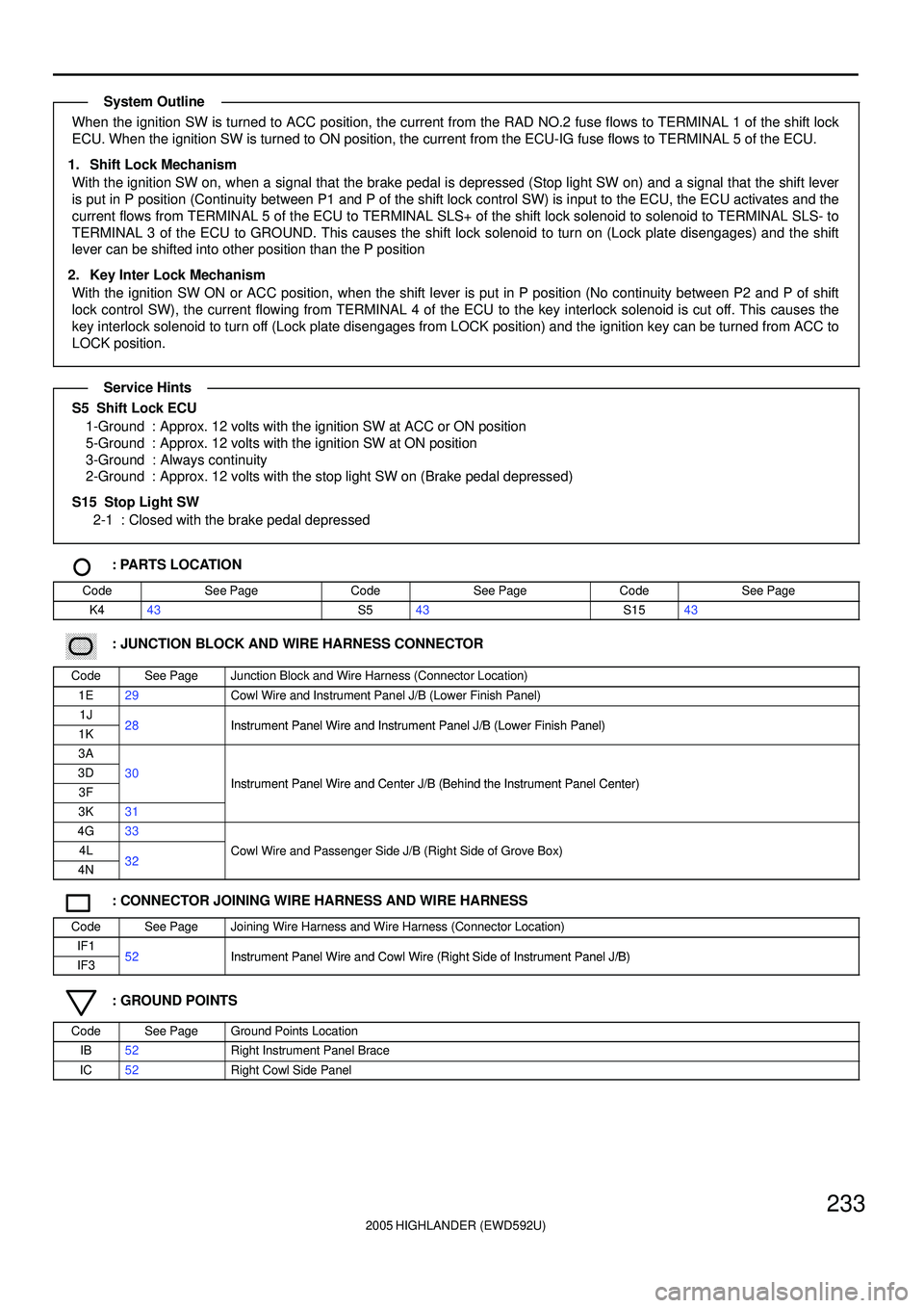
When the ignition SW is turned to ACC position, the current from the RAD NO.2 fuse flows to TERMINAL 1 of the shift lock
ECU. When the ignition SW is turned to ON position, the current from the ECU-IG fuse flows to TERMINAL 5 of the ECU.
1. Shift Lock Mechanism
With the ignition SW on, when a signal that the brake pedal is depressed (Stop light SW on) and a signal that the shift lever
is put in P position (Continuity between P1 and P of the shift lock control SW) is input to the ECU, the ECU activates and the
current flows from TERMINAL 5 of the ECU to TERMINAL SLS+ of the shift lock solenoid to solenoid to TERMINAL SLS- to
TERMINAL 3 of the ECU to GROUND. This causes the shift lock solenoid to turn on (Lock plate disengages) and the shift
lever can be shifted into other position than the P position
2. Key Inter Lock Mechanism
With the ignition SW ON or ACC position, when the shift lever is put in P position (No continuity between P2 and P of shift
lock control SW), the current flowing from TERMINAL 4 of the ECU to the key interlock solenoid is cut off. This causes the
key interlock solenoid to turn off (Lock plate disengages from LOCK position) and the ignition key can be turned from ACC to
LOCK position.
S5 Shift Lock ECU
1-Ground : Approx. 12 volts with the ignition SW at ACC or ON position
5-Ground : Approx. 12 volts with the ignition SW at ON position
3-Ground : Always continuity
2-Ground : Approx. 12 volts with the stop light SW on (Brake pedal depressed)
S15 Stop Light SW
2-1 : Closed with the brake pedal depressed
: PARTS LOCATION
CodeSee PageCodeSee PageCodeSee Page
K443S543S1543
: JUNCTION BLOCK AND WIRE HARNESS CONNECTOR
CodeSee PageJunction Block and Wire Harness (Connector Location)
1E29Cowl Wire and Instrument Panel J/B (Lower Finish Panel)
1J28Instrument Panel Wire and Instrument Panel J/B (Lower Finish Panel)1K28Instrument Panel Wire and Instrument Panel J/B (Lower Finish Panel)
3A
3D30Instrument Panel Wire and Center J/B (Behind the Instrument Panel Center)3FInstrument Panel Wire and Center J/B (Behind the Instrument Panel Center)
3K31
4G33
4L32Cowl Wire and Passenger Side J/B (Right Side of Grove Box)
4N32g(g )
: CONNECTOR JOINING WIRE HARNESS AND WIRE HARNESS
CodeSee PageJoining Wire Harness and Wire Harness (Connector Location)
IF152Instrument Panel Wire and Cowl Wire (Right Side of Instrument Panel J/B)IF352Instrument Panel Wire and Cowl Wire (Right Side of Instrument Panel J/B)
: GROUND POINTS
CodeSee PageGround Points Location
IB52Right Instrument Panel Brace
IC52Right Cowl Side Panel
System Outline
Service Hints
Page 551 of 2572
2005 HIGHLANDER (EWD592U)
236
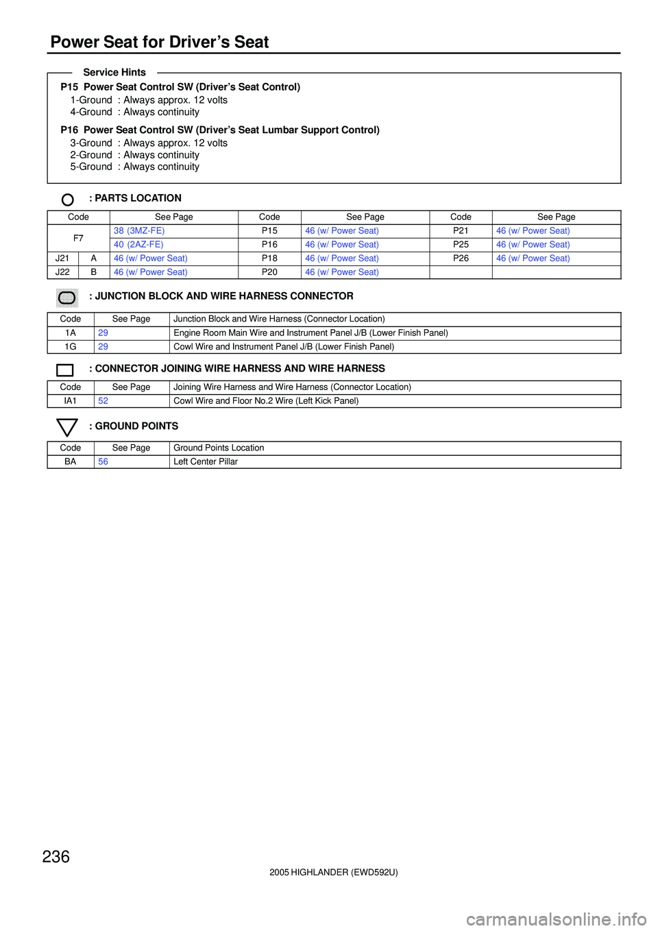
Power Seat for Driver's Seat
P15 Power Seat Control SW (Driver's Seat Control)
1-Ground : Always approx. 12 volts
4-Ground : Always continuity
P16 Power Seat Control SW (Driver's Seat Lumbar Support Control)
3-Ground : Always approx. 12 volts
2-Ground : Always continuity
5-Ground : Always continuity
: PARTS LOCATION
CodeSee PageCodeSee PageCodeSee Page
F738 (3MZ-FE)P1546 (w/ Power Seat)P2146 (w/ Power Seat)F740 (2AZ-FE)P1646 (w/ Power Seat)P2546 (w/ Power Seat)
J21A46 (w/ Power Seat)P1846 (w/ Power Seat)P2646 (w/ Power Seat)
J22B46 (w/ Power Seat)P2046 (w/ Power Seat)
: JUNCTION BLOCK AND WIRE HARNESS CONNECTOR
CodeSee PageJunction Block and Wire Harness (Connector Location)
1A29Engine Room Main Wire and Instrument Panel J/B (Lower Finish Panel)
1G29Cowl Wire and Instrument Panel J/B (Lower Finish Panel)
: CONNECTOR JOINING WIRE HARNESS AND WIRE HARNESS
CodeSee PageJoining Wire Harness and Wire Harness (Connector Location)
IA152Cowl Wire and Floor No.2 Wire (Left Kick Panel)
: GROUND POINTS
CodeSee PageGround Points Location
BA56Left Center Pillar
Service Hints
Page 554 of 2572
2005 HIGHLANDER (EWD592U)
239
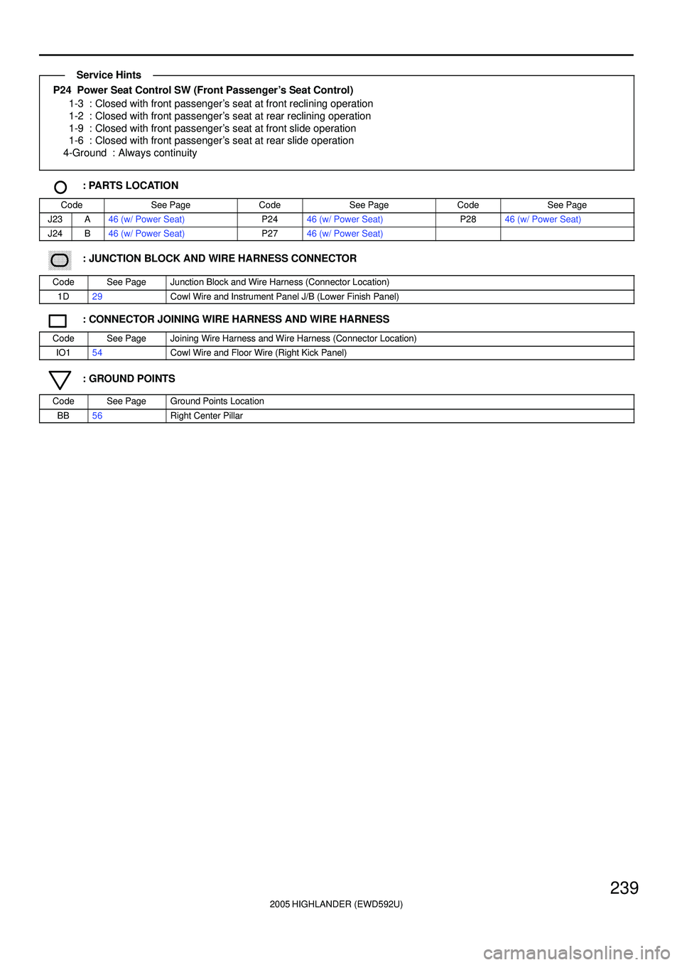
P24 Power Seat Control SW (Front Passenger's Seat Control)
1-3 : Closed with front passenger's seat at front reclining operation
1-2 : Closed with front passenger's seat at rear reclining operation
1-9 : Closed with front passenger's seat at front slide operation
1-6 : Closed with front passenger's seat at rear slide operation
4-Ground : Always continuity
: PARTS LOCATION
CodeSee PageCodeSee PageCodeSee Page
J23A46 (w/ Power Seat)P2446 (w/ Power Seat)P2846 (w/ Power Seat)
J24B46 (w/ Power Seat)P2746 (w/ Power Seat)
: JUNCTION BLOCK AND WIRE HARNESS CONNECTOR
CodeSee PageJunction Block and Wire Harness (Connector Location)
1D29Cowl Wire and Instrument Panel J/B (Lower Finish Panel)
: CONNECTOR JOINING WIRE HARNESS AND WIRE HARNESS
CodeSee PageJoining Wire Harness and Wire Harness (Connector Location)
IO154Cowl Wire and Floor Wire (Right Kick Panel)
: GROUND POINTS
CodeSee PageGround Points Location
BB56Right Center Pillar
Service Hints
Page 556 of 2572
2005 HIGHLANDER (EWD592U)
241
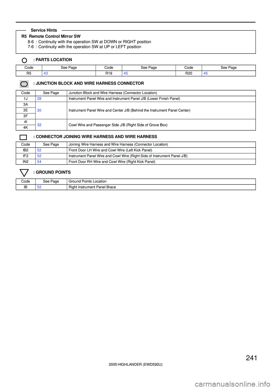
R5 Remote Control Mirror SW
8-6 : Continuity with the operation SW at DOWN or RIGHT position
7-6 : Continuity with the operation SW at UP or LEFT position
: PARTS LOCATION
CodeSee PageCodeSee PageCodeSee Page
R543R1945R2045
: JUNCTION BLOCK AND WIRE HARNESS CONNECTOR
CodeSee PageJunction Block and Wire Harness (Connector Location)
1J28Instrument Panel Wire and Instrument Panel J/B (Lower Finish Panel)
3A
3E30Instrument Panel Wire and Center J/B (Behind the Instrument Panel Center)
3F
()
4I32Cowl Wire and Passenger Side J/B (Right Side of Grove Box)4K32Cowl Wire and Passenger Side J/B (Right Side of Grove Box)
: CONNECTOR JOINING WIRE HARNESS AND WIRE HARNESS
CodeSee PageJoining Wire Harness and Wire Harness (Connector Location)
IB252Front Door LH Wire and Cowl Wire (Left Kick Panel)
IF252Instrument Panel Wire and Cowl Wire (Right Side of Instrument Panel J/B)
IN254Front Door RH Wire and Cowl Wire (Right Kick Panel)
: GROUND POINTS
CodeSee PageGround Points Location
IB52Right Instrument Panel Brace
Service Hints