2001 TOYOTA HIGHLANDER service
[x] Cancel search: servicePage 326 of 2572

2005 HIGHLANDER (EWD592U)
107
Previous automatic transaxle have selected each gear shift using mechanically controlled throttle hydraulic pressure,
governor hydraulic pressure and lock-up hydraulic pressure. The electronically controlled transmission, however, electrically
controls the line pressure, throttle pressure, lock-up pressure and accumulator pressure etc. through the solenoid valve. The
electronically controlled transmission is a system which precisely controls gear shift timing and lock-up timing in response to
the vehicle's driving conditions and the engine condition detected by various sensors. It makes smooth driving possible by
shift selection for each gear which is the most appropriate to the driving conditions at that time, and by preventing downing,
squat and gear shift shock when starting off.
1. Gear Shift Operation
During driving the engine warm up condition signal is input from engine coolant temp. sensor to TERMINAL THW of the
engine control module, and the vehicle speed signal is input from the ABS speed sensor to skid control ECU, and are sent to
the engine control module through communication control. At the same time, the throttle valve opening signal is sent from
the throttle position sensor to the TERMINALS VTA1 and VTA2 of the engine control module, as the throttle angle signal.
2. Lock-Up Operation
When the engine control module decides based on each signal that the lock-up condition has been met, the current flows
through TERMINAL DSL of the engine control module to TERMINAL 10 of the electronically controlled transmission solenoid
to GROUND.
3. Stop Light SW Circuit
If the brake pedal is depressed (Stop light SW on) when driving in lock-up condition, a signal is input to TERMINAL STP of
the engine control module. The engine control module operates and cuts the current to the solenoid to release lock-up.
4. Overdrive Circuit
*O/D main SW on
When the O/D main SW is turned on, a signal is input to TERMINAL ODMS of the engine control module and engine
control module operation causes gear shift when the conditions for overdrive are met.
*O/D main SW off
When the O/D main SW is turned off, a signal is input into TERMINAL ODMS of the engine control module, and turns on
the O/D off indicator light. This activates the ECU, and the transmission system is controlled not to shift to overdrive.
E4 Electronically Controlled Transmission Pattern Select SW
3-4 : Closed with the select SW at SNOW position
E5 (A), E6 (B), E7 (E), E8 (D), E9 (C) Engine Control Module
BATT-E1 : Always approx. 12 volts
MREL-E1 : Approx. 12 volts with the ignition SW ON position
P1 A/T Indicator SW
2-6 : Closed with the shift lever in P position
2-1 : Closed with the shift lever in R position
2-9 : Closed with the shift lever in N position
2-7 : Closed with the shift lever in D position
2-3 : Closed with the shift lever in 2 position
2-8 : Closed with the shift lever in L position
: PARTS LOCATION
CodeSee PageCodeSee PageCodeSee Page
A10A42E5A42P544
A11B42E6B42S1543
A1742E7E42S2739 (3MZ-FE)
B9A42E8D42S28A43
B10B42E9C42S29B43
C638 (3MZ-FE)G543S30A43
C11A42J239 (3MZ-FE)S31B43
C12B42J643T339 (3MZ-FE)
E138 (3MZ-FE)J743T1339 (3MZ-FE)
E238 (3MZ-FE)J1743T1643
E442P139 (3MZ-FE)
System Outline
Service Hints
Page 412 of 2572

2005 HIGHLANDER (EWD592U)
11 5
Previous automatic transaxle have selected each gear shift using mechanically controlled throttle hydraulic pressure,
governor hydraulic pressure and lock-up hydraulic pressure. The electronically controlled transmission, however, electrically
controls the line pressure, throttle pressure, lock-up pressure and accumulator pressure etc. through the solenoid valve. The
electronically controlled transmission is a system which precisely controls gear shift timing and lock-up timing in response to
the vehicle's driving conditions and the engine condition detected by various sensors. It makes smooth driving possible by
shift selection for each gear which is the most appropriate to the driving conditions at that time, and by preventing downing,
squat and gear shift shock when starting off.
1. Gear Shift Operation
During driving the engine warm up condition signal is input from engine coolant temp. sensor to TERMINAL THW of the
engine control module, and the vehicle speed signal is input from the ABS speed sensor to skid control ECU, and are sent to
the engine control module through communication control. At the same time, the throttle valve opening signal is sent from
the throttle position sensor to the TERMINALS VTA1 and VTA2 of the engine control module, as the throttle angle signal.
2. Lock-Up Operation
When the engine control module decides based on each signal that the lock-up condition has been met, the current flows
through TERMINAL DSL of the engine control module to TERMINAL 3 of the electronically controlled transmission solenoid
to GROUND.
3. Stop Light SW Circuit
If the brake pedal is depressed (Stop light SW on) when driving in lock-up condition, a signal is input to TERMINAL STP of
the engine control module. The engine control module operates and cuts the current to the solenoid to release lock-up.
4. Overdrive Circuit
*O/D main SW on
When the O/D main SW is turned on, a signal is input to TERMINAL ODMS of the engine control module and engine
control module operation causes gear shift when the conditions for overdrive are met.
*O/D main SW off
When the O/D main SW is turned off, a signal is input into TERMINAL ODMS of the engine control module, and turns on
the O/D off indicator light. This activates the ECU, and the transmission system is controlled not to shift to overdrive.
E4 Electronically Controlled Transmission Pattern Select SW
3-4 : Closed with the select SW at SNOW position
E5 (A), E6 (B), E7 (E), E8 (D), E9 (C) Engine Control Module
BATT-E1 : Always approx. 12 volts
MREL-E1 : Approx. 12 volts with the ignition SW ON position
P1 A/T Indicator SW
2-6 : Closed with the shift lever in P position
2-1 : Closed with the shift lever in R position
2-9 : Closed with the shift lever in N position
2-7 : Closed with the shift lever in D position
2-3 : Closed with the shift lever in 2 position
2-8 : Closed with the shift lever in L position
: PARTS LOCATION
CodeSee PageCodeSee PageCodeSee Page
A10A42E6B42S1543
A11B42E7E42S2741 (2AZ-FE)
A1742E8D42S28A43
B9A42E9C42S29B43
B10B42E1040 (2AZ-FE)S30A43
C640 (2AZ-FE)G543S31B43
C11A42J241 (2AZ-FE)T341 (2AZ-FE)
C12B42J643T1341 (2AZ-FE)
E240 (2AZ-FE)J743T1643
E442P141 (2AZ-FE)
E5A42P544
System Outline
Service Hints
Page 418 of 2572

'05 HIGHLANDER_U (L/O 0409)
250
2005 HIGHLANDER from Nov. '04 Prod. (OM48570U)
Air intake selector
Press the button to select the air source.
1. RecirculateÐRecirculates the air inside
the vehicle.
2. FreshÐDraws outside air into the sys-
tem.
To prevent fogging up of the windshield,
the air intake mode may change automati-
cally to FRESH depending on the condi-
tion of the air conditioning system.A/Cº button
To turn on the air conditioning, press the
A/Cº button. The A/Cº button indicator
will come on. To turn the air conditioning
off, press the button again.
If the A/Cº button indicator flashes, there
is a problem in the air conditioning system
and the air conditioning automatically
shuts off. If this happens, take your ve-
hicle to a Toyota dealer for service.
Page 424 of 2572

'05 HIGHLANDER_U (L/O 0409)
256
2005 HIGHLANDER from Nov. '04 Prod. (OM48570U)
When the A/Cº button is not pressed in,
pressing another air flow button turns off
the air conditioning.
For details about air flow selector settings,
see ÐAir flow selector settingsº de-
scribed below.
Air intake selector
Press the button to select the air source.
1. RecirculateÐRecirculates the air inside
the vehicle.
2. FreshÐDraws outside air into the sys-
tem.
If the engine coolant temperature becomes
extremely high, RECIRCULATE mode will
automatically be selected. This is not a
malfunction. When the engine coolant tem-
perature is lowered, the previous mode
will resume.
To prevent fogging up of the windshield,
the air intake mode may change automati-
cally to FRESH depending on the condi-
tion of the air conditioning system.A/Cº button
To turn on the air conditioning, press the
A/Cº button. The A/Cº button indicator
will come on. To turn the air conditioning
off, press the button again.
If the A/Cº button indicator flashes, there
is a problem in the air conditioning system
and the air conditioning automatically
shuts off. If this happens, take your ve-
hicle to a Toyota dealer for service.
Page 435 of 2572
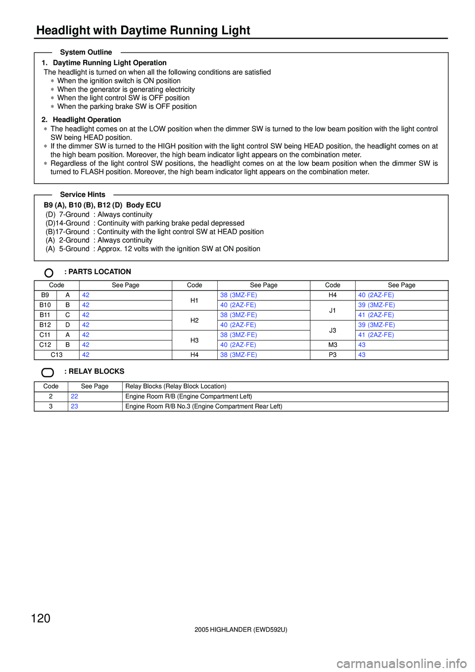
2005 HIGHLANDER (EWD592U)
120
Headlight with Daytime Running Light
1. Daytime Running Light Operation
The headlight is turned on when all the following conditions are satisfied
*When the ignition switch is ON position
*When the generator is generating electricity
*When the light control SW is OFF position
*When the parking brake SW is OFF position
2. Headlight Operation
*The headlight comes on at the LOW position when the dimmer SW is turned to the low beam position with the light control
SW being HEAD position.
*If the dimmer SW is turned to the HIGH position with the light control SW being HEAD position, the headlight comes on at
the high beam position. Moreover, the high beam indicator light appears on the combination meter.
*Regardless of the light control SW positions, the headlight comes on at the low beam position when the dimmer SW is
turned to FLASH position. Moreover, the high beam indicator light appears on the combination meter.
B9 (A), B10 (B), B12 (D) Body ECU
(D) 7-Ground : Always continuity
(D)14-Ground : Continuity with parking brake pedal depressed
(B)17-Ground : Continuity with the light control SW at HEAD position
(A) 2-Ground : Always continuity
(A) 5-Ground : Approx. 12 volts with the ignition SW at ON position
: PARTS LOCATION
CodeSee PageCodeSee PageCodeSee Page
B9A42H138 (3MZ-FE)H440 (2AZ-FE)
B10B42H140 (2AZ-FE)J139 (3MZ-FE)
B11C42H238 (3MZ-FE)J141 (2AZ-FE)
B12D42H240 (2AZ-FE)J339 (3MZ-FE)
C11A42H338 (3MZ-FE)J341 (2AZ-FE)
C12B42H340 (2AZ-FE)M343
C1342H438 (3MZ-FE)P343
: RELAY BLOCKS
CodeSee PageRelay Blocks (Relay Block Location)
222Engine Room R/B (Engine Compartment Left)
323Engine Room R/B No.3 (Engine Compartment Rear Left)
System Outline
Service Hints
Page 439 of 2572

2005 HIGHLANDER (EWD592U)
124
Headlight without Daytime Running Light
HEAD LAMP Relay
1-2 : Closed with the light control SW at HEAD position or dimmer SW at FLASH position
C13 Combination SW
13-16 : Closed with the light control SW at HEAD position
8-16 : Closed with the dimmer SW at FLASH position
7-16 : Closed with the dimmer SW at HIGH or FLASH position
: PARTS LOCATION
CodeSee PageCodeSee PageCodeSee Page
B9A42C1342H340 (2AZ-FE)
B10B42H138 (3MZ-FE)H438 (3MZ-FE)
B11C42H140 (2AZ-FE)H440 (2AZ-FE)
B12D42H238 (3MZ-FE)J339 (3MZ-FE)
C11A42H240 (2AZ-FE)J341 (2AZ-FE)
C12B42H338 (3MZ-FE)
: RELAY BLOCKS
CodeSee PageRelay Blocks (Relay Block Location)
222Engine Room R/B (Engine Compartment Left)
: JUNCTION BLOCK AND WIRE HARNESS CONNECTOR
CodeSee PageJunction Block and Wire Harness (Connector Location)
1G29Cowl Wire and Instrument Panel J/B (Lower Finish Panel)1H29Cowl Wire and Instrument Panel J/B (Lower Finish Panel)
1J28Instrument Panel Wire and Instrument Panel J/B (Lower Finish Panel)1K28Instrument Panel Wire and Instrument Panel J/B (Lower Finish Panel)
2A
2B27Engine Room Main Wire and Engine Room J/B (Engine Compartment Left)2F27Engine Room Main Wire and Engine Room J/B (Engine Compartment Left)
2G
3A
3B30Instrument Panel Wire and Center J/B (Behind the Instrument Panel Center)
3C
()
4A334F33
Cowl Wire and Passenger Side J/B (Right Side of Grove Box)4I32
Cowl Wire and Passenger Side J/B (Right Side of Grove Box)
4N32
: CONNECTOR JOINING WIRE HARNESS AND WIRE HARNESS
CodeSee PageJoining Wire Harness and Wire Harness (Connector Location)
IC252Engine Room Main Wire and Cowl Wire (Left Cowl Side Panel)IC352Engine Room Main Wire and Cowl Wire (Left Cowl Side Panel)
IF352Instrument Panel Wire and Cowl Wire (Right Side of Instrument Panel J/B)
IK354Engine Room Main Wire and Cowl Wire (Right Cowl Side Panel)
: GROUND POINTS
CodeSee PageGround Points Location
EA48 (3MZ-FE)Right Front Fender ApronEA50 (2AZ-FE)Right Front Fender Apron
IA52Left Cowl Side Panel
Service Hints
Page 442 of 2572

2005 HIGHLANDER (EWD592U)
127
FOG LIGHT Relay
3-5 : Closed with the light control SW at HEAD position, dimmer SW at LOW position and fog light SW on
: PARTS LOCATION
CodeSee PageCodeSee PageCodeSee Page
B9A42F138 (3MZ-FE)J139 (3MZ-FE)
B10B42F140 (2AZ-FE)J141 (2AZ-FE)
B12D42F238 (3MZ-FE)J339 (3MZ-FE)
C1342F240 (2AZ-FE)J341 (2AZ-FE)
: JUNCTION BLOCK AND WIRE HARNESS CONNECTOR
CodeSee PageJunction Block and Wire Harness (Connector Location)
1B29Engine Room Main Wire and Instrument Panel J/B (Lower Finish Panel)
1G29Cowl Wire and Instrument Panel J/B (Lower Finish Panel)1H29Cowl Wire and Instrument Panel J/B (Lower Finish Panel)
1J28Instrument Panel Wire and Instrument Panel J/B (Lower Finish Panel)1K28Instrument Panel Wire and Instrument Panel J/B (Lower Finish Panel)
2A27Engine Room Main Wire and Engine Room J/B (Engine Compartment Left)
3A30Instrument Panel Wire and Center J/B (Behind the Instrument Panel Center)3B30Instrument Panel Wire and Center J/B (Behind the Instrument Panel Center)
: CONNECTOR JOINING WIRE HARNESS AND WIRE HARNESS
CodeSee PageJoining Wire Harness and Wire Harness (Connector Location)
IC352Engine Room Main Wire and Cowl Wire (Left Cowl Side Panel)
: GROUND POINTS
CodeSee PageGround Points Location
EA48 (3MZ-FE)Right Front Fender ApronEA50 (2AZ-FE)Right Front Fender Apron
EG48 (3MZ-FE)Under the Left HeadlightEG50 (2AZ-FE)Under the Left Headlight
IA52Left Cowl Side Panel
: SPLICE POINTS
CodeSee PageWire Harness with Splice PointsCodeSee PageWire Harness with Splice Points
E1548 (3MZ-FE)Engine Room Main WireE1550 (2AZ-FE)Engine Room Main Wire
Service Hints
Page 444 of 2572

2005 HIGHLANDER (EWD592U)
129
TAILLIGHT Relay
5-3 : Closed with the light control SW at TAIL or HEAD position
C13 Combination SW
14-16 : Closed with the light control SW at TAIL or HEAD position
: PARTS LOCATION
CodeSee PageCodeSee PageCodeSee Page
B9A42F738 (3MZ-FE)J1344
B10B42F740 (2AZ-FE)J1444
C1342J139 (3MZ-FE)L144
F338 (3MZ-FE)J141 (2AZ-FE)R745F340 (2AZ-FE)J339 (3MZ-FE)R845
F438 (3MZ-FE)J341 (2AZ-FE)R1445F440 (2AZ-FE)J1244R1545
: JUNCTION BLOCK AND WIRE HARNESS CONNECTOR
CodeSee PageJunction Block and Wire Harness (Connector Location)
1A29Engine Room Main Wire and Instrument Panel J/B (Lower Finish Panel)1B29Engine Room Main Wire and Instrument Panel J/B (Lower Finish Panel)
1H29Cowl Wire and Instrument Panel J/B (Lower Finish Panel)
1J28Instrument Panel Wire and Instrument Panel J/B (Lower Finish Panel)
: CONNECTOR JOINING WIRE HARNESS AND WIRE HARNESS
CodeSee PageJoining Wire Harness and Wire Harness (Connector Location)
IA152Cowl Wire and Floor No.2 Wire (Left Kick Panel)
BG256Back Door No.1 Wire and Floor No.2 Wire (Rear Left of the Roof)
: GROUND POINTS
CodeSee PageGround Points Location
EA48 (3MZ-FE)Right Front Fender ApronEA50 (2AZ-FE)Right Front Fender Apron
EG48 (3MZ-FE)Under the Left HeadlightEG50 (2AZ-FE)Under the Left Headlight
IA52Left Cowl Side Panel
BC56Left Side of Rear Cross Member
BE56Left Side of Back Door
: SPLICE POINTS
CodeSee PageWire Harness with Splice PointsCodeSee PageWire Harness with Splice Points
B956Floor No.2 Wire
Service Hints