Page 1055 of 2572
05-1482
- DIAGNOSTICSSUPPLEMENTAL RESTRAINT SYSTEM
1672 Author�: Date�:
2005 HIGHLANDER REPAIR MANUAL (RM1144U)
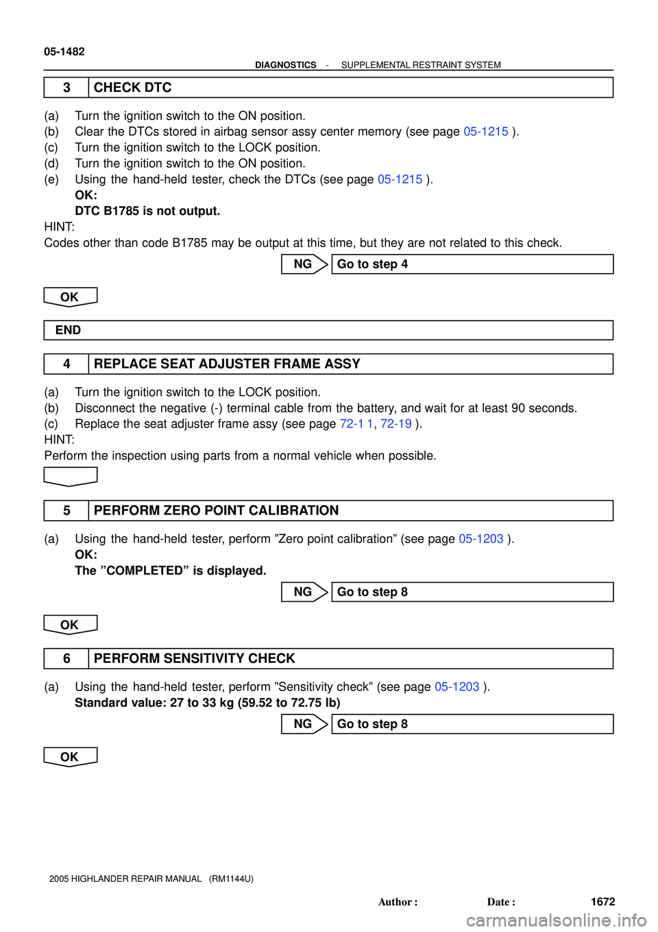
3 CHECK DTC
(a) Turn the ignition switch to the ON position.
(b) Clear the DTCs stored in airbag sensor assy center memory (see page 05-1215).
(c) Turn the ignition switch to the LOCK position.
(d) Turn the ignition switch to the ON position.
(e) Using the hand-held tester, check the DTCs (see page 05-1215).
OK:
DTC B1785 is not output.
HINT:
Codes other than code B1785 may be output at this time, but they are not related to this check.
NG Go to step 4
OK
END
4 REPLACE SEAT ADJUSTER FRAME ASSY
(a) Turn the ignition switch to the LOCK position.
(b) Disconnect the negative (-) terminal cable from the battery, and wait for at least 90 seconds.
(c) Replace the seat adjuster frame assy (see page 72-1 1, 72-19).
HINT:
Perform the inspection using parts from a normal vehicle when possible.
5 PERFORM ZERO POINT CALIBRATION
(a) Using the hand-held tester, perform ºZero point calibrationº (see page 05-1203).
OK:
The ºCOMPLETEDº is displayed.
NG Go to step 8
OK
6 PERFORM SENSITIVITY CHECK
(a) Using the hand-held tester, perform ºSensitivity checkº (see page 05-1203).
Standard value: 27 to 33 kg (59.52 to 72.75 lb)
NG Go to step 8
OK
Page 1058 of 2572
- DIAGNOSTICSSUPPLEMENTAL RESTRAINT SYSTEM
05-1485
1675 Author�: Date�:
2005 HIGHLANDER REPAIR MANUAL (RM1144U)
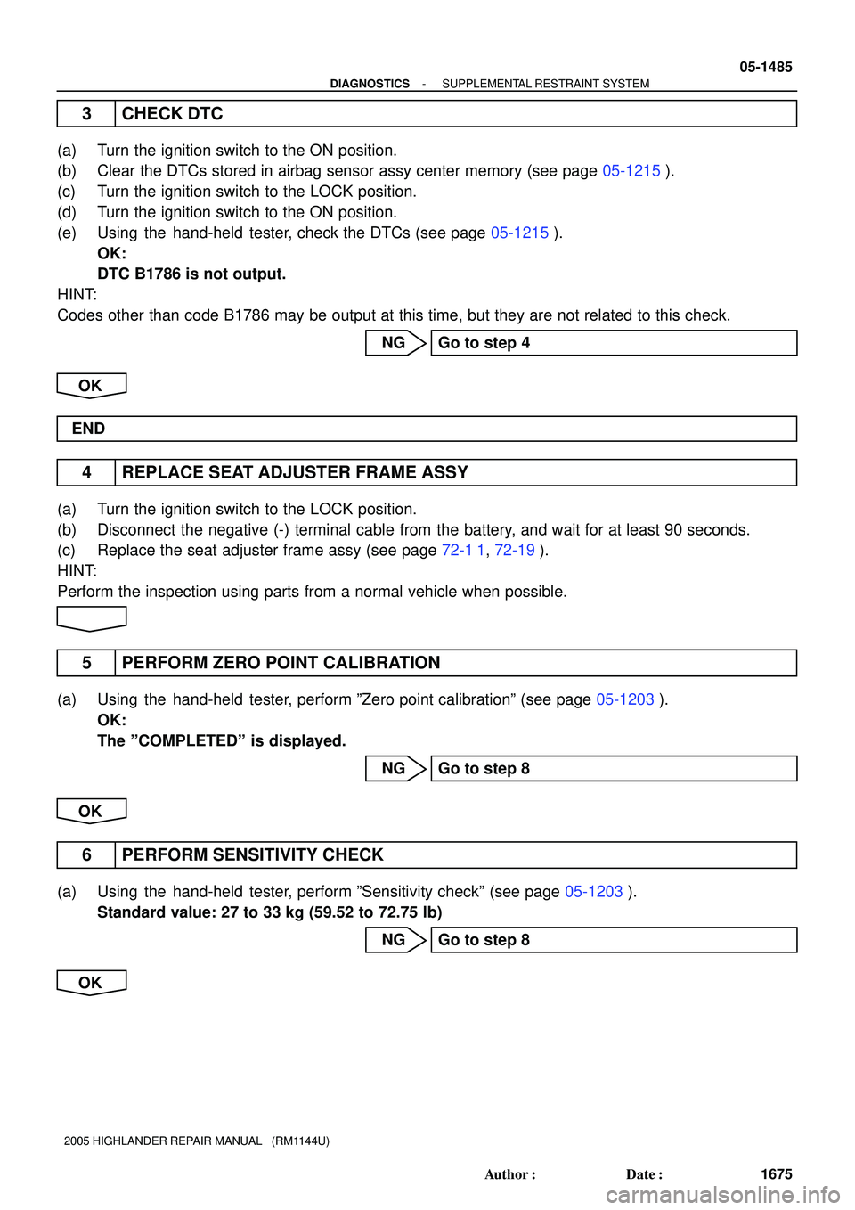
3 CHECK DTC
(a) Turn the ignition switch to the ON position.
(b) Clear the DTCs stored in airbag sensor assy center memory (see page 05-1215).
(c) Turn the ignition switch to the LOCK position.
(d) Turn the ignition switch to the ON position.
(e) Using the hand-held tester, check the DTCs (see page 05-1215).
OK:
DTC B1786 is not output.
HINT:
Codes other than code B1786 may be output at this time, but they are not related to this check.
NG Go to step 4
OK
END
4 REPLACE SEAT ADJUSTER FRAME ASSY
(a) Turn the ignition switch to the LOCK position.
(b) Disconnect the negative (-) terminal cable from the battery, and wait for at least 90 seconds.
(c) Replace the seat adjuster frame assy (see page 72-1 1, 72-19).
HINT:
Perform the inspection using parts from a normal vehicle when possible.
5 PERFORM ZERO POINT CALIBRATION
(a) Using the hand-held tester, perform ºZero point calibrationº (see page 05-1203).
OK:
The ºCOMPLETEDº is displayed.
NG Go to step 8
OK
6 PERFORM SENSITIVITY CHECK
(a) Using the hand-held tester, perform ºSensitivity checkº (see page 05-1203).
Standard value: 27 to 33 kg (59.52 to 72.75 lb)
NG Go to step 8
OK
Page 1061 of 2572
05-1488
- DIAGNOSTICSSUPPLEMENTAL RESTRAINT SYSTEM
1678 Author�: Date�:
2005 HIGHLANDER REPAIR MANUAL (RM1144U)
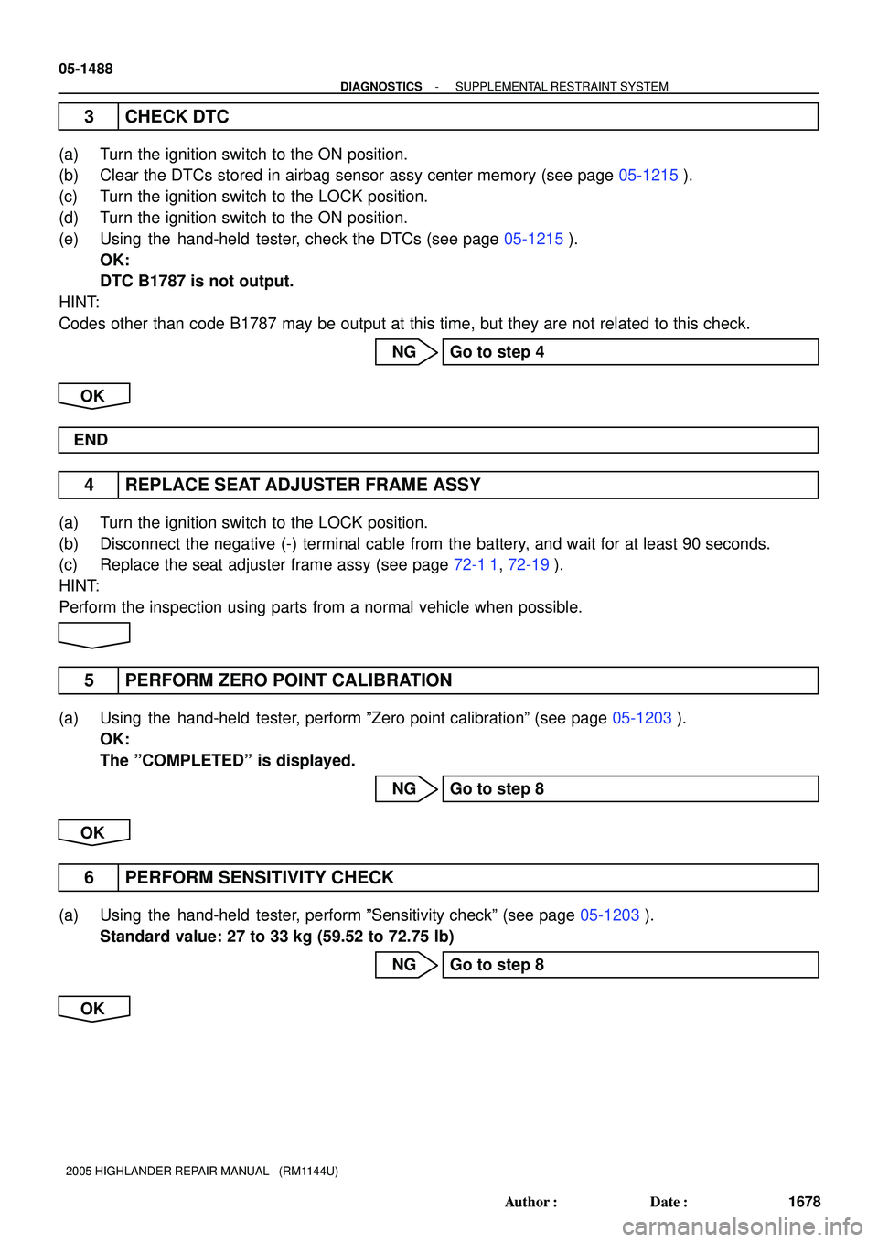
3 CHECK DTC
(a) Turn the ignition switch to the ON position.
(b) Clear the DTCs stored in airbag sensor assy center memory (see page 05-1215).
(c) Turn the ignition switch to the LOCK position.
(d) Turn the ignition switch to the ON position.
(e) Using the hand-held tester, check the DTCs (see page 05-1215).
OK:
DTC B1787 is not output.
HINT:
Codes other than code B1787 may be output at this time, but they are not related to this check.
NG Go to step 4
OK
END
4 REPLACE SEAT ADJUSTER FRAME ASSY
(a) Turn the ignition switch to the LOCK position.
(b) Disconnect the negative (-) terminal cable from the battery, and wait for at least 90 seconds.
(c) Replace the seat adjuster frame assy (see page 72-1 1, 72-19).
HINT:
Perform the inspection using parts from a normal vehicle when possible.
5 PERFORM ZERO POINT CALIBRATION
(a) Using the hand-held tester, perform ºZero point calibrationº (see page 05-1203).
OK:
The ºCOMPLETEDº is displayed.
NG Go to step 8
OK
6 PERFORM SENSITIVITY CHECK
(a) Using the hand-held tester, perform ºSensitivity checkº (see page 05-1203).
Standard value: 27 to 33 kg (59.52 to 72.75 lb)
NG Go to step 8
OK
Page 1064 of 2572
- DIAGNOSTICSSUPPLEMENTAL RESTRAINT SYSTEM
05-1491
1681 Author�: Date�:
2005 HIGHLANDER REPAIR MANUAL (RM1144U)
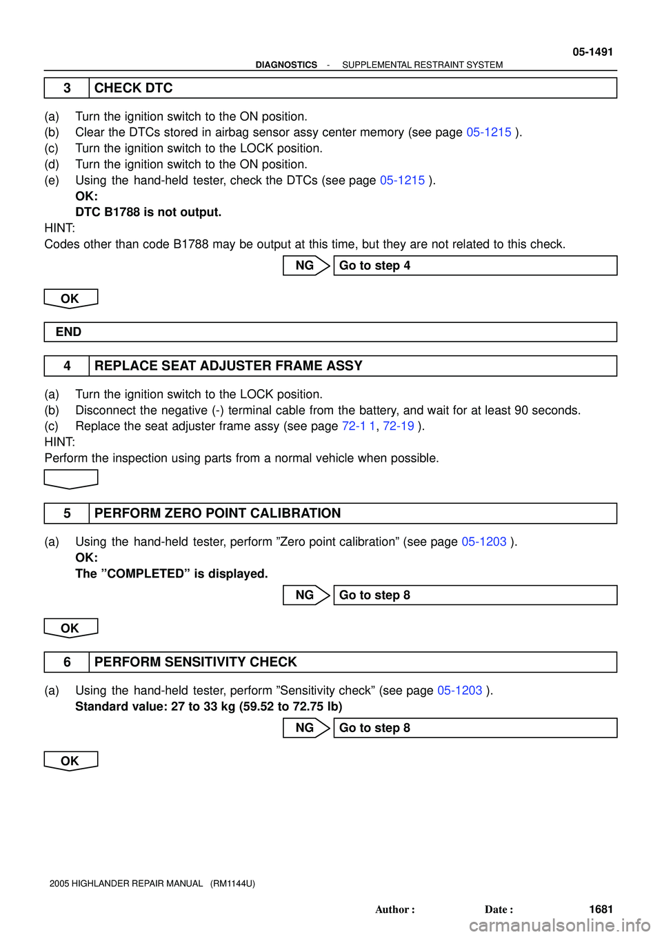
3 CHECK DTC
(a) Turn the ignition switch to the ON position.
(b) Clear the DTCs stored in airbag sensor assy center memory (see page 05-1215).
(c) Turn the ignition switch to the LOCK position.
(d) Turn the ignition switch to the ON position.
(e) Using the hand-held tester, check the DTCs (see page 05-1215).
OK:
DTC B1788 is not output.
HINT:
Codes other than code B1788 may be output at this time, but they are not related to this check.
NG Go to step 4
OK
END
4 REPLACE SEAT ADJUSTER FRAME ASSY
(a) Turn the ignition switch to the LOCK position.
(b) Disconnect the negative (-) terminal cable from the battery, and wait for at least 90 seconds.
(c) Replace the seat adjuster frame assy (see page 72-1 1, 72-19).
HINT:
Perform the inspection using parts from a normal vehicle when possible.
5 PERFORM ZERO POINT CALIBRATION
(a) Using the hand-held tester, perform ºZero point calibrationº (see page 05-1203).
OK:
The ºCOMPLETEDº is displayed.
NG Go to step 8
OK
6 PERFORM SENSITIVITY CHECK
(a) Using the hand-held tester, perform ºSensitivity checkº (see page 05-1203).
Standard value: 27 to 33 kg (59.52 to 72.75 lb)
NG Go to step 8
OK
Page 1068 of 2572
- DIAGNOSTICSSUPPLEMENTAL RESTRAINT SYSTEM
05-1495
1685 Author�: Date�:
2005 HIGHLANDER REPAIR MANUAL (RM1144U)
INSPECTION PROCEDURE
HINT:
�If troubleshooting (wire harness inspection) is difficult to perform, remove the front RH seat assy instal-
lation bolts to see the under surface of seat cushion.
�In the above case, hold the seat so that it does not fall down. Holding the seat for a long period of time
may cause a problem, such as seat rail deformation. Hold the seat only as necessary.
1 CHECK DTC
(a) Turn the ignition switch to the ON position.
(b) Clear the DTCs stored in memory (see page 05-1215).
HINT:
�First clear DTCs stored in the occupant classification ECU memory and then in the airbag sensor assy
center memory.
�Use the hand-held tester to clear the DTC of the occupant classification ECU, otherwise the DTC can-
not be cleared.
(c) Turn the ignition switch to the LOCK position.
(d) Turn the ignition switch to the ON position.
(e) Using the hand-held tester, check the DTCs (see page 05-1215).
OK:
DTC B1790 is not output.
HINT:
Codes other than code B1790 may be output at this time, but they are not related to this check.
NG Go to step 2
OK
USE SIMULATION METHOD TO CHECK (SEE PAGE 05-1207)
2 CHECK CONNECTION OF CONNECTORS
(a) Turn the ignition switch to the LOCK position.
(b) Disconnect the negative (-) terminal cable from the battery, and wait for at least 90 seconds.
(c) Check that the connectors are properly connected to the occupant classification ECU and the airbag
sensor assy center.
OK:
The connectors are connected.
NG CONNECT CONNECTORS, THEN GO TO STEP
1
OK
Page 1077 of 2572
05-1504
- DIAGNOSTICSSUPPLEMENTAL RESTRAINT SYSTEM
1694 Author�: Date�:
2005 HIGHLANDER REPAIR MANUAL (RM1144U)
INSPECTION PROCEDURE
HINT:
�If troubleshooting (wire harness inspection) is difficult to perform, remove the front RH seat assy instal-
lation bolts to see the under surface of seat cushion.
�In the above case, hold the seat so that it does not fall down. Holding the seat for a long period of time
may cause a problem, such as seat rail deformation. Hold the seat only as necessary.
1 CHECK DTC
(a) Turn the ignition switch to the ON position.
(b) Clear the DTCs stored in memory (see page 05-1215).
HINT:
�First clear DTCs stored in the occupant classification ECU memory and then in the airbag sensor assy
center memory.
�Use the hand-held tester to clear the DTC of the occupant classification ECU, otherwise the DTC can-
not be cleared.
(c) Turn the ignition switch to the LOCK position.
(d) Turn the ignition switch to the ON position.
(e) Using the hand-held tester, check the DTCs (see page 05-1215).
OK:
DTC B1793 is not output.
HINT:
Codes other than code B1793 may be output at this time, but they are not related to this check.
NG Go to step 2
OK
USE SIMULATION METHOD TO CHECK (SEE PAGE 05-1207)
2 CHECK CONNECTION OF CONNECTORS
(a) Turn the ignition switch to the LOCK position.
(b) Disconnect the negative (-) terminal cable from the battery, and wait for at least 90 seconds.
(c) Check that the connectors are properly connected to the occupant classification ECU and the occu-
pant classification sensors.
OK:
The connectors are connected.
NG CONNECT CONNECTORS, THEN GO TO STEP
1
OK
Page 1081 of 2572
05-1508
- DIAGNOSTICSSUPPLEMENTAL RESTRAINT SYSTEM
1698 Author�: Date�:
2005 HIGHLANDER REPAIR MANUAL (RM1144U)
10 PERFORM SENSITIVITY CHECK
(a) Using the hand-held tester, perform ºSensitivity checkº (see page 05-1203).
Standard value: 27 to 33 kg (59.52 to 72.75 lb)
NG Go to step 12
OK
11 RECHECK DTC
(a) Connect the negative (-) terminal cable to the battery.
(b) Turn the ignition switch to the ON position.
(c) Clear the DTCs stored in memory (see page 05-1215).
HINT:
�First clear DTCs stored in the occupant classification ECU memory and then in the airbag sensor assy
center memory.
�Use the hand-held tester to clear the DTC of the occupant classification ECU, otherwise the DTC can-
not be cleared.
(d) Turn the ignition switch to the LOCK position.
(e) Turn the ignition switch to the ON position.
(f) Using the hand-held tester, check the DTCs (see page 05-1215).
OK:
DTC B1793 is not output.
HINT:
Codes other than code B1793 may be output at this time, but they are related to this check.
NG Go to step 12
OK
END
12 REPLACE SEAT ADJUSTER FRAME ASSY
(a) Turn the ignition switch to the LOCK position.
(b) Disconnect the negative (-) terminal cable from the battery, and wait for at least 90 seconds.
(c) Replace the seat adjuster frame assy (see page 72-1 1, 72-19).
13 CHECK PERFORM ZERO POINT CALIBRATION
(a) Using the hand-held tester, perform ºZero point calibrationº (see page 05-1203).
OK:
The ºCOMPLETEDº is displayed.
Page 1144 of 2572
H10600 C91522H01007H10600 C91522H01007H42468
Airbag
Sensor
Assy
Center Seat
Position
Airbag
Sensor
DTC B1153/25 DLC3
CG
TC
- DIAGNOSTICSSUPPLEMENTAL RESTRAINT SYSTEM
05-1361
1551 Author�: Date�:
2005 HIGHLANDER REPAIR MANUAL (RM1144U)
INSPECTION PROCEDURE
1 CHECK DTC
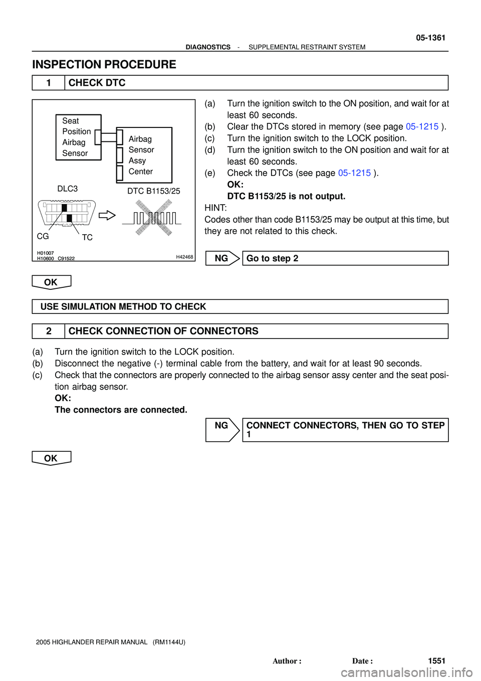
(a) Turn the ignition switch to the ON position, and wait for at
least 60 seconds.
(b) Clear the DTCs stored in memory (see page 05-1215).
(c) Turn the ignition switch to the LOCK position.
(d) Turn the ignition switch to the ON position and wait for at
least 60 seconds.
(e) Check the DTCs (see page 05-1215).
OK:
DTC B1153/25 is not output.
HINT:
Codes other than code B1153/25 may be output at this time, but
they are not related to this check.
NG Go to step 2
OK
USE SIMULATION METHOD TO CHECK
2 CHECK CONNECTION OF CONNECTORS
(a) Turn the ignition switch to the LOCK position.
(b) Disconnect the negative (-) terminal cable from the battery, and wait for at least 90 seconds.
(c) Check that the connectors are properly connected to the airbag sensor assy center and the seat posi-
tion airbag sensor.
OK:
The connectors are connected.
NG CONNECT CONNECTORS, THEN GO TO STEP
1
OK