Page 1539 of 2572
E72975
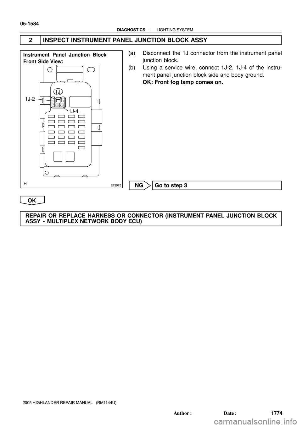
Instrument Panel Junction Block
Front Side View:
1J
1J-4 1J-2
05-1584
- DIAGNOSTICSLIGHTING SYSTEM
1774 Author�: Date�:
2005 HIGHLANDER REPAIR MANUAL (RM1144U)
2 INSPECT INSTRUMENT PANEL JUNCTION BLOCK ASSY
(a) Disconnect the 1J connector from the instrument panel
junction block.
(b) Using a service wire, connect 1J-2, 1J-4 of the instru-
ment panel junction block side and body ground.
OK: Front fog lamp comes on.
NG Go to step 3
OK
REPAIR OR REPLACE HARNESS OR CONNECTOR (INSTRUMENT PANEL JUNCTION BLOCK
ASSY - MULTIPLEX NETWORK BODY ECU)
Page 1540 of 2572
E72977
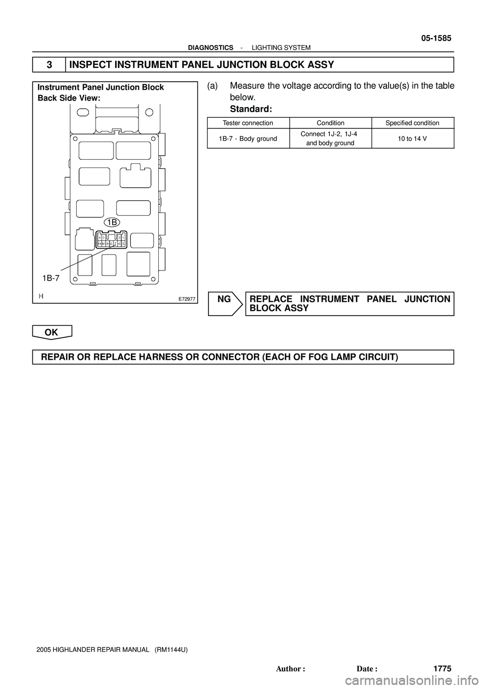
Instrument Panel Junction Block
Back Side View:
1B
1B-7
- DIAGNOSTICSLIGHTING SYSTEM
05-1585
1775 Author�: Date�:
2005 HIGHLANDER REPAIR MANUAL (RM1144U)
3 INSPECT INSTRUMENT PANEL JUNCTION BLOCK ASSY
(a) Measure the voltage according to the value(s) in the table
below.
Standard:
Tester connectionConditionSpecified condition
1B-7 - Body groundConnect 1J-2, 1J-4
and body ground10 to 14 V
NG REPLACE INSTRUMENT PANEL JUNCTION
BLOCK ASSY
OK
REPAIR OR REPLACE HARNESS OR CONNECTOR (EACH OF FOG LAMP CIRCUIT)
Page 2019 of 2572

INSPECTION PROCEDURE
1 CHECK SOURCE VOLTAGE
(a) Turn the ignition")
H40065
A17 IG2
E2
E1
05-1516
- DIAGNOSTICSSUPPLEMENTAL RESTRAINT SYSTEM
1706 Author�: Date�:
2005 HIGHLANDER REPAIR MANUAL (RM1144U)
INSPECTION PROCEDURE
1 CHECK SOURCE VOLTAGE
(a) Turn the ignition switch to the LOCK position.
(b) Disconnect the negative (-) terminal cable from the bat-
tery, and wait for at least 90 seconds.
(c) Disconnect the connector of the airbag sensor assy cen-
ter.
(d) Connect the negative (-) terminal cable to the battery,
and wait for at least 2 seconds.
(e) Turn the ignition switch to the ON position.
(f) Measure the voltage and resistance according to the val-
ue(s) in the table below.
Standard:
Tester connectionConditionSpecified condition
A17-5 (IG2) -
Body groundIgnition switch ON10 to 14 V
A17-27 (E1) -
Body groundAlwaysBelow 1 W
A17-28 (E2) -
Body groundAlwaysBelow 1 W
NG REPAIR OR REPLACE WIRE HARNESS
(BATTERY - AIRBAG SENSOR ASSY CENTER),
CHARGING SYSTEM AND BATTERY
OK
2 CHECK SRS WARNING LIGHT
(a) Turn the ignition switch to the LOCK position.
(b) Disconnect the negative (-) terminal cable from the battery, and wait for at least 90 seconds.
(c) Connect the airbag sensor assy center connectors.
(d) Connect the negative (-) terminal cable to the battery, and wait for at least 2 seconds.
(e) Turn the ignition switch to the ON position.
(f) Operate all components of the electrical system (defogger, wiper, headlight, heater blower, etc.) and
check the SRS warning light operation.
OK:
SRS warning light does not come on.
NG REPLACE AIR BAG SENSOR ASSY CENTER
(SEE PAGE 60-53)
OK
END
Page 2147 of 2572
INTRODUCTION
3. LOCATION OF PLASTIC BODY PARTS
Parts NameCode
Radiator GrilleABS
HeadlightPC / PP
Front Bumper CoverTSOP
Front Bumper Hole CoverTSOP
Fog LightPC
Front Fender MudguardPP / EPDM
Outer Rear View MirrorABS / PA
Cowl Top Ventilator LouverPP
Door Outside Handle (Front, Rear)PC / PA � PA
Door Outside Moulding (Front, Rear)PP
Quarter Panel MudguardPP / EPDM
Rear Bumper CoverTSOP
Back Door Outside GarnishABS
Back Door Outside HandlePA
Rear Combination LightPMMA / AAS
License Plate LightPC / PA
Center Stop LightPC
Rear SpoilerABS
HINT:
�Resin material differs with model.
/ Made up of 2 or more kinds of materials.
Page 2151 of 2572
2005 HIGHLANDER (EWD592U)
314
I GROUND POINT
Brake Warning SW
Skid Control
ECU with
ActuatorFront Fog Light LH
Washer Level
Sensor
Front Turn Signal
Light RH
Headlight RH
(
Low Beam)
Headlight LH
(
Low Beam)
STARTER Relay
Pressur e SW
INVERTER Relay Engine Hood
Cour tesy SW
Front Turn Signal
Light LH
Headlight LH
(
Low Beam)
Front Fog Light
RHA
A W- B
W- BA
A
A
A
AW- B
W- B
W- B
W- B
W- B
EA EB
J 4
J 3
DRL NO. 3 RelayW- B
W- B(
*1)
(
*1)E12 3
3
W- B DRL NO. 4 RelayW- B
(
*1)
(
*1) 3
3
W- B
(
*1)
A
A
A
A
EHW- B W- B W- B W- B A
A
A
A
EG W- B
W- B
W- B
(
*1)
W- BJ 1 (
GND1)
J 2Front Parking
Light RH AW-B
Fro nt Parking
Light LHA W- BEFI Relay W- BRR DEF Relay W- BA/F Relay W- B
2
2A
2F7
4
A Water Temp. SW No. 1A W- B
W- B
A AW-B2G2FAN NO. 2 Relay W- B
W- B
(
GND2) W- B Skid Control
ECU with
Actuator
Radi ator Fan MotorW- BE11
W- B
(
*1)
2
2
2Front Parking Light
RH
Junction
ConnectorJunction
Connector
Junction
Connector Junction
Connector
Fro nt Parking
Light LH
Page 2156 of 2572
2005 HIGHLANDER (EWD592U)
319
Power Seat Control
SW (
Driver' s Seat
Lumbar Support
Control) Power Seat Control
SW (
Driver' s Seat
Control)
Seat Heater SW LH
Power Window SW
Rear LH
Door Unlock
Detection SW
Rear LH License Plate Light
Back Door Key Lock
and Unlock SW
Back Door Lock Motor
Rear Interior Light
SW
High Mounted
Stop Light Rear Window
DefoggerA
A
A W- B
W- B
W- B
A W- B
BE
W- B Rear Side Mar ker
Light RH
Rear Side Mar ker
Light LH
Rear Combination
Light LH
Rear Power Outlet
Rear Combination
Light RH
Fue l PumpB
B
B W- B
W- B
W- B
B W- B
W- B
BC B A
BG1 1W- B
W- B
W- B
W- B
BA BB1 12 BB111
W- B W- B W- B
W- B
W- B
W- BJ14 J12
B A
B A
B A
A AB A
W- B
W- B
Voltage Inverter
B 9 Tra ile r Hitch
Towing ConverterB 9
W- B W- B W- B
W- B
W- B
W- BW- B Rear Interior LightW- B
W- B
W- BA
B Door Unlock
Detection SW
J21(
A)
, J22(
B)
Door Lock Motor
Rear LH
Junction
ConnectorJunction
Connector
Junction Connector
Page 2165 of 2572

8
B HOW TO USE THIS MANUAL
The ground points circuit diagram shows the connections from all major parts to the respective ground points. When
troubleshooting a faulty ground")
2005 HIGHLANDER (EWD592U)
8
B HOW TO USE THIS MANUAL
The ground points circuit diagram shows the connections from all major parts to the respective ground points. When
troubleshooting a faulty ground point, checking the system circuits which use a common ground may help you identify
the problem ground quickly. The relationship between ground points (
EA, IB and IC shown below) can also be
checked this way.
5
5
5
5
4
44
4
4 BA15IB18EA2
ID115
IC33 IA12 E 3
W-BW-B W-B W-B W-B
W-B
W-B
W-B
W-B W-B
W-B
W-B W-B
W-B
W-B W-B W-BW-B W-B W-B W-B
W-B
W-B
W-B
W-B W-B W-B
W-B
BR
W-B
BR BRW-BW-B W-B
W-B
W-B
W-B
W-B W-B W-B
W-B
W-B W-B
W-B
W-B
BR W-B
BR BR
BR W-B (4A-GZE)
W-B W-BI 2
I 2
B 5 I 5 I 5 I 5
B 5
B 5
B 5
I 5
I 5
I 3 I 3 E 3
E 3
E 3
E 2
E 4
E 5
E 4
E 5
E 6 E 4 E 4
B 4
EA I 4
B 4
B 4
I 4 I 8
IB IC 443E5
3E6 3G13 3F3 3D1 3B7W-B
W-B
W-B W-B W-B
W-B
W-B
W-B
W-B
W-B
W-B
W-B
W-B
W-B W-BI 6
I 6
I 2 3C7
10A A A A
A
A
Junction
Connector J 1
W-B
W-B
W-B W-B
BR W-B W-B
W-B
W-B W-B
W-B
I GROUND POINT
FAN MAIN Relay
FAN MAIN Relay
A/C Relay No.2
A/C Relay No.3
Radiator Fan Motor
Headlight Cleaner Relay
Headlight LH
Headlight RH
Front Fog Light LH
Brake Fluid Level SW Front Fog Light RH Front Turn Signal Light RH
Front Clearance Light RH
Front Turn Signal Light LH
Front Clearance Light LH
Door Lock Control SW
Door Courtesy SW RH
Door Lock Motor RH
Door Lock Control Relay
Blower Resistor
Idle-Up SW
A/C Amplifier
Radio and Player
HEATER Relay
Auto Antenna MotorA/C Control Assembly
Blower Motor
Blower SW
Parking Brake SW
Combination Meter
Combination SW
Cruise Control ECU
Remote Control Mirror SW
Turn Signal Flasher
Defogger SW
Unlock Warning SW
Power Window Master SW
Power Window Control
Relay
Door Courtesy SW LH
Door Lock Control SW
Door Lock Motor LH
Fuel Control SW
Woofer Speaker Amplifier
Combination Meter
Combination Meter
Fuel Sender Cigarette Lighter
O/D Main SW
Clock
Combination SW
*The system shown here is an EXAMPLE ONLY. It is different to the actual circuit shown in the SYSTEM CIRCUITS SECTION.
Page 2166 of 2572

9
B
The ºCurrent Flow Chartº section, describes which parts each power source (fuses, fusible links, and circuit breakers)
transmits current to. In the Power Source circuit")
2005 HIGHLANDER (EWD592U)
9
B
The ºCurrent Flow Chartº section, describes which parts each power source (fuses, fusible links, and circuit breakers)
transmits current to. In the Power Source circuit diagram, the conditions when battery power is supplied to each system
are explained. Since all System Circuit diagrams start from the power source, the power source system must be fully
understood.
ACC
S 26
652
22
Battery30A AM2
StarterShort Pin
100A ALT Fusible Link Block
60A ABS10A ECU-B
7.5A DOME
15A EFI
10A HAZARD
20A RADIO NO.1
10A HORN
20A
10AFusePage
214
230
11 2
122 194
187
180
166
210 ABS
Cigarette Lighter
Combination Meter
Key Reminder and Seat Belt Warning
Light Auto Turn Off
Theft Deterrent and Door Lock ControlABS and Traction Control
Cruise Control
Electronically Controlled Transmission
Multiplex Communication System STOPSystem
DOMEHeadlight
Interior Light
3 EA2 1 EA1E 6
E 7
E 7
2
2
2
2 2
2 2
2 INJECTION Relay
STARTER Relay B
B
B B-O
1
1 2
23
4
3
4W-B W-B
B-W
B-W E 7
E 7B
BW1.25B FL MAIN
50A MAIN
7.5A AM2
15A HAZ-RADIO 2
22
2
2W
WEB1
EB17
6
W-RI 2 I 2 I 2
WW
W W W
1 1
1 140A DOOR LOCK CB
7.5A DOME 1W-L
R 1
1
2
431
1 1
1
111 G
G
W-R 15A TAIL
20A DEFOG
B-Y 84
32Ignition SW I 8
B-Y
11P-L Battery
15A RAD CIG2
TAIL
Relay
Power Source J POWER SOURCE (Current Flow Chart)
Engine Room R/B (See Page 20)
2
W W
B B B B B
W-R
WW W
G-WAM2
AM1 IG2
IG1W
W
The chart below shows the route by which current flows from the battery to each electrical source
(Fusible Link, Circuit Breaker, Fuse, etc.) and other parts.
*The system shown here is an EXAMPLE ONLY. It is different to the actual circuit shown in the SYSTEM CIRCUITS SECTION.


314
I GROUND POINT
Brake Warning SW
Skid Control
ECU with
ActuatorFront Fog Light LH
Washer Level
Sensor
Front Turn Signal
Light RH
Headlight RH
(
Low Beam)
Headlight LH
(
L")

319
Power Seat Control
SW (
Driver s Seat
Lumbar Support
Control) Power Seat Control
SW (
Driver s Seat
Control)
Seat Heater SW LH
Power Window SW
Rear LH
Door Unlock
Dete")