Page 704 of 2572
'05 HIGHLANDER_U (L/O 0409)
402
2005 HIGHLANDER from Nov. '04 Prod. (OM48570U)
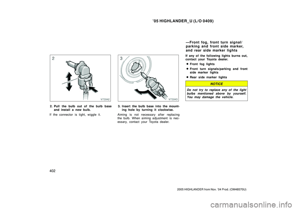
2. Pull the bulb out of the bulb base
and install a new bulb.
If the connector is tight, wiggle it.3. Insert the bulb base into the mount-
ing hole by turning it clockwise.
Aiming is not necessary after replacing
the bulb. When aiming adjustment is nec-
essary, contact your Toyota dealer.If any of the following lights burns out,
contact your Toyota dealer.
�Front fog lights
�Front turn signals/parking and front
side marker lights
�Rear side marker lights
NOTICE
Do not try to replace any of the light
bulbs mentioned above by yourself.
You may damage the vehicle.
ÐFront fog, front turn signal/
parking and front side marker,
and rear side marker lights
Page 1393 of 2572
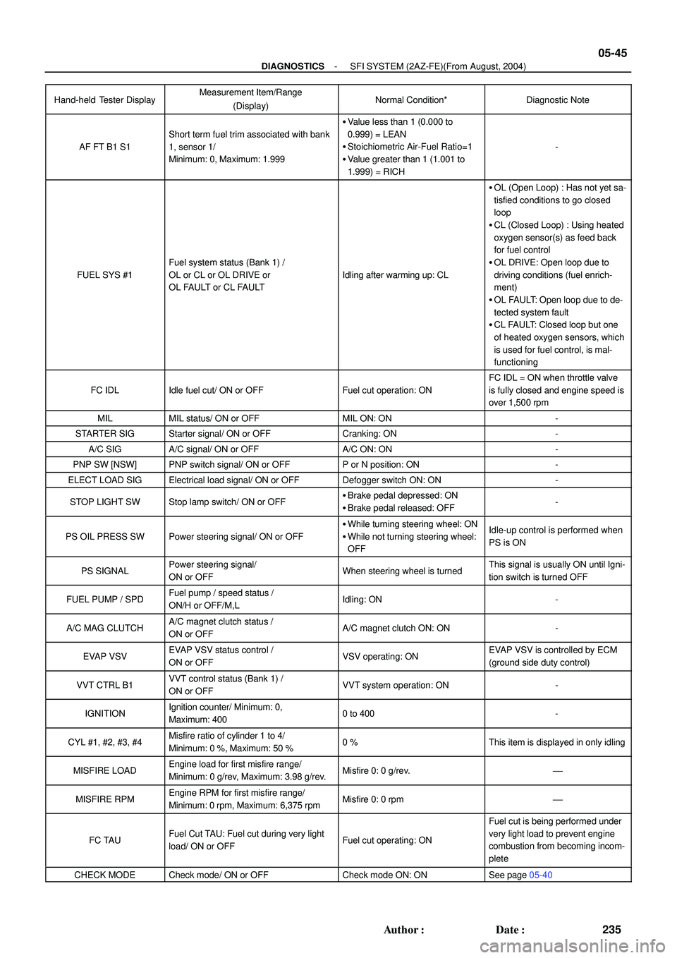
- DIAGNOSTICSSFI SYSTEM (2AZ-FE)(From August, 2004)
05-45
235 Author�: Date�:
Hand-held Tester DisplayDiagnostic Note Normal Condition* Measurement Item/Range
(Display)
AF FT B1 S1
Short term fuel trim associated with bank
1, sensor 1/
Minimum: 0, Maximum: 1.999
�Value less than 1 (0.000 to
0.999) = LEAN
�Stoichiometric Air-Fuel Ratio=1
�Value greater than 1 (1.001 to
1.999) = RICH
-
FUEL SYS #1
Fuel system status (Bank 1) /
OL or CL or OL DRIVE or
OL FAULT or CL FAULT
Idling after warming up: CL
�OL (Open Loop) : Has not yet sa-
tisfied conditions to go closed
loop
�CL (Closed Loop) : Using heated
oxygen sensor(s) as feed back
for fuel control
�OL DRIVE: Open loop due to
driving conditions (fuel enrich-
ment)
�OL FAULT: Open loop due to de-
tected system fault
�CL FAULT: Closed loop but one
of heated oxygen sensors, which
is used for fuel control, is mal-
functioning
FC IDLIdle fuel cut/ ON or OFFFuel cut operation: ON
FC IDL = ON when throttle valve
is fully closed and engine speed is
over 1,500 rpm
MILMIL status/ ON or OFFMIL ON: ON-
STARTER SIGStarter signal/ ON or OFFCranking: ON-
A/C SIGA/C signal/ ON or OFFA/C ON: ON-
PNP SW [NSW]PNP switch signal/ ON or OFFP or N position: ON-
ELECT LOAD SIGElectrical load signal/ ON or OFFDefogger switch ON: ON-
STOP LIGHT SWStop lamp switch/ ON or OFF�Brake pedal depressed: ON
�Brake pedal released: OFF-
PS OIL PRESS SWPower steering signal/ ON or OFF
�While turning steering wheel: ON
�While not turning steering wheel:
OFFIdle-up control is performed when
PS is ON
PS SIGNALPower steering signal/
ON or OFFWhen steering wheel is turnedThis signal is usually ON until Igni-
tion switch is turned OFF
FUEL PUMP / SPDFuel pump / speed status /
ON/H or OFF/M,LIdling: ON-
A/C MAG CLUTCHA/C magnet clutch status /
ON or OFFA/C magnet clutch ON: ON-
EVAP VSVEVAP VSV status control /
ON or OFFVSV operating: ONEVAP VSV is controlled by ECM
(ground side duty control)
VVT CTRL B1VVT control status (Bank 1) /
ON or OFFVVT system operation: ON-
IGNITIONIgnition counter/ Minimum: 0,
Maximum: 4000 to 400-
CYL #1, #2, #3, #4Misfire ratio of cylinder 1 to 4/
Minimum: 0 %, Maximum: 50 %0 %This item is displayed in only idling
MISFIRE LOADEngine load for first misfire range/
Minimum: 0 g/rev, Maximum: 3.98 g/rev.Misfire 0: 0 g/rev.'
MISFIRE RPMEngine RPM for first misfire range/
Minimum: 0 rpm, Maximum: 6,375 rpmMisfire 0: 0 rpm'
FC TAUFuel Cut TAU: Fuel cut during very light
load/ ON or OFFFuel cut operating: ON
Fuel cut is being performed under
very light load to prevent engine
combustion from becoming incom-
plete
CHECK MODECheck mode/ ON or OFFCheck mode ON: ONSee page 05-40
Page 1399 of 2572
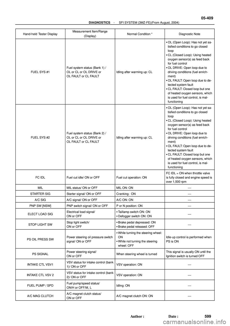
- DIAGNOSTICSSFI SYSTEM (3MZ-FE)(From August, 2004)
05-409
599 Author�: Date�:
Hand-held Tester DisplayDiagnostic Note Normal Condition * Measurement Item/Range
(Display)
FUEL SYS #1
Fuel system status (Bank 1) /
OL or CL or OL DRIVE or
OL FAULT or CL FAULT
Idling after warming up: CL
�OL (Open Loop): Has not yet sa-
tisfied conditions to go closed
loop
�CL (Closed Loop): Using heated
oxygen sensor(s) as feed back
for fuel control
�OL DRIVE: Open loop due to
driving conditions (fuel enrich-
ment)
�OL FAULT: Open loop due to de-
tected system fault
�CL FAULT: Closed loop but one
of heated oxygen sensors, which
is used for fuel control, is mal-
functioning
FUEL SYS #2
Fuel system status (Bank 2) /
OL or CL or OL DRIVE or
OL FAULT or CL FAULT
Idling after warming up: CL
�OL (Open Loop): Has not yet sa-
tisfied conditions to go closed
loop
�CL (Closed Loop): Using heated
oxygen sensor(s) as feed back
for fuel control
�OL DRIVE: Open loop due to
driving conditions (fuel enrich-
ment)
�OL FAULT: Open loop due to de-
tected system fault
�CL FAULT: Closed loop but one
of heated oxygen sensors, which
is used for fuel control, is mal-
functioning
FC IDLFuel cut idle/ ON or OFFFuel cut operation: ON
FC IDL = ON when throttle valve
is fully closed and engine speed is
over 1,500 rpm
MILMIL status/ ON or OFFMIL ON: ON'
STARTER SIGStarter signal/ ON or OFFCranking: ON'
A/C SIGA/C signal/ ON or OFFA/C ON: ON'
PNP SW [NSW]PNP switch signal/ ON or OFFP or N position: ON'
ELECT LOAD SIGElectrical load signal/
ON or OFF�Taillamp switch ON: ON
�Defogger switch ON: ON'
STOP LIGHT SWStop light switch/
ON or OFF�Brake pedal depressed: ON
�Brake pedal released: OFF'
PS OIL PRESS SWPower steering oil pressure switch
signal/ ON or OFF
�While turning the steering wheel:
ON
�While not turning the steering
wheel: OFF
Idle-up control is performed when
PS is ON
PS SIGNALPower steering signal/
ON or OFFWhen steering wheel is turnedThis signal is usually ON until the
Ignition switch is turned OFF
INTAKE CTL VSV1VSV status for intake control (bank
1)/ ON or OFFVSV operation: ON'
INTAKE CTL VSV 2VSV status for intake control (bank
2)/ ON or OFFVSV operation: ON'
FUEL PUMP / SPDFuel pump/speed status/
ON/H or OFF/M, LIdling: ON'
A/C MAG CLUTCHA/C magnet clutch status/
ON or OFFA/C magnet clutch ON: ON'
Page 1528 of 2572
E74080
Body ECU
Passenger Side J/B
C13
Combination Switch
Fog
Light SW
Light
Control SW
Dimmer SWFFOG
HU
HF
TAIL
HEAD
A
OFF
ON
OFF
TAIL
HEAD
AUTO
LOW
HIGH
FLASHBR
Y
O
V
LG
P 6
4F 2
4N Y
11
7
81413 12
1017
L16B10
W-B10
14
B10
15
B10
18
B10
17
B10
16
B10
IA
LFG BFG HU HL HF T H EL A
05-1586
- DIAGNOSTICSLIGHTING SYSTEM
1776 Author�: Date�:
2005 HIGHLANDER REPAIR MANUAL (RM1144U)
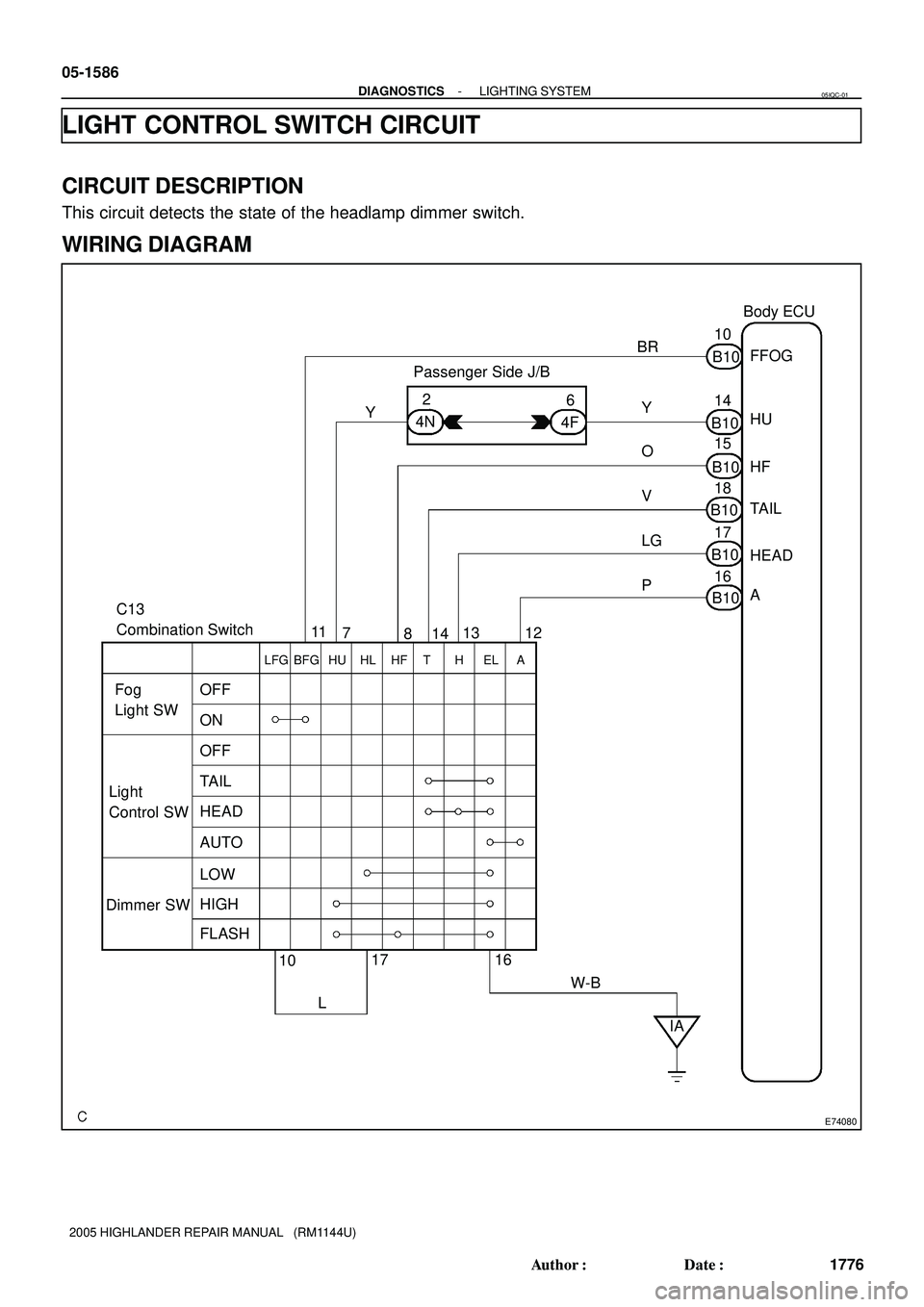
LIGHT CONTROL SWITCH CIRCUIT
CIRCUIT DESCRIPTION
This circuit detects the state of the headlamp dimmer switch.
WIRING DIAGRAM
05IQC-01
Page 1529 of 2572
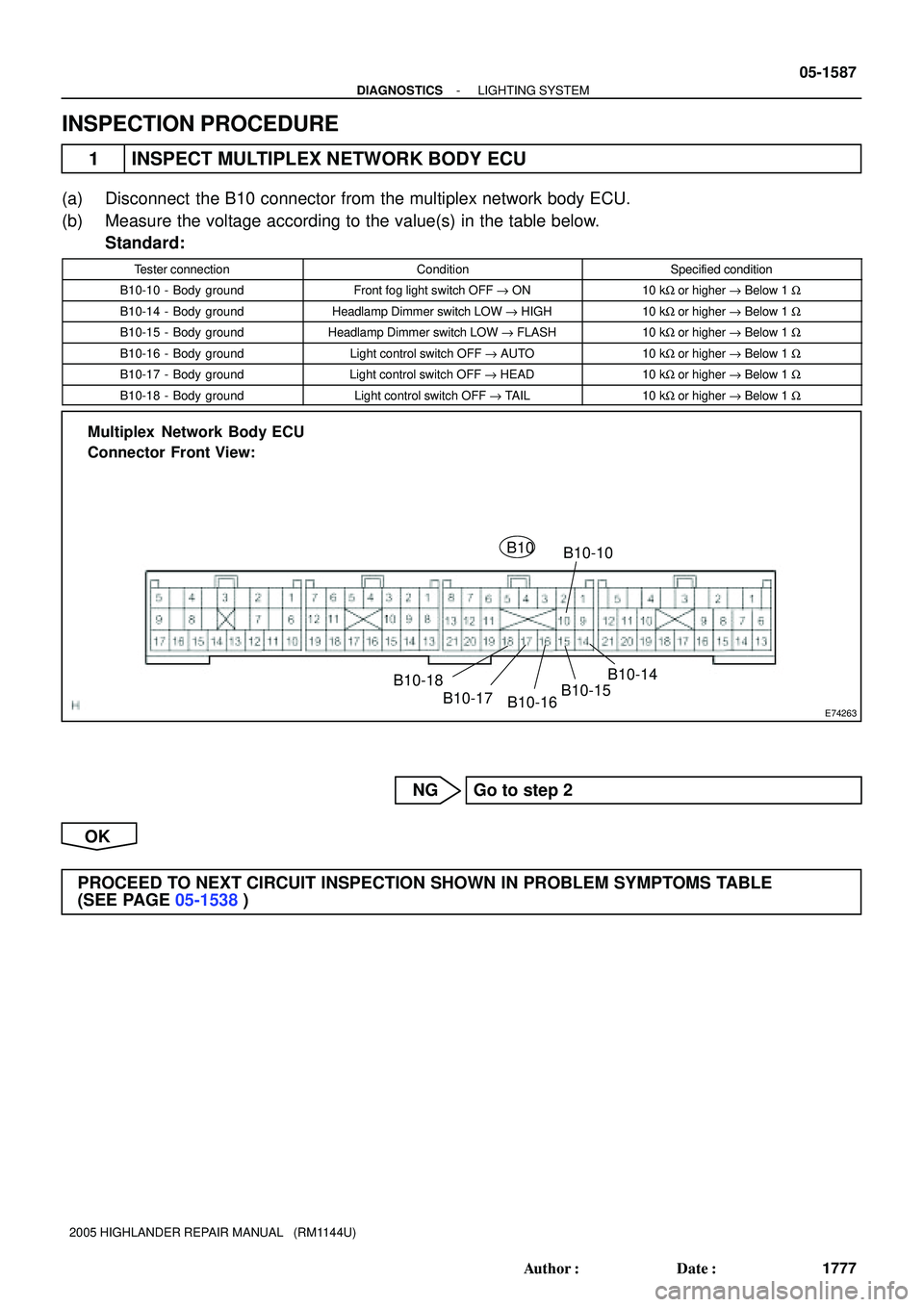
E74263
Multiplex Network Body ECU
Connector Front View:
B10
B10-10
B10-14
B10-15
B10-16 B10-17 B10-18
- DIAGNOSTICSLIGHTING SYSTEM
05-1587
1777 Author�: Date�:
2005 HIGHLANDER REPAIR MANUAL (RM1144U)
INSPECTION PROCEDURE
1 INSPECT MULTIPLEX NETWORK BODY ECU
(a) Disconnect the B10 connector from the multiplex network body ECU.
(b) Measure the voltage according to the value(s) in the table below.
Standard:
Tester connectionConditionSpecified condition
B10-10 - Body groundFront fog light switch OFF " ON10 kW or higher " Below 1 W
B10-14 - Body groundHeadlamp Dimmer switch LOW " HIGH10 kW or higher " Below 1 W
B10-15 - Body groundHeadlamp Dimmer switch LOW " FLASH10 kW or higher " Below 1 W
B10-16 - Body groundLight control switch OFF " AUTO10 kW or higher " Below 1 W
B10-17 - Body groundLight control switch OFF " HEAD10 kW or higher " Below 1 W
B10-18 - Body groundLight control switch OFF " TAIL10 kW or higher " Below 1 W
NG Go to step 2
OK
PROCEED TO NEXT CIRCUIT INSPECTION SHOWN IN PROBLEM SYMPTOMS TABLE
(SEE PAGE 05-1538)
Page 1530 of 2572
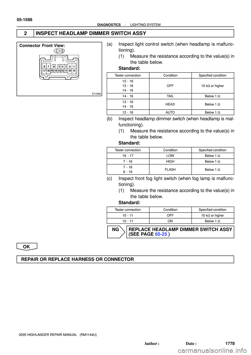
E11948
Connector Front View:
C13
05-1588
- DIAGNOSTICSLIGHTING SYSTEM
1778 Author�: Date�:
2005 HIGHLANDER REPAIR MANUAL (RM1144U)
2 INSPECT HEADLAMP DIMMER SWITCH ASSY
(a) Inspect light control switch (when headlamp is malfunc-
tioning).
(1) Measure the resistance according to the value(s) in
the table below.
Standard:
Tester connectionConditionSpecified condition
12 - 16
13 - 16
14 - 16
OFF10 kW or higher
14 - 16TAILBelow 1 W
13 - 16
14 - 16HEADBelow 1 W
12 - 16AUTOBelow 1 W
(b) Inspect headlamp dimmer switch (when headlamp is mal-
functioning).
(1) Measure the resistance according to the value(s) in
the table below.
Standard:
Tester connectionConditionSpecified condition
16 - 17LOWBelow 1 W
7 - 16HIGHBelow 1 W
7 - 16
8 - 16FLASHBelow 1 W
(c) Inspect front fog light switch (when fog lamp is malfunc-
tioning).
(1) Measure the resistance according to the value(s) in
the table below.
Standard:
Tester connectionConditionSpecified condition
10 - 11OFF10 kW or higher
10 - 11ONBelow 1 W
NG REPLACE HEADLAMP DIMMER SWITCH ASSY
(SEE PAGE 65-25)
OK
REPAIR OR REPLACE HARNESS OR CONNECTOR
Page 1537 of 2572
E74079
Instrument Panel J/B
Body ECU
TAILLIGHT Relay
FOG LIGHT Relay
F2
Front Fog Lamp RH
F1
Front Fog Lamp LH
F7
FL BlockTRLY
FFGO TAIL
FR FOG
W-B
R-W R-W R-W
FL MAIN
BatteryALT4
12
53 1
1A BSB
V7
B9
6
B9
W
2
1
EG EA 12
122
1J
7
1B
W-B1J
A
A
J1
J/CJ3
J/C 12
35 05-1582
- DIAGNOSTICSLIGHTING SYSTEM
1772 Author�: Date�:
2005 HIGHLANDER REPAIR MANUAL (RM1144U)
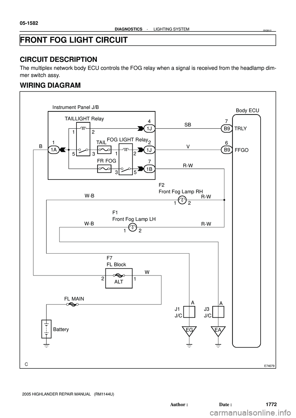
FRONT FOG LIGHT CIRCUIT
CIRCUIT DESCRIPTION
The multiplex network body ECU controls the FOG relay when a signal is received from the headlamp dim-
mer switch assy.
WIRING DIAGRAM
05IQB-01
Page 1538 of 2572
E74263
Multiplex Network Body ECU
Connector Front View:
B9
B9-7
B9-6
- DIAGNOSTICSLIGHTING SYSTEM
05-1583
1773 Author�: Date�:
2005 HIGHLANDER REPAIR MANUAL (RM1144U)
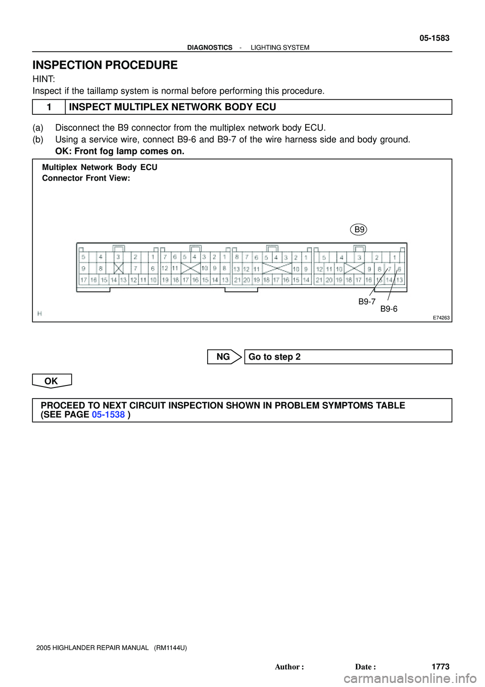
INSPECTION PROCEDURE
HINT:
Inspect if the taillamp system is normal before performing this procedure.
1 INSPECT MULTIPLEX NETWORK BODY ECU
(a) Disconnect the B9 connector from the multiplex network body ECU.
(b) Using a service wire, connect B9-6 and B9-7 of the wire harness side and body ground.
OK: Front fog lamp comes on.
NG Go to step 2
OK
PROCEED TO NEXT CIRCUIT INSPECTION SHOWN IN PROBLEM SYMPTOMS TABLE
(SEE PAGE 05-1538)