Page 1432 of 2572

05-334
- DIAGNOSTICSSFI SYSTEM (2AZ-FE)
524 Author�: Date�:
2005 HIGHLANDER REPAIR MANUAL (RM1144U)
12 PERFORM ACTIVE TEST(PURGE VSV)
(a) On the hand-held tester,")
A85254
Purge VSV
Hose (to canister)
05-334
- DIAGNOSTICSSFI SYSTEM (2AZ-FE)
524 Author�: Date�:
2005 HIGHLANDER REPAIR MANUAL (RM1144U)
12 PERFORM ACTIVE TEST(PURGE VSV)
(a) On the hand-held tester, select the following menu items:
DIAGNOSIS / ENHANCED OBD II/ ACTIVE TEST /
EVAP VSV.
(b) Disconnect the hose (connected to the canister) from the
purge VSV.
(c) Start the engine.
(d) On the tester, turn off the purge VSV (EVAP VSV: OFF).
(e) Use your finger to confirm that the purge VSV has no suc-
tion.
(f) Using the tester, turn on the purge VSV (EVAP VSV: ON).
(g) Use your finger to confirm that the purge VSV has suction.
Result:
Test ResultsSuspected Trouble AreasProceed To
No suction when purge VSV turned OFF, and suction applied
when tuned ONPurge VSV normalA
Suction applied when purge VSV turned OFFPurge VSV stuck openB
No suction when purge VSV turned ON
�Purge VSV stuck closed
�Problems with EVAP hose between purge VSV and throttle
body
C
(h) Reconnect the hose.
B Go to step 14
C Go to step 15
A
Page 1436 of 2572

A85259
ECM
E5
27 (VPMP)
05-338
- DIAGNOSTICSSFI SYSTEM (2AZ-FE)
528 Author�: Date�:
2005 HIGHLANDER REPAIR MANUAL (RM1144U)
19 PERFORM ACTIVE TEST USING HAND-HELD TESTER(FOR")
A85259
ECM
E5
27 (VPMP)
A85259
ECM
E5
27 (VPMP)
05-338
- DIAGNOSTICSSFI SYSTEM (2AZ-FE)
528 Author�: Date�:
2005 HIGHLANDER REPAIR MANUAL (RM1144U)
19 PERFORM ACTIVE TEST USING HAND-HELD TESTER(FOR VENT VALVE)
(a) Turn the ignition switch to ON.
(b) On the hand-held tester, select the following menu items:
DIAGNOSIS/ ENHANCED OBD II/ ACTIVE TEST/ VENT
VALVE (ALONE).
(c) Measure the voltage between terminal VPMP of the ECM
connector and the body ground when the vent valve is
turned ON (close) and OFF (vent) using the tester.
Result:
Test ResultsSuspected Trouble AreasProceed To
Between 9 V and 14 V when OFF
Below 3 V when ONVent valveA
Below 3 V when OFF and ONECMB
A Go to step 22
B Go to step 35
20 PERFORM ACTIVE TEST USING HAND-HELD TESTER(FOR VENT VALVE)
(a) Turn the ignition switch to ON.
(b) On the hand-held tester, select the following menu items:
DIAGNOSIS/ ENHANCED OBD II/ ACTIVE TEST/ VENT
VALVE (ALONE).
(c) Measure the voltage between terminal VPMP of the ECM
connector and the body ground when the vent valve is
turned ON (close) and OFF (vent) using the tester.
Result:
Test ResultsSuspected Trouble AreasProceed To
Below 3 V when OFF and ONPower source of vent valveA
Between 9 V and 14 V when OFF
Below 3 V when ONVent valveB
Between 9 V and 14 V when OFF and ONECMC
B Go to step 22
C Go to step 35
A
Page 1438 of 2572
 9 (+)
A85259
ECM
E5
4 (MPMP)
05-340
- DIAGNOSTICSSFI SYSTEM (2AZ-FE)
530 Author�: Date�:
2005 HIGHLANDER REPAIR MANUAL (RM1144U)
22 INSPECT PUMP MODULE(VENT VALVE OPERATION)
(a) Turn th")
A85253
8 (-) 9 (+)
A85259
ECM
E5
4 (MPMP)
05-340
- DIAGNOSTICSSFI SYSTEM (2AZ-FE)
530 Author�: Date�:
2005 HIGHLANDER REPAIR MANUAL (RM1144U)
22 INSPECT PUMP MODULE(VENT VALVE OPERATION)
(a) Turn the ignition switch to OFF.
(b) Disconnect the canister connector.
(c) Apply the battery voltage to terminals 9 and 8 of the pump
module.
(d) Touch the pump module to confirm the vent valve opera-
tion.
Result:
Test ResultsSuspected Trouble AreasProceed To
OperatingWire harness between vent valve and ECMA
Not operatingVent valveB
(e) Reconnect the canister connector.
A Go to step 32
B Go to step 30
23 PERFORM ACTIVE TEST USING HAND-HELD TESTER(FOR PUMP
MODULE(VACUUM PUMP)
(a) On the hand-held tester, select the following menu items:
DIAGNOSIS / ENHANCED OBD II / ACTIVE TEST / VAC-
UUM PUMP (ALONE).
(b) Measure the voltage between terminal MPMP of the ECM
connector and the body ground when the vacuum pump
is turned ON and OFF using the tester.
Result:
Tests ResultsSuspected Trouble AreasProceed To
Between 0 V and 3 V when OFF
Between 9 V and 14 V when ONECM normalA
Between 9 V and 14 V when OFF
Between 0 V and 3 V when ONECMB
B Go to step 35
A
Page 1439 of 2572
A85252
C17
A85258
Wire Harness Side
C17
Canister
- DIAGNOSTICSSFI SYSTEM (2AZ-FE)
05-341
531 Author�: Date�:
2005 HIGHLANDER REPAIR MANUAL (RM1144U)
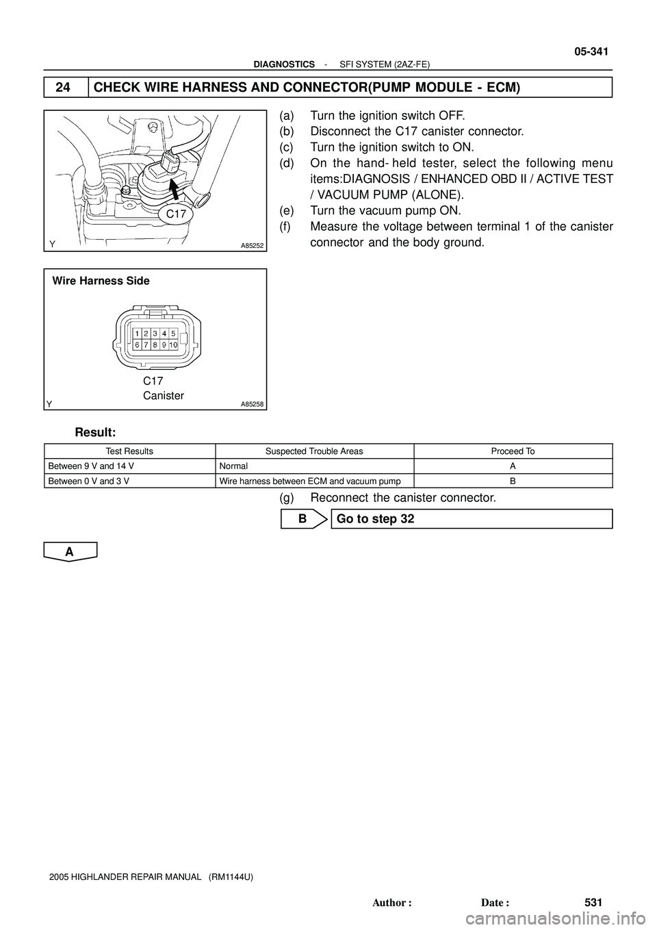
24 CHECK WIRE HARNESS AND CONNECTOR(PUMP MODULE - ECM)
(a) Turn the ignition switch OFF.
(b) Disconnect the C17 canister connector.
(c) Turn the ignition switch to ON.
(d) On the hand- held tester, select the following menu
items:DIAGNOSIS / ENHANCED OBD II / ACTIVE TEST
/ VACUUM PUMP (ALONE).
(e) Turn the vacuum pump ON.
(f) Measure the voltage between terminal 1 of the canister
connector and the body ground.
Result:
Test ResultsSuspected Trouble AreasProceed To
Between 9 V and 14 VNormalA
Between 0 V and 3 VWire harness between ECM and vacuum pumpB
(g) Reconnect the canister connector.
B Go to step 32
A
Page 1443 of 2572

05-345
535 Author�: Date�:
2005 HIGHLANDER REPAIR MANUAL (RM1144U)
37 PERFORM EVAP SYSTEM CHECK(AUTO OPERATION)
NOTICE:
�In the EVAP SYSTEM CHECK (AUTO OPERATION), t")
- DIAGNOSTICSSFI SYSTEM (2AZ-FE)
05-345
535 Author�: Date�:
2005 HIGHLANDER REPAIR MANUAL (RM1144U)
37 PERFORM EVAP SYSTEM CHECK(AUTO OPERATION)
NOTICE:
�In the EVAP SYSTEM CHECK (AUTO OPERATION), the series of 5 EVAP SYSTEM CHECK steps
is performed automatically. It takes a maximum of approximately 18 minutes.
�Do not perform the EVAP SYSTEM CHECK when the fuel tank is more than 90% full because
the cut-off valve may be closed, making the leak check of the fuel tank unavailable.
�Do not run the engine in this step.
�When the temperature of the fuel is 35�C (95�F) or more, a large amount of vapor forms and any
check results become inaccurate. When performing an EVAP SYSTEM CHECK, keep the tem-
perature below 35�C
(95�F).
(a) Clear DTCs (see page 05-38).
(b) On the hand-held tester, select the following menu items: DIAGNOSIS / ENHANCED OBD II / SYS-
TEM CHECK / EVAP SYS CHECK / AUTO OPERATION.
(c) After the SYSTEM CHECK is completed, check for pending DTCs by selecting the following menu
items: DIAGNOSIS / ENHANCED OBD II / DTC INFO / PENDING CODES.
HINT:
If no pending DTC is found, the repair has been successfully completed.
NEXT
COMPLETED
Page 1444 of 2572

536 Author�: Date�:
2005 HIGHLANDER REPAIR MANUAL (RM1144U)
Monitor Confirmation
HINT:
After a repair, check Monitor Status by performing the Key-Off Monitor")
05-346
- DIAGNOSTICSSFI SYSTEM (2AZ-FE)
536 Author�: Date�:
2005 HIGHLANDER REPAIR MANUAL (RM1144U)
Monitor Confirmation
HINT:
After a repair, check Monitor Status by performing the Key-Off Monitor Confirmation and Purge Flow Monitor
Confirmation described below.
1. KEY-OFF MONITOR CONFIRMATION
(a) Preconditions
The monitor will not run unless:
�The vehicle has been driven for 10 minutes or more (in a city area or on a free way)
�The fuel tank is less than 90% full
�The altitude is less than 8,000 ft (2,400 m)
�The Engine Coolant Temperature (ECT) is between 4.4�C and 35�C (40�F and 95�F)
�The Intake Air Temperature (IAT) is between 4.4�C and 35�C (40�F and 95�F)
�The vehicle remains stationary (the vehicle speed is 0 mph [0 km/h])
(b) Monitor Conditions
(1) Allow the engine to idle for at least 5 minutes.
(2) Turn the ignition switch OFF and wait for 6 hours (8 or 10.5 hours).
HINT:
Do not start the engine until checking MONITOR STATUS. If the engine is started, the steps described above
must be repeated.
(c) Monitor Status
(1) Connect a hand-held tester to the DLC3.
(2) Turn the ignition switch ON and turn the tester ON.
(3) On the tester, select the following menu items: DIAGNOSIS / ENHANCED OBD II / MONITOR
STATUS.
(4) Check the Monitor Status displayed on the tester.
HINT:
If INCMP is displayed, the monitor is not completed. Make sure that the preconditions have been met, and
perform the Monitor Conditions again.
2. PURGE FLOW MONITOR CONFIRMATION (P0441)
HINT:
Perform this monitor confirmation after the Key-Off Monitor Confirmation shows COMPL (complete).
(a) Preconditions
The monitor will not run unless:
�The vehicle has been driven for 10 minutes or more (in a city area or on a free way)
�The ECT is between 4.4�C and 35�C (40�F and 95�F)
�The IAT is between 4.4�C and 35�C (40�F and 95�F)
(b) Monitor Conditions
(1) Release the pressure from the fuel tank by removing and reinstalling the fuel tank cap.
(2) Warm the engine up until the ECT reaches more than 75�C (167�F).
(3) Increase the engine speed to 3,000 rpm once.
(4) Allow the engine to idle and turn A/C ON for 1 minute.
(c) Monitor Status
(1) Turn the ignition switch OFF (where ON or the engine is running).
(2) Connect a hand-held tester to the DLC3.
(3) Turn the ignition switch to ON and turn the tester ON.
(4) On the tester, select the following menu items: DIAGNOSIS / ENHANCED OBD II / MONITOR
STATUS.
(5) Check the Monitor Status displayed on the tester.
Page 1450 of 2572
E1 (-)
E9
ECME5
ECM
- DIAGNOSTICSSFI SYSTEM (2AZ-FE)
05-351
541 Author�: Date�:
2005 HIGHLANDER REPAIR MANUAL (RM1144U)
INSPECTION PROCEDURE
Hand-held tester:
1 PERF")
B60778
5
12 312
5
3
A67446
FC (+)E1 (-)
E9
ECME5
ECM
- DIAGNOSTICSSFI SYSTEM (2AZ-FE)
05-351
541 Author�: Date�:
2005 HIGHLANDER REPAIR MANUAL (RM1144U)
INSPECTION PROCEDURE
Hand-held tester:
1 PERFORM ACTIVE TEST USING HAND-HELD TESTER (OPERATE CIRCUIT
OPENING RELAY)
(a) Connect the hand-held tester to the DLC3.
(b) Turn ON the ignition switch. Push the hand-held tester main switch.
(c) Enter the following menus: DIAGNOSIS / ENHANCED OBD II / ACTIVE TEST / FUEL PUMP / SPD.
(d) Check the relay operation while operating it with the hand-held tester.
OK: Operating noise can be heard from the relay.
OK Go to step 5
NG
2 INSPECT CIRCUIT OPENING RELAY
(a) Remove the circuit opening relay from the R/B sub-assy.
(b) Measure the resistance of the circuit opening relay.
Standard:
Tester ConnectionSpecified Condition
3 - 510 kW or higher
3 - 5Below 1 W
(when battery voltage is applied to terminals 1 and 2)
NG REPLACE CIRCUIT OPENING RELAY
OK
3 INSPECT ECM (FC VOLTAGE)
(a) Turn the ignition switch ON.
(b) Measure the voltage of the ECM connectors.
Standard:
Tester ConnectionSpecified Condition
E5-10 (FC) - E9-1 (E1)9 to 14 V
OK REPLACE ECM (See page 10-9)
NG
Page 1603 of 2572
05IS3-02
I38224
I38225
I38226
05-1764
- DIAGNOSTICSNAVIGATION SYSTEM
1954 Author�: Date�:
2005 HIGHLANDER REPAIR MANUAL (RM1144U)
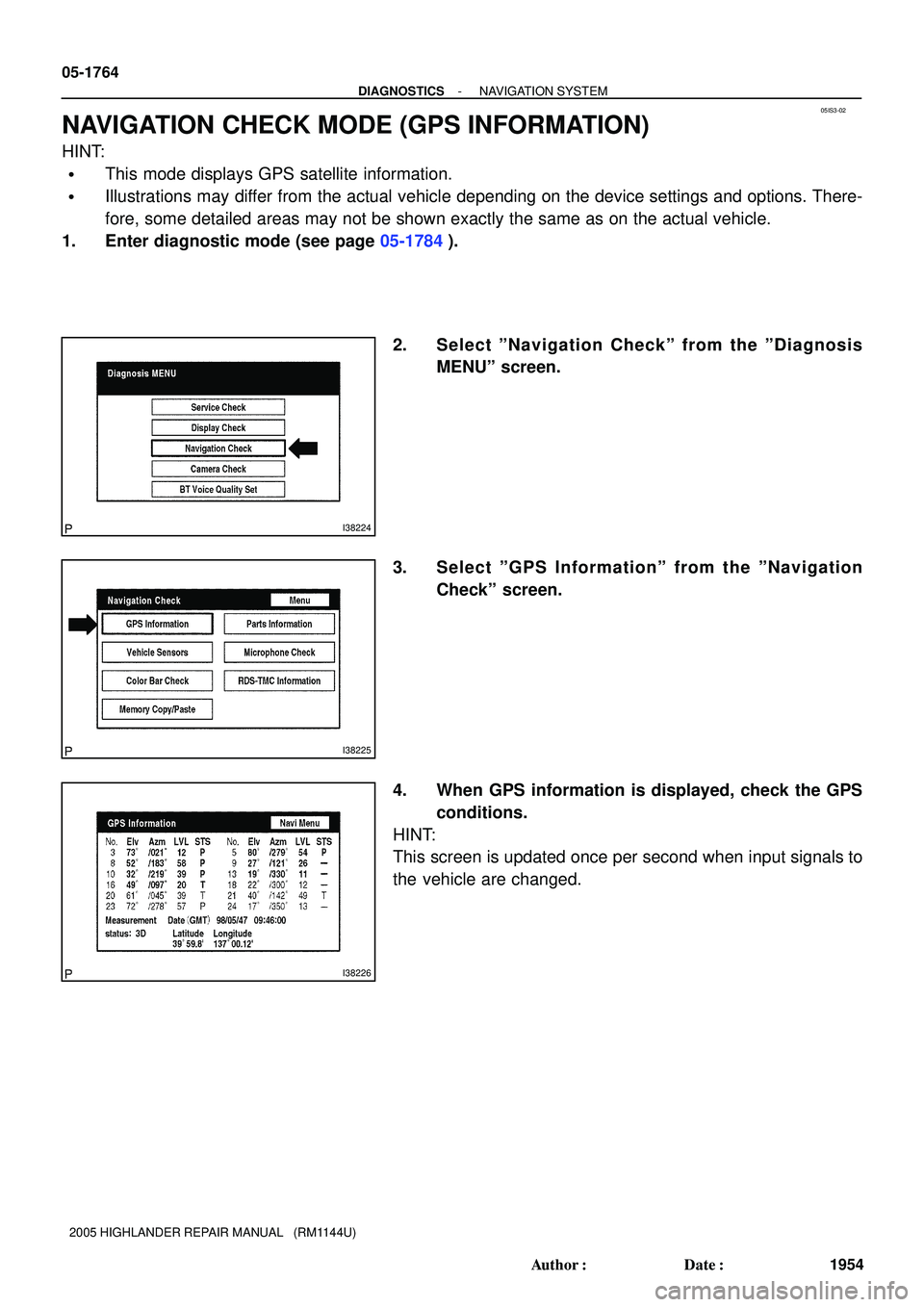
NAVIGATION CHECK MODE (GPS INFORMATION)
HINT:
�This mode displays GPS satellite information.
�Illustrations may differ from the actual vehicle depending on the device settings and options. There-
fore, some detailed areas may not be shown exactly the same as on the actual vehicle.
1. Enter diagnostic mode (see page 05-1784).
2. Select ºNavigation Checkº from the ºDiagnosis
MENUº screen.
3. Select ºGPS Informationº from the ºNavigation
Checkº screen.
4. When GPS information is displayed, check the GPS
conditions.
HINT:
This screen is updated once per second when input signals to
the vehicle are changed.