Page 1374 of 2572
05IRZ-02
I38215
I38216
I38217
05-1760
- DIAGNOSTICSNAVIGATION SYSTEM
1950 Author�: Date�:
2005 HIGHLANDER REPAIR MANUAL (RM1144U)
DISPLAY CHECK MODE (COLOR BAR CHECK)
HINT:
�This mode checks the color display on the multi-display.
�Illustrations may differ from the actual vehicle depending on the device settings and options. There-
fore, some detailed areas may not be shown exactly the same as on the actual vehicle.
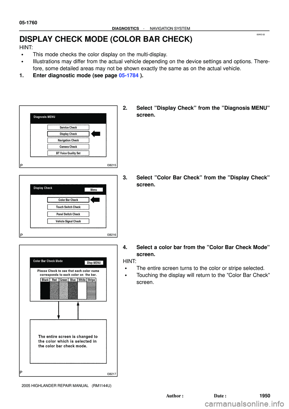
1. Enter diagnostic mode (see page 05-1784).
2. Select ºDisplay Checkº from the ºDiagnosis MENUº
screen.
3. Select ºColor Bar Checkº from the ºDisplay Checkº
screen.
4. Select a color bar from the ºColor Bar Check Modeº
screen.
HINT:
�The entire screen turns to the color or stripe selected.
�Touching the display will return to the ºColor Bar Checkº
screen.
Page 1375 of 2572
05IS1-02
I38215
I38220
I38221
*1
*2 *3
05-1762
- DIAGNOSTICSNAVIGATION SYSTEM
1952 Author�: Date�:
2005 HIGHLANDER REPAIR MANUAL (RM1144U)
DISPLAY CHECK MODE (PANEL SWITCH CHECK)
HINT:
�This mode checks the panel switch operation response on the multi-display.
�Illustrations may differ from the actual vehicle depending on the device settings and options. There-
fore, some detailed areas may not be shown exactly the same as on the actual vehicle.
1. Enter diagnostic mode (see page 05-1784).
2. Select ºDisplay Checkº from the ºDiagnosis Menuº
screen.
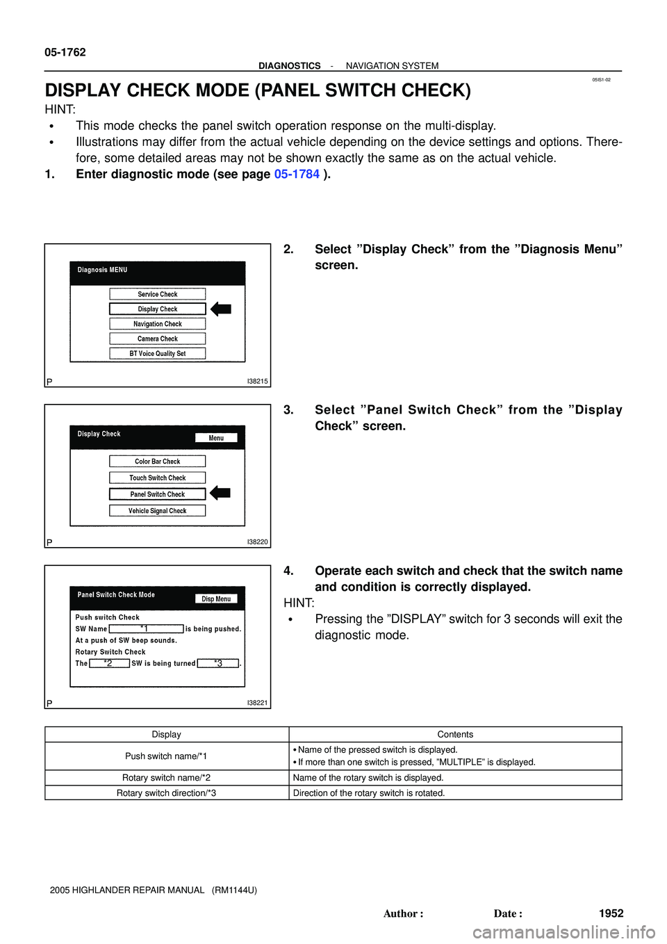
3. Select ºPanel Switch Checkº from the ºDisplay
Checkº screen.
4. Operate each switch and check that the switch name
and condition is correctly displayed.
HINT:
�Pressing the ºDISPLAYº switch for 3 seconds will exit the
diagnostic mode.
DisplayContents
Push switch name/*1�Name of the pressed switch is displayed.
�If more than one switch is pressed, ºMULTIPLEº is displayed.
Rotary switch name/*2Name of the rotary switch is displayed.
Rotary switch direction/*3Direction of the rotary switch is rotated.
Page 1376 of 2572
05IS0-02
I38215
I38218
I38219
- DIAGNOSTICSNAVIGATION SYSTEM
05-1761
1951 Author�: Date�:
2005 HIGHLANDER REPAIR MANUAL (RM1144U)
DISPLAY CHECK MODE (TOUCH SWITCH CHECK)
HINT:
�This mode checks the touch switch operation condition on the multi-display.
�Illustrations may differ from the actual vehicle depending on the device settings and options. There-
fore, some detailed areas may not be shown exactly the same as on the actual vehicle.
1. Enter diagnostic mode (see page 05-1784).
2. Select ºDisplay Checkº from the ºDiagnosis MENUº
screen.
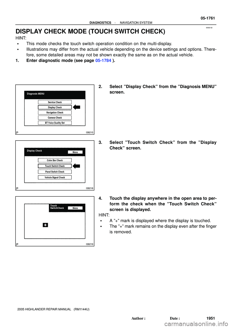
3. Select ºTouch Switch Checkº from the ºDisplay
Checkº screen.
4. Touch the display anywhere in the open area to per-
form the check when the ºTouch Switch Checkº
screen is displayed.
HINT:
�A º+º mark is displayed where the display is touched.
�The º+º mark remains on the display even after the finger
is removed.
Page 1377 of 2572
05IS2-02
I38215
I38222
I38223
- DIAGNOSTICSNAVIGATION SYSTEM
05-1763
1953 Author�: Date�:
2005 HIGHLANDER REPAIR MANUAL (RM1144U)
DISPLAY CHECK MODE (VEHICLE SIGNAL CHECK)
HINT:
�This mode checks the vehicle signal status input to the multi-display.
�Illustrations may differ from the actual vehicle depending on the device settings and options. There-
fore, some detailed areas may not be shown exactly the same as on the actual vehicle.
1. Enter diagnostic mode (see page 05-1784).
2. Select ºDisplay Checkº from the ºDiagnosis MENUº
screen.
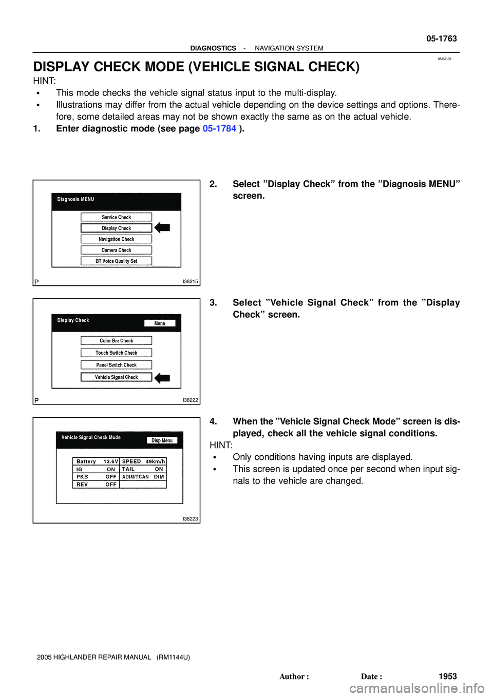
3. Select ºVehicle Signal Checkº from the ºDisplay
Checkº screen.
4. When the ºVehicle Signal Check Modeº screen is dis-
played, check all the vehicle signal conditions.
HINT:
�Only conditions having inputs are displayed.
�This screen is updated once per second when input sig-
nals to the vehicle are changed.
Page 1380 of 2572
I38666
- DIAGNOSTICSNAVIGATION SYSTEM
05-1769
1959 Author�: Date�:
2005 HIGHLANDER REPAIR MANUAL (RM1144U)
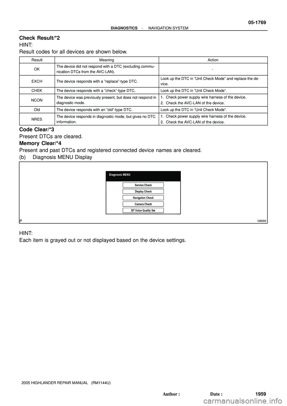
Check Result/*2
HINT:
Result codes for all devices are shown below.
ResultMeaningAction
OKThe device did not respond with a DTC (excluding commu-
nication DTCs from the AVC-LAN).-
EXCHThe device responds with a ºreplaceº-type DTC.Look up the DTC in ºUnit Check Modeº and replace the de-
vice.
CHEKThe device responds with a ºcheckº-type DTC.Look up the DTC in ºUnit Check Modeº.
NCONThe device was previously present, but does not respond in
diagnostic mode.1. Check power supply wire harness of the device.
2. Check the AVC-LAN of the device.
OldThe device responds with an ºoldº-type DTC.Look up the DTC in ºUnit Check Modeº.
NRESThe device responds in diagnostic mode, but gives no DTC
information.1. Check power supply wire harness of the device.
2. Check the AVC-LAN of the device.
Code Clear/*3
Present DTCs are cleared.
Memory Clear/*4
Present and past DTCs and registered connected device names are cleared.
(b) Diagnosis MENU Display
HINT:
Each item is grayed out or not displayed based on the device settings.
Page 1383 of 2572
I38667
I38592
*2
*3*2
*5
*4
*1 *1
05-1772
- DIAGNOSTICSNAVIGATION SYSTEM
1962 Author�: Date�:
2005 HIGHLANDER REPAIR MANUAL (RM1144U)
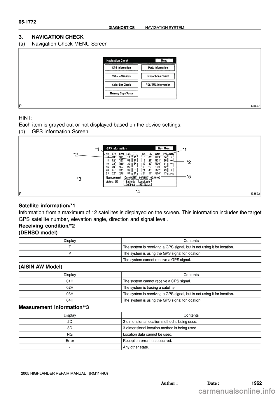
3. NAVIGATION CHECK
(a) Navigation Check MENU Screen
HINT:
Each item is grayed out or not displayed based on the device settings.
(b) GPS information Screen
Satellite information/*1
Information from a maximum of 12 satellites is displayed on the screen. This information includes the target
GPS satellite number, elevation angle, direction and signal level.
Receiving condition/*2
(DENSO model)
DisplayContents
TThe system is receiving a GPS signal, but is not using it for location.
PThe system is using the GPS signal for location.
-The system cannot receive a GPS signal.
(AISIN AW Model)
DisplayContents
01HThe system cannot receive a GPS signal.
02HThe system is tracing a satellite.
03HThe system is receiving a GPS signal, but is not using it for location.
04HThe system is using the GPS signal for location.
Measurement information/*3
DisplayContents
2D2-dimensional location method is being used.
3D3-dimensional location method is being used.
NGLocation data cannot be used.
ErrorReception error has occurred.
-Any other state.
Page 1386 of 2572
05ISA-02
I40190
I38204
I38205
05-1784
- DIAGNOSTICSNAVIGATION SYSTEM
1974 Author�: Date�:
2005 HIGHLANDER REPAIR MANUAL (RM1144U)
DIAGNOSTIC START-UP/FINISH
HINT:
�Illustrations may differ from the actual vehicle depending on the device settings and options. There-
fore, some detailed areas may not be shown exactly the same as on the actual vehicle.
�After the ignition switch is turned on, check that the map is displayed before starting the diagnostic
mode. Otherwise, some items cannot be checked.
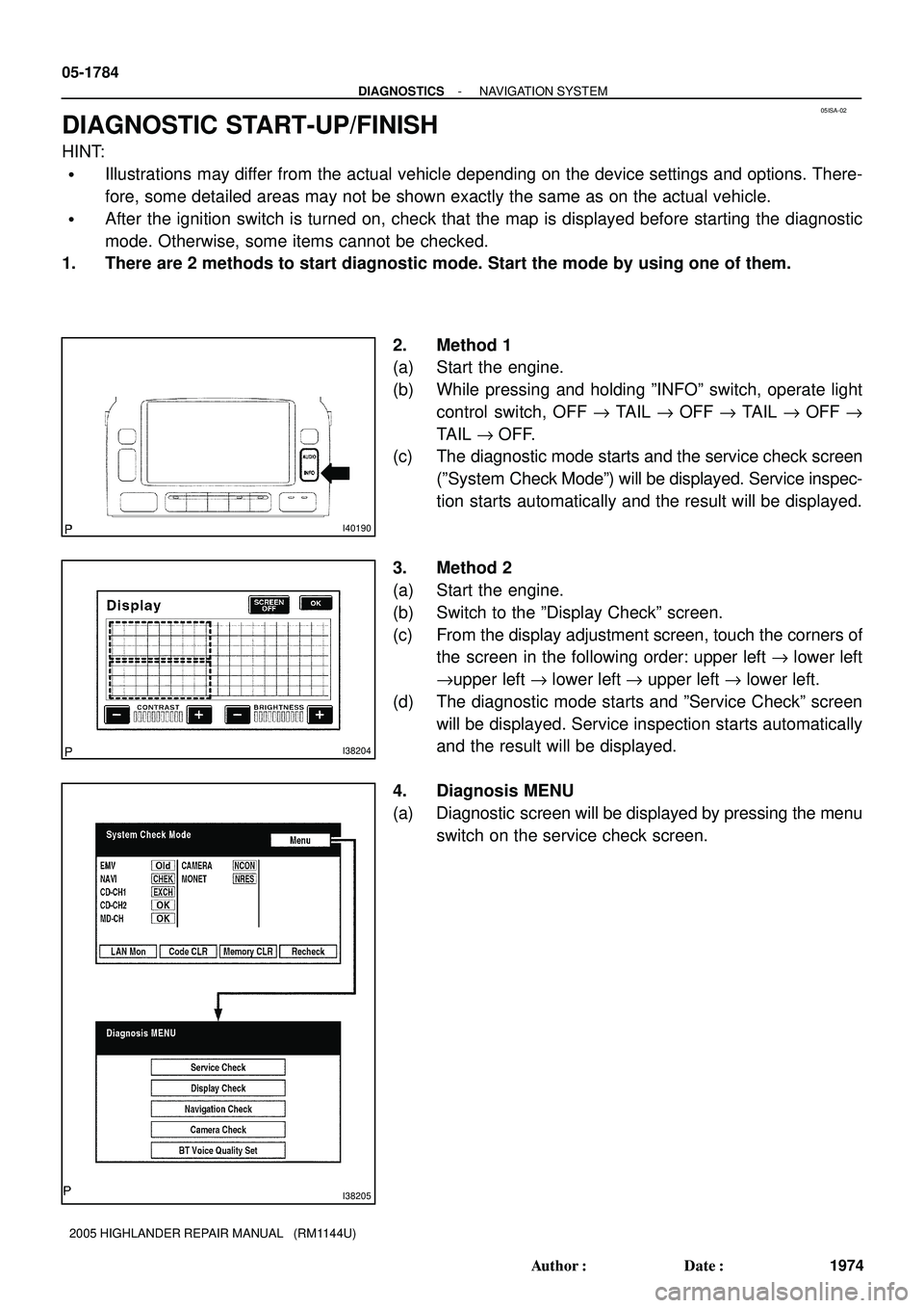
1. There are 2 methods to start diagnostic mode. Start the mode by using one of them.
2. Method 1
(a) Start the engine.
(b) While pressing and holding ºINFOº switch, operate light
control switch, OFF " TAIL " OFF " TAIL " OFF "
TAIL " OFF.
(c) The diagnostic mode starts and the service check screen
(ºSystem Check Modeº) will be displayed. Service inspec-
tion starts automatically and the result will be displayed.
3. Method 2
(a) Start the engine.
(b) Switch to the ºDisplay Checkº screen.
(c) From the display adjustment screen, touch the corners of
the screen in the following order: upper left " lower left
"upper left " lower left " upper left " lower left.
(d) The diagnostic mode starts and ºService Checkº screen
will be displayed. Service inspection starts automatically
and the result will be displayed.
4. Diagnosis MENU
(a) Diagnostic screen will be displayed by pressing the menu
switch on the service check screen.
Page 1391 of 2572
05ESS-05
- DIAGNOSTICSSFI SYSTEM (2AZ-FE)(From August, 2004)
05-43
233 Author�: Date�:
DATA LIST/ACTIIVE TEST/SYSTEM CHECK/SYSTEM CHECK
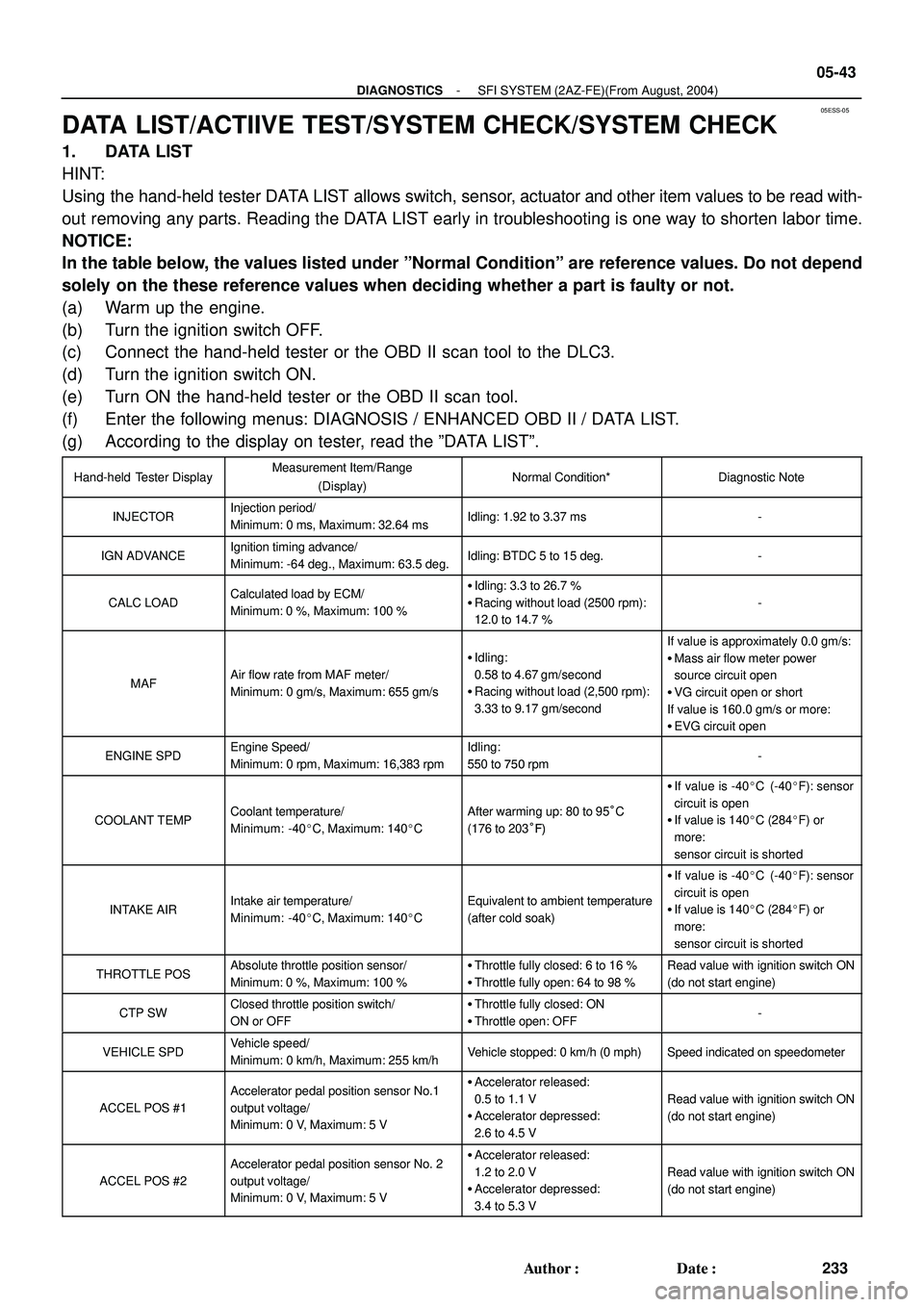
1. DATA LIST
HINT:
Using the hand-held tester DATA LIST allows switch, sensor, actuator and other item values to be read with-
out removing any parts. Reading the DATA LIST early in troubleshooting is one way to shorten labor time.
NOTICE:
In the table below, the values listed under ºNormal Conditionº are reference values. Do not depend
solely on the these reference values when deciding whether a part is faulty or not.
(a) Warm up the engine.
(b) Turn the ignition switch OFF.
(c) Connect the hand-held tester or the OBD II scan tool to the DLC3.
(d) Turn the ignition switch ON.
(e) Turn ON the hand-held tester or the OBD II scan tool.
(f) Enter the following menus: DIAGNOSIS / ENHANCED OBD II / DATA LIST.
(g) According to the display on tester, read the ºDATA LISTº.
Hand-held Tester DisplayMeasurement Item/Range
(Display)Normal Condition*Diagnostic Note
INJECTORInjection period/
Minimum: 0 ms, Maximum: 32.64 msIdling: 1.92 to 3.37 ms-
IGN ADVANCEIgnition timing advance/
Minimum: -64 deg., Maximum: 63.5 deg.Idling: BTDC 5 to 15 deg.-
CALC LOADCalculated load by ECM/
Minimum: 0 %, Maximum: 100 %�Idling: 3.3 to 26.7 %
�Racing without load (2500 rpm):
12.0 to 14.7 %
-
MAFAir flow rate from MAF meter/
Minimum: 0 gm/s, Maximum: 655 gm/s
�Idling:
0.58 to 4.67 gm/second
�Racing without load (2,500 rpm):
3.33 to 9.17 gm/second
If value is approximately 0.0 gm/s:
�Mass air flow meter power
source circuit open
�VG circuit open or short
If value is 160.0 gm/s or more:
�EVG circuit open
ENGINE SPDEngine Speed/
Minimum: 0 rpm, Maximum: 16,383 rpmIdling:
550 to 750 rpm-
COOLANT TEMPCoolant temperature/
Minimum: -40�C, Maximum: 140�CAfter warming up: 80 to 95°C
(176 to 203°F)
�If value is -40�C (-40�F): sensor
circuit is open
�If value is 140�C (284�F) or
more:
sensor circuit is shorted
INTAKE AIRIntake air temperature/
Minimum: -40�C, Maximum: 140�CEquivalent to ambient temperature
(after cold soak)
�If value is -40�C (-40�F): sensor
circuit is open
�If value is 140�C (284�F) or
more:
sensor circuit is shorted
THROTTLE POSAbsolute throttle position sensor/
Minimum: 0 %, Maximum: 100 %�Throttle fully closed: 6 to 16 %
�Throttle fully open: 64 to 98 %Read value with ignition switch ON
(do not start engine)
CTP SWClosed throttle position switch/
ON or OFF�Throttle fully closed: ON
�Throttle open: OFF-
VEHICLE SPDVehicle speed/
Minimum: 0 km/h, Maximum: 255 km/hVehicle stopped: 0 km/h (0 mph)Speed indicated on speedometer
ACCEL POS #1
Accelerator pedal position sensor No.1
output voltage/
Minimum: 0 V, Maximum: 5 V�Accelerator released:
0.5 to 1.1 V
�Accelerator depressed:
2.6 to 4.5 V
Read value with ignition switch ON
(do not start engine)
ACCEL POS #2
Accelerator pedal position sensor No. 2
output voltage/
Minimum: 0 V, Maximum: 5 V�Accelerator released:
1.2 to 2.0 V
�Accelerator depressed:
3.4 to 5.3 V
Read value with ignition switch ON
(do not start engine)